EP0401583A1 - Verfahren und Einrichtung zum Absaugen von Dämpfen und Dunststoffen - Google Patents
Verfahren und Einrichtung zum Absaugen von Dämpfen und Dunststoffen Download PDFInfo
- Publication number
- EP0401583A1 EP0401583A1 EP90109564A EP90109564A EP0401583A1 EP 0401583 A1 EP0401583 A1 EP 0401583A1 EP 90109564 A EP90109564 A EP 90109564A EP 90109564 A EP90109564 A EP 90109564A EP 0401583 A1 EP0401583 A1 EP 0401583A1
- Authority
- EP
- European Patent Office
- Prior art keywords
- hood
- flow
- filter
- jet
- wall jet
- Prior art date
- Legal status (The legal status is an assumption and is not a legal conclusion. Google has not performed a legal analysis and makes no representation as to the accuracy of the status listed.)
- Granted
Links
- 239000003517 fume Substances 0.000 title claims abstract 6
- 238000000034 method Methods 0.000 title claims description 7
- 239000000428 dust Substances 0.000 claims abstract 2
- 238000007664 blowing Methods 0.000 claims description 29
- 230000000630 rising effect Effects 0.000 claims description 11
- 230000003993 interaction Effects 0.000 claims description 4
- 239000003595 mist Substances 0.000 claims description 2
- 238000004140 cleaning Methods 0.000 claims 1
- 238000011144 upstream manufacturing Methods 0.000 claims 1
- 238000010411 cooking Methods 0.000 abstract description 12
- 230000000694 effects Effects 0.000 description 6
- XLYOFNOQVPJJNP-UHFFFAOYSA-N water Chemical compound O XLYOFNOQVPJJNP-UHFFFAOYSA-N 0.000 description 6
- 230000007423 decrease Effects 0.000 description 3
- 230000001133 acceleration Effects 0.000 description 2
- 230000001174 ascending effect Effects 0.000 description 2
- 238000001514 detection method Methods 0.000 description 2
- 230000015572 biosynthetic process Effects 0.000 description 1
- 238000009835 boiling Methods 0.000 description 1
- 238000009833 condensation Methods 0.000 description 1
- 230000005494 condensation Effects 0.000 description 1
- 230000001934 delay Effects 0.000 description 1
- 230000003111 delayed effect Effects 0.000 description 1
- 230000001419 dependent effect Effects 0.000 description 1
- 230000007613 environmental effect Effects 0.000 description 1
- 239000004519 grease Substances 0.000 description 1
- 238000005192 partition Methods 0.000 description 1
- 238000001556 precipitation Methods 0.000 description 1
- 239000000779 smoke Substances 0.000 description 1
- 230000032258 transport Effects 0.000 description 1
Images


Classifications
-
- F—MECHANICAL ENGINEERING; LIGHTING; HEATING; WEAPONS; BLASTING
- F24—HEATING; RANGES; VENTILATING
- F24C—DOMESTIC STOVES OR RANGES ; DETAILS OF DOMESTIC STOVES OR RANGES, OF GENERAL APPLICATION
- F24C15/00—Details
- F24C15/20—Removing cooking fumes
Definitions
- the invention relates to a method and a device for extracting vapors and vapors, which are produced on kitchen stoves, cooking hobs or vapor sources of an industrial type.
- the invention relates to kitchen hoods.
- extractor hoods are arranged above the vapors, which suck the vapors and vapors through a filter surface using a fan and either return the filtered air to the work area (recirculation hood) or convey it to the outside via an exhaust air duct (exhaust hood). All conventional extractor hoods have in common that the steam or haze is drawn to the filter surface via a suction flow.
- Hot water vapor has a density ⁇ D at 100 ° C, which is about half the density ⁇ L of the surrounding air.
- a thermal upward force acts on the steam, which tries to drive it upwards with an acceleration b ⁇ 9.81 m / s2. This acceleration is counteracted by the friction with the surrounding air at the edge of the vapor flow, which delays the edge areas and thus causes a mushroom-shaped vapor flow.
- the boiling water vapor has an upward speed of 3.1 m / s after a distance of 0.5 m. It must therefore be stowed in front of the filter area, since it can only flow through this filter area at the above-determined speed of 0.42 m / s. With this jam, part of the cooking steam escapes into the kitchen via the edges of the extractor hood without having enough storage space. In order to prevent this, various fresh air curtains have been proposed which are directed downwards from the edge of the hood. Corresponding suggestions can be found, for example, in the following DE-OSes 22 59 670, 19 63 456, 19 24 345, and 16 04 293.
- DBGM 85 34 453 discloses an extractor hood with an approximately rectangular cross section with a separate feed line and suction line.
- the air coming from the supply line into the feed chamber formed by an inclined partition wall and the vertical side wall is discharged as a free jet via a rounded flow channel and an outlet opening. that is, directed as a jet without lateral limitation, against the filter arranged obliquely on the opposite side of the hood and arranged inside the hood.
- the plane free jet emerging from the outlet opening spreads conically obliquely upwards in the direction of the filter unguided and without edge limitation, and can be deflected by environmental influences, so that clear guidance of the jet is not achieved, edge currents are not detected by the suction fan and that Effectiveness of the hood is reduced.
- the fan output can be increased, which, however, usually results in a very high noise level, or fold-out screens can be installed at the front edge of the hood, but their effectiveness is relatively limited, which significantly impair the view of the cooking surface, and that contaminate relatively quickly due to water vapor and fat condensation.
- the object of the innovation is to provide a method and a device for extracting vapor or steam so that the vapor stream rising from the vapor source is completely detected in the device and a escape into the kitchen or the surrounding space is prevented; At the same time, the performance of the suction fan and thus the noise level should be kept as low as possible and the effectiveness of the hood as large as possible.
- the present invention thus proposes to blow a horizontal air jet from the front hood edge to the filter surface located at the rear hood end.
- This air jet is taken from the blower as blown air, deflected at the front hood edge and in shape through a slot on the front hood edge along the underside of the hood led by a wall jet.
- This wall jet detects the vertically rising vapor flow and leads it to the filter surface.
- the wall jet acts like an aerodynamic conveyor belt; the speed of the wall jet is higher than the speed of the rising cooking vapor, which is not delayed when it is detected on the underside of the hood.
- the air flow to the filter is directed through the underside of the hood; the wall jet only draws in air on the free side, namely on the air surrounding the underside of the air flow facing the vapor source.
- the wall jet is guided safely through the wall, it adheres firmly to the wall and can even follow larger deflections on the wall.
- the wall jet is much less sensitive to influences from the environment than a free jet.
- the wall jet is necessary to generate the vortex due to the interaction with the air jet from the vortex nozzle.
- the delivery rate of the suction fan arranged behind the filter area is dimensioned such that it delivers at least the amount of air from the wall jet at the filter entry area. Due to the suction effect of the jet, the initially blown air flow V o rises continuously up to the filter surface.
- the amount of blown air V o can either be taken from the suction blower on the pressure side or sucked in via a small additional blower through the filter, or fed to the filter as an additional blower at the front hood edge in the form of a pressure blast jet. If the wall jet is generated via a slot nozzle, the most important flow variables along the jet can be roughly calculated according to the free jet theory, whereby the following applies:
- the volume flow in the jet increases as follows:
- the jet widens with increasing barrel length and its maximum speed decreases continuously.
- the beam spread can be estimated by the angle ⁇ , which roughly defines the beam edge at which the speed is only 10% of the maximum value ( ⁇ ⁇ 14 °).
- the width of the filter surface must be adapted to the beam width so that the entire wall jet can be detected.
- the wall jet offers the advantage that the suction effect is greatest at the blowing nozzle located on the front of the hood.
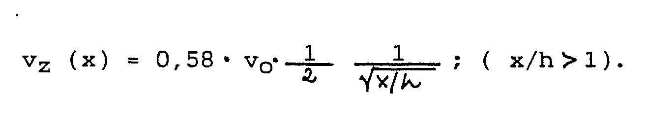
- the inflow speed in the filter is evenly distributed over the entire filter surface, while in the wall jet the inflow speed v z increases corresponding to v z ⁇ 1 / ⁇ x towards the blowing nozzle.
- the free jet formulas can only be used as a first approximation. In principle, it is a wall jet with only one free inflow surface for the vapor flow. With the formulas given above, only a rough first interpretation of the blowing and suction surface geometry is possible. The conditions can be fine-tuned experimentally using a defined hood.
- the wall jet principle according to the present invention results in an aerodynamic vapor screen in the form of a vortex which arises at the front hood edge from the interaction of the wall jet with an additional weaker free jet or vortex jet.
- This weaker free jet is generated with the help of a small slot, which is called the swirl nozzle, and which is approximately perpendicular to the blow slot.
- the interaction of the two rays, namely the wall jet and the vortex jet creates a vortex that lies below the front hood edge and whose direction of rotation points downwards and inwards from the front hood edge.
- This vortex acts beyond the edge of the hood, thus capturing the haze that blows past the edge of the hood and guides it to the blowing jet, which transports it to the filter surface.
- the slot width b w of the swirl nozzle is approximately one third to one quarter of the blow slot width.
- the air from the swirl nozzle is taken from the supply duct in front of the blowing nozzle, which is formed between the fan and the front hood limitation. Blowing nozzle and swirl nozzle thus work at the same total pressure.
- the position of the vortex core can be controlled via the width of the vortex nozzle. If the width b w of the nozzle is small compared to the width of the blowing nozzle, the core is very close to the blowing jet. With a width of the blow jet nozzle of 6 mm and a width of the vortex nozzle of 2 mm, the primary vortex core is approximately 2 cm below the hood. Flow observations with smoke or strong cooking vapor show that the vortex is generated according to the described method and that it also detects the cooking vapor outside the hood. The core of the cooking vapor vortex is somewhat lower than the core of the primary air vortex.
- the hood is equipped with a suction fan, of which about 25% of the air on the pressure side is used for the wall jet. The remaining 75% are discharged outside via the exhaust air duct.
- the blowing air is guided in a hollow chamber or a hollow channel to the front edge of the hood, where it exits via the blowing nozzle and the vortex nozzle.
- the rising mist is captured by the vortex and the wall jet and transported very quickly to the rear filter, where it is captured by the fan with the additionally drawn in air.
- the flow continuity at the filter inlet is important. That is, the air flow of the wall jet at the filter inlet must not be greater than the conveying capacity of the fan, taking into account the flow resistance of the filter. If the blown air flow is too large, part of the air flow sweeps past the filter and down the rear wall.
- a hood edge vortex With a hood edge vortex according to the invention, the escape of the vapor outside the hood area is prevented and cooking vapor, which rises from the stove or the source of the vapor from outside the hood, is detected and fed to the extractor hood.
- the wall jet With the help of the wall jet, due to the high speed of this jet, the entire rising haze is detected and fed to the filter. With an appropriate design, the haze does not penetrate through the wall jet, but is taken along by it, so that on the wall side of the jet, ie the underside of the extractor hood, no precipitation of water vapor or grease can be detected even with strong haze development at the haze source. In contrast to normal hoods, the underside and front of the hood remain dry and clean. The formation of water vapor, which condenses on the vapor screen of a normal hood in the event of strong vapor development, is caused by the hood vortex completely avoided. The underside of the hood is always exposed to the cleaned air of the jet and therefore contaminates much more slowly than with normal hoods with pure suction operation.
- Known extractor hoods capture the haze by suction flow.
- the stove 1 has a hotplate 2 with saucepan 3 as a source of haze.
- the vapor flow 4 runs upward to the filter 6 provided in the extractor hood 5, above which a fan 7 is arranged.
- 8 shows the suction chamber, 9 the pressure chamber inside the extractor hood 5.
- the filtered air passes from the blower 7 through the exhaust line 10 either into the open or as purified recirculated air back into the room.
- the speed of the rising vapor flow is indicated by arrow 11 with 12 the suction flow and with arrow 13 the exhaust air.
- 14 denotes the underside of the extractor hood 5, 15 an intermediate floor, which separates the filter 6 from the fan 7.
- the speed of the vapor flow 11 (V D ) is many times greater than the speed of the suction flow 12 (V F ).
- the extractor hood 16 has a filter 17 which is arranged in the rear area of the extractor hood and positioned obliquely between the rear area of the hood underside and the hood rear, forming part of the hood underside.
- the fan 18 is arranged inclined to the filter 17. With 19 the suction chamber, with 20 the pressure chamber and with 21 the exhaust air duct. Furthermore, 11 denotes the vapor flow, 22 the wall jet on the underside of the hood, 23 the suction flow, 24 the exhaust air and 25 the blown air in the hood.
- a blowing nozzle 26 is formed at the front, lower hood end 27. 28 shows the underside of the hood, which is the wall delimiting the flow of the wall jet 22, and 29 the intermediate floor.
- the intermediate floor 28 is formed with a rounded front end 30 within the hood 16; the extractor hood 16 has at the front end an approximately vertically extending end face 31 and an adjoining, approximately horizontally extending lower limit 32.
- the elements 30, 31 and 32 form the deflection channel for the blown air flow 25 within the hood and the blower nozzle 26, from which the wall jet 22 emerges, the lower limit of which is designated by 33.
- With 34 partial flows of the suction flow 11 are shown by arrows.
- the velocity distribution of the wall jet 22 is given in FIG. 3 in the form of the volume flow V ⁇ .
- Fig. 4 shows the distribution of the inflow speed in the filter, namely a) with suction flow and b) with blowing flow.
- the suction effect is distributed uniformly over the entire filter surface.
- the suction effect at the blow-out point on the front of the hood is greatest and decreases according to curve 36 with an increasing aspect ratio x / L from curve 36.
- the mean inflow V ⁇ / L is the same in both cases.
- a hood edge vortex which is designated by 37, is formed in the front hood region to support the detection of the vapor with a blowing flow.
- the underside 32 of the blowing nozzle 26 has a slot 38 through which a part 39 of the blowing air 25 emerges from the hood 16 approximately vertically downwards, while the larger part in the form of the wall jet 22 is directed against the filter 17.
- the jet 39 emerging from the vortex nozzle 32 forms, together with the wall jet 22, a vortex whose center 40 is formed just below the hood 16;
- a vortex flow 37 is formed around this vortex core 40, which is directed clockwise in the indicated direction of view and introduces into the wall jet 22 and is then transported together with this to the filter 17.
- the slot width of the swirl nozzle 38 is a fraction of the slot width of the blow nozzle, about a third to a quarter.
- the position of the vortex core 40 can be controlled via the width of the vortex nozzle.
- the nozzle opening of the swirl nozzle 38 can preferably be designed to be adjustable, so that the ratio of the slot width from the swirl nozzle to the blowing nozzle is variable.
- Fig. 6 shows a practical embodiment of an extractor hood with wall jet and hood edge swivel.
- the hood consists of a rear wall 41, a top wall 42 with a recess 43 and a flange 44 for the exhaust air duct, approximately one vertically arranged partial front wall 45, an inclined wall 46 extending from wall 45 to the front, an approximately vertical wall 47 representing the lower front boundary of the hood, a bottom wall 48 and an oblique between bottom wall 48 and rear wall 41 which receive filter 17 Wall and side walls, not shown.
- the fan 49 is separated from the filter area by an intermediate wall 50, so that a suction chamber 51 is formed between the intermediate wall 50 and the filter and a pressure chamber 52 is formed above the intermediate wall.
- the intermediate wall 50 is designed as a spiral housing surrounding the fan 49, which has an opening 53 to the front of the hood, through which the blowing air 25 can reach the blowing nozzle and the vortex nozzle.
- the blown air flows through an air duct formed by the hood housing, the shape of which is designed such that the blown flow reaches the blower nozzle or the vortex nozzle in a defined manner.
- the embodiment shown can be easily converted into an air hood.
- the exhaust air (as usual with other switchable hoods) is led into the kitchen with the help of a switch flap, not shown.
Landscapes
- Engineering & Computer Science (AREA)
- Chemical & Material Sciences (AREA)
- Combustion & Propulsion (AREA)
- Mechanical Engineering (AREA)
- General Engineering & Computer Science (AREA)
- Ventilation (AREA)
- Respiratory Apparatuses And Protective Means (AREA)
- Cleaning In General (AREA)
- Separation, Recovery Or Treatment Of Waste Materials Containing Plastics (AREA)
- Processing And Handling Of Plastics And Other Materials For Molding In General (AREA)
Abstract
Description
- Die Erfindung betrifft ein Verfahren und eine Einrichtung zum Absaugen von Dämpfen und Dunststoffen, die an Küchenherden, Kochstellen oder Dunstquellen industrieller Art entstehen. Insbesondere bezieht sich die Erfindung auf Küchendunstabzugshauben.
- Zur Beseitigung von Dämpfen und Dunststoffen werden über den Dunstquellen Dunstabzugshauben angeordnet, die die Dämpfe und Dunststoffe mittels Gebläse durch eine Filterfläche hindurch ansaugen und die gefilterte Luft entweder in den Arbeitsraum zurückführen (Umlufthaube) oder über einen Abluftkanal in das Freie fördern (Ablufthaube). Allen herkömmlichen Dunstabzugshauben ist gemeinsam, den Dampf bzw. Dunst über eine Saugströmung an die Filterfläche heranzuführen. Da der Kochdampf durch die auf ihn einwirkenden thermischen Auftriebskräfte stark nach oben beschleunigt wird und dabei eine starke Eigendynamik entwickelt, ist es sehr schwierig, den Dampf bzw. Dunst über eine Saugströmung vollständig zu erfassen, da hierzu entweder eine Haube mit einer Querschnittsfläche, die wesentlich größer als die Kochfläche ist, oder ein Gebläse mit extrem hoher Saugleistung benötigt würde.
- Zur Veranschaulichung der an derartigen Abzugshauben herrschenden Geschwindigkeiten und Bedingungen gelten nachstehende Überlegungen:
- Heißer Wasserdampf besitzt bei 100° C eine Dichte ρ D, die etwa die Hälfte der Dichte ρ L der umgebenden Luft beträgt. Auf den Dampf wirkt eine thermische Auftriebskraft, die ihn mit einer Beschleunigung b ≈ 9,81 m/s² nach oben zu treiben versucht. Dieser Beschleunigung wirkt am Rand des Dunststromes die Reibung mit der umgebenden Luft entgegen, die die Randbereiche verzögert und dadurch eine pilzförmige Dampfschwadenströmung verursacht.
- Der frei aufsteigende Wasserdampf erreicht z.B. nach einer Wegstrecke von 0,5 m eine theoretische Aufwärtsgeschwindigkeit von vD = 3,1 m/s. Die Beobachtung von aufsteigendem Kochdampf bestätigt dies und zeigt, daß die Dampfschwaden eine starke Eigendynamik mit schwankender Aufsteigrichtung entwickeln.
- Die Saugströmung üblicher Dunstabzugshauben ist zu schwach, um dieser Eigendynamik entgegenzuwirken und den Dunst vollständig zur Filterfläche zu führen. Die nachstehende Überlegung zeigt, daß es vor der Filterfläche normaler Hauben zu einem Dunststau kommt. Hierbei sei zugrunde gelegt, daß die Filterfläche F = 0,2 m² und der Durchsatz V des Gebläses = 300 m³/h betrage. Die Eintrittsgeschwindigkeit v der Luft in den Filter ergibt sich damit zu:

- Der kochende Wasserdampf besitzt nach einer Wegstrecke von 0,5 m eine Aufwärtsgeschwindigkeit von 3,1 m/s. Er muß deshalb vor der Filterfläche gestaut werden, da er diese Filterfläche nur mit der vorstehend ermittelten Geschwindigkeit von 0,42 m/s durchströmen kann. Bei diesem Stau entweicht ohne ausreichend großen Stauraum ein Teil des Kochdampfes über die Ränder der Dunstabzugshaube in die Küche. Um dies zu verhindern, wurden verschiedentlich Frischluftschleier vorgeschlagen, die vom Haubenrand nach abwärts gerichtet sind. Entsprechende Vorschläge sind beispielsweise den folgenden DE-OSen 22 59 670, 19 63 456, 19 24 345, und 16 04 293 zu entnehmen.
- Aus dem DBGM 85 34 453 ist eine Dunstabzugshaube mit etwa rechteckförmigem Querschnitt mit getrennter Zuleitung und Saugleitung bekannt. Die aus der Zuleitung in die durch eine geneigte Trennwand und die vertikale Seitenwand gebildete Zuführkammer gelangende Luft wird über einen ausgerundeten Strömungskanal und eine Austrittsöffnung als Freistrahl, d. h. als Strahl ohne seitliche Begrenzung, gegen das auf der gegenüberliegenden Haubenseite schräg angestellte, im Haubeninneren angeordnete Filter gerichtet. Der aus der Austrittsöffnung austretende ebene Freistrahl breitet sich dabei kegelförmig schräg nach oben in Richtung zum Filter ungeführt und ohne Randbegrenzung aus, und kann durch Umgebungseinflüsse abgelenkt werden, so daß eine eindeutige Führung des Strahles nicht erzielt wird, Randströme vom Sauggebläse nicht erfaßt werden und die Effektivität der Haube reduziert wird.
- Um Dunstausbrüche in die Küche zu verhindern, kann die Gebläseleistung gesteigert werden, was jedoch normalerweise einen sehr hohen Geräuschpegel ergibt, oder es können ausklappbare Schirme am Haubenvorderrand eingebaut werden, deren Wirksamkeit jedoch relativ begrenzt ist, die die Sicht zur Kochfläche wesentlich verschlechtern, und die durch Wasserdampf und Fettkondensation relativ schnell verschmutzen.
- Aufgabe der Neuerung ist es, ein Verfahren und eine Einrichtung zum Absaugen von Dunst oder Dampf zu schaffen, damit der von der Dunstquelle aufsteigende Dunststrom vollständig in der Einrichtung erfaßt und ein Entweichen in die Küche bzw. den umgebenden Raum verhindert wird; gleichzeitig soll dabei die Leistung des Absauggebläses und damit der Lärmpegel so gering wie möglich und die Effektivität der Haube so groß wie möglich gehalten werden.
- Diese Aufgabe wird gemäß der Erfindung mit den Merkmalen des Kennzeichens des Anspruches 1 erreicht. Weitere Ausgestaltungen der Erfindung sind Gegenstand der Unteransprüche.
- Mit vorliegender Erfindung wird somit vorgeschlagen, einen horizontalen Luftstrahl vom vorderen Haubenrand zu der am hinteren Haubenende liegenden Filterfläche zu blasen. Dieser Luftstrahl wird als Blasluft dem Gebläse entnommen, am vorderen Haubenrand umgelenkt und durch einen Schlitz am vorderen Haubenrand entlang der Haubenunterseite in Form eines Wandstrahles geführt. Dieser Wandstrahl erfaßt den vertikal aufsteigenden Dunststrom und führt ihn der Filterfläche zu. Der Wandstrahl wirkt entsprechend einem aerodynamischen Förderband; die Geschwindigkeit des Wandstrahles ist höher als die Geschwindigkeit des aufsteigenden Kochdunstes, der bei der Erfassung an der Haubenunterseite nicht verzögert wird. Durch die Verwendung eines derartigen Wandstrahles wird der Luftstrom zum Filter durch die Haubenunterseite gezielt geführt; der Wandstrahl saugt nur an der freien Seite, nämlich an der der Dunstquelle zugewandten Unterseite des Luftstromes umgebende Luft an. Durch die Wand wird der Wandstrahl sicher geführt, er haftet fest an der Wand an und kann selbst größeren Umlenkungen an der Wand folgen. Des weiteren ist der Wandstrahl gegenüber Einflüssen aus der Umgebung wesentlich unempfindlicher als ein Freistrahl. Schließlich ist der Wandstrahl notwendig, um auf Grund des Zusammenwirkens mit dem Luftstrahl aus der Wirbeldüse den Wirbel zu erzeugen.
- Die Fördermenge des hinter der Filterfläche angeordnten Sauggebläses ist so bemessen, daß es mindestens die Luftmenge des Wandstrahles an der Filtereintrittsfläche fördert. Infolge der Saugwirkung des Strahles steigt der anfänglich ausgeblasene Luftstrom Vo kontinuierlich bis zur Filterfläche hin an. Die Blasluftmenge Vo kann entweder dem Sauggebläse auf der Druckseite entnommen oder über ein kleines zusätzliches Gebläse über den Filter angesaugt, oder als zusätzliches Gebläse am vorderen Haubenrand in Form eines Druck-Blasstrahles dem Filter zugeführt werden. Wird der Wandstrahl über eine Schlitzdüse erzeugt, können nach der Freistrahltheorie die wichtigsten Strömungsgrößen längs des Strahles überschlägig berechnet werden, wobei gilt:
- Der Volumenstrom im Strahl nimmt wie folgt zu:

- Der Strahl verbreitert sich mit zunehmender Lauflänge und seine Maximalgeschwindigkeit nimmt kontinuierlich ab.
- Die Abnahme dieser Maximalgeschwindigkeit V im Strahl beträgt

- Die Strahlbreite beträgt bs = x · tg ϑ , wobei ϑ ≈ 14°.
- Die Strahlverbreitung kann durch den Winkel ϑ abgeschätzt werden, der in etwa den Strahlrand definiert, an dem die Geschwindigkeit nur 10% des Maximalwertes beträgt (ϑ ≈ 14°).
- Damit der gesamte Wandstrahl erfaßt werden kann, ist die Breite der Filterfläche der Strahlbreite anzupassen. Im Vergleich zu einer normalen Saugströmung durch ein Filter, bei der die Saugwirkung gleichförmig über die Filterfläche verteilt ist, bietet der Wandstrahl den Vorteil, daß die Saugwirkung an der an der Haubenvorderseite liegenden Blasdüse am größten ist.
- Die Zuströmgeschwindigkeit im Filter ist über die gesamte Filterfläche gleichmäßig verteilt, während im Wandstrahl die Zuströmgeschwindgkeit vz entsprechend vz ≈ 1/√x zur Blasdüse hin zunimmt. Im einzelnen gilt:
- Da der Blasstrahl an der Haubenunterseite einseitig an einer Wand geführt wird, können die Freistrahlformeln nur in erster Näherung benutzt werden. Im Prinzip handelt es sich um einen Wandstrahl mit nur einer freien Zuströmfläche für den Dunststrom. Mit den vorstehend angegebenen Formeln ist nur eine grobe erste Auslegung der Blas- und Saugflächengeometrie möglich. Eine Feinabstimmung der Verhältnisse ist experimentell anhand einer definierten Haube durchzuführen.
- Bei herkömmlichen Dunstabzugshauben entweicht am vorderen Haubenbereich sehr häufig Dunst. Um ein derartiges Entweichen von Dunst zu verhindern, sind bereits mechanische Abschirmungen, sogenannte Wrasenschirme eingesetzt worden.
- Im Gegensatz hierzu ergibt sich mit dem Wandstrahlprinzip nach vorliegender Erfindung ein aerodynamischer Wrasenschirm in Form eines Wirbels, der am vorderen Haubenrand aus dem Zusammenwirken des Wandstrahles mit einem zusätzlichen schwächeren Freistrahl bzw. Wirbelstrahl entsteht. Dieser schwächere Freistrahl wird mit Hilfe eines kleinen Schlitzes, der als Wirbeldüse bezeichnet wird, und der etwa senkrecht zum Blasschlitz steht, erzeugt. Durch Zusammenwirken der beiden Strahlen, nämlich des Wandstrahles und des Wirbelstrahles, entsteht ein Wirbel, der unterhalb des vorderen Haubenrandes liegt und dessen Drehrichtung vom vorderen Haubenrand nach unten und nach innen zeigt. Dieser Wirbel wirkt über den Haubenrand hinaus, er erfaßt damit den Dunst, der am Haubenrand vorbeistreicht, und führt ihn zum Blasstrahl, der ihn zur Filterfläche weitertransportiert.
- Die Schlitzbreite bw der Wirbeldüse beträgt etwa ein Drittel bis ein Viertel der Blasschlitzbreite. Die Luft der Wirbeldüse wird vor der Blasdüse dem Zuführkanal entnommen, der zwischen Gebläse und vorderer Haubenbegrenzung ausgebildet ist. Blasdüse und Wirbeldüse arbeiten somit bei demselben Gesamtdruck.
- Die Lage des Wirbelkernes kann über die Breite der Wirbeldüse gesteuert werden. Ist die Breite bw der Düse klein gegenüber der Breite der Blasdüse, liegt der Kern sehr nahe dem Blasstrahl. Bei einer Breite der Blasstrahldüse von 6 mm und einer Breite der Wirbeldüse von 2 mm liegt der primäre Wirbelkern etwa 2 cm unterhalb der Haube. Durch Strömungsbeobachtungen mit Rauch oder starkem Kochdunst läßt sich zeigen, daß der Wirbel nach dem geschilderten Verfahren erzeugt wird und daß er den Kochdunst auch außerhalb der Haube erfaßt. Der Kern des Kochdunstwirbels liegt dabei etwas tiefer als der Kern des primären Luftwirbels.
- Bei einer speziellen Ausführungsform der Erfindung ist die Haube mit einem Sauggebläse ausgestattet, von dem auf der Druckseite etwa 25 % der Luft für den Wandstrahl verwendet werden. Die restlichen 75 % werden über die Abluftleitung ins Freie abgeführt. Die Blasluft wird in einer Hohlkammer bzw. einem Hohlkanal zum vorderen Haubenrand geführt, wo sie über die Blasdüse und die Wirbeldüse austritt. Der aufsteigende Dunst wird vom Wirbel und vom Wandstrahl erfaßt und sehr schnell zum rückwärtigen Filter transportiert, wo er vom Gebläse mit der zusätzlich angesaugten Luft erfaßt wird.
- Für eine einwandfreie Wirkung des erfindungsgemäßen Verfahrens ist die Strömungskontinuität am Filtereintritt von Bedeutung, d. h., der Luftstrom des Wandstrahles am Filtereintritt darf nicht größer als die Förderkapazität des Gebläses sein, wobei der Strömungswiderstand des Filters zu berücksichtigen ist. Ist der Blasluftstrom zu groß, streicht ein Teil des Luftstromes am Filter vorbei und an der rückwärtigen Wand nach unten.
- Mit einem Haubenrandwirbel nach der Erfindung wird das Entweichen des Dunstes außerhalb des Haubenbereiches verhindert und zusätzlich Kochdunst, der vom Herd bzw. der Dunstquelle aus außerhalb der Haube hoch steigt, erfaßt und der Dunstabzugshaube zugeführt.
- Mit Hilfe des Wandstrahles wird aufgrund der hohen Geschwindigkeit dieses Strahles der gesamte aufsteigende Dunst erfaßt und dem Filter zugeführt. Bei entsprechender Auslegung dringt der Dunst nicht durch den Wandstrahl hindurch, sondern wird von ihm mitgenommen, so daß an der Wandseite des Strahles, d. h. der Unterseite der Abzugshaube, selbst bei starker Dunstentwicklung an der Dunstquelle kein Niederschlag von Wasserdampf oder Fett festzustellen ist. Die Haubenunterseite und die Haubenvorderseite bleiben im Gegensatz zu normalen Hauben trocken und sauber. Die Ausbildung von Wasserdampf, der am Wrasenschirm einer normalen Haube bei starker Dunstentwicklung kondensiert, wird durch den Haubenrandwirbel völlig vermieden. Die Haubenunterseite ist stets der gereinigten Luft des Strahles ausgesetzt und verschmutzt deshalb wesentlich langsamer als bei normalen Hauben mit reinem Saugbetrieb.
- Nachstehend wird die Erfindung in Verbindung mit der Zeichnung anhand von Ausführungsbeispielen erläutert. Es zeigt:
- Fig. 1 das Prinzip einer bekannten Dunstabzugshaube über einer Dunstquelle,
- Fig. 2 das Prinzip der erfindungsgemäßen Dunstabzugshaube mit Blasströmung, die als Wandstrahl geführt wird, über einer Dunstquelle,
- Fig. 3 eine detaillierte Darstellung der Strömung des Wandstrahles nach der Erfindung an der Dunstabzugshaube,
- Fig. 4 eine schematische Darstellung der Verteilung der Zuströmgeschwindigkeit am Absaugfilter und bei der Blasströmung des Wandstrahles,
- Fig. 5 eine weitere Ausgestaltung der Erfindung nach Fig. 3 mit Haubenrandwirbel, und
- Fig. 6 eine spezielle Ausführungsform der erfindungsgemäßen Dunstabzugshaube.
- Bekannte Dunstabzugshauben erfassen den Dunst durch Saugströmung. In Fig. 1 weist der Herd 1 eine Kochplatte 2 mit Kochtopf 3 als Dunstquelle auf. Die Dunstströmung 4 verläuft nach oben zu dem in der Dunstabzugshaube 5 vorgesehenen Filter 6, über dem ein Gebläse 7 angeordnet ist. Mit 8 ist der Saugraum, mit 9 der Druckraum innerhalb der Dunstabzugshaube 5 dargestellt. Die gefilterte Luft gelangt vom Gebläse 7 durch die Abluftleitung 10 entweder ins Freie oder als gereinigte Umluft wieder in den Raum. Mit Pfeil 11 ist die Geschwindigkeit des aufsteigenden Dunststromes bezeichnetm mit 12 die Saugströmung und mit Pfeil 13 die Abluft. 14 bezeichnet die Unterseite der Dunstabzugshaube 5, 15 einen Zwischenboden, der das Filter 6 vom Gebläse 7 trennt. Die Geschwindigkeit der Dunstströmung 11 (VD) ist dabei um ein Vielfaches größer als die Geschwindigkeit der Saugströmung 12 (VF).
- Bei der Dunsterfassung mit Hilfe von Blasströmung nach Fig. 2 sind Herd 1, Kochplatte 2 und Dunstquelle 3 entsprechend Fig. 1 dargestellt. Die Dunstabzugshaube 16 weist ein Filter 17 auf, das im rückwärtigen Bereich der Abzugshaube und schräg angestellt zwischen dem hinteren Bereich der Haubenunterseite und der Haubenrückseite, einen Teil der Haubenunterseite bildend, angeordnet ist. Das Gebläse 18 ist, dem Filter 17 zugeordnet, geneigt angeordnet. Mit 19 ist der Saugraum, mit 20 der Druckraum und mit 21 die Abluftleitung bezeichnet. Ferner ist mit 11 die Dunstströmung, mit 22 der Wandstrahl auf der Haubenunterseite, mit 23 die Saugströmung, mit 24 die Abluft und mit 25 die Blasluft in der Haube bezeichnet. Eine Blasdüse 26 ist am vorderen, unteren Haubenende 27 ausgebildet. Mit 28 ist die Unterseite der Haube, die die die Strömung des Wandstrahles 22 begrenzende Wand ist, und mit 29 der Zwischenboden gezeigt.
- Die Dunsterfassung mit Hilfe der Strömung des Wandstrahles ist in Fig. 3 näher dargestellt. Hierbei ist innerhalb der Abzugshaube 16 der Zwischenboden 28 mit einem gerundeten vorderen Ende 30 ausgebildet; die Abzugshaube 16 weist am vorderen Ende eine etwa vertikal verlaufende Stirnfläche 31 und eine daran anschließende, etwa horizontal verlaufende untere Begrenzung 32 auf. Die Elemente 30, 31 und 32 bilden den Umlenkkanal für die Blasluftströmung 25 innerhalb der Haube und die Blasdüse 26, aus der der Wandstrahl 22 austritt, dessen untere Begrenzung mit 33 bezeichnet ist. Mit 34 sind Teilströme des Saugstromes 11 durch Pfeile dargestellt. Des weiteren ist in Fig. 3 die Geschwindigkeitsverteilung des Wandstrahles 22 in Form des Volumenstromes V̇ angegeben.
- Fig. 4 zeigt die Verteilung der Zuströmgeschwindigkeit im Filter, und zwar a) mit Saugströmung und b) mit Blasströmung. Im Falle der reinen Saugströmung bei bekannten Dunstabzugshauben ist die Saugwirkung gleichförmig über die gesamte Filterfläche verteilt. Die Kurve 35 ist eine Gerade mit dem Wert v(x) / V̇/L = 1. Bei der mit Blasströmung arbeitenden Dunstabzugshaube ist die Saugwirkung an der Ausblasstelle an der Haubenvorderseite am größten und nimmt nach der Kurve 36 mit zunehmendem Längenverhältnis x / L nach der Kurve 36 ab. Der mittlere Zustrom V̇/ L ist dabei in beiden Fällen gleich.
- Bei der Ausführungsform nach Fig. 5 ist zur Unterstützung der Dunsterfassung mit Blasströmung ein Haubenrandwirbel im vorderen Haubenbereich ausgebildet, der mit 37 bezeichnet ist. Die Unterseite 32 der Blasdüse 26 weist hierzu einen Schlitz 38 auf, durch den ein Teil 39 der Blasluft 25 etwa senkrecht nach abwärts aus der Haube 16 austritt, während der größere Teil in Form des Wandstrahles 22 gegen das Filter 17 gerichtet wird. Der aus der Wirbeldüse 32 austretende Strahl 39 bildet zusammen mit dem Wandstrahl 22 einen Wirbel, dessen Zentrum 40 knapp unterhalb der Haube 16 ausgebildet ist; um diesen Wirbelkern 40 herum bildet sich eine Wirbelströmung 37 aus, die bei der angegebenen Blickrichtung im Uhrzeigersinn gerichtet ist und in den Wandstrahl 22 einführt und dann zusammen mit diesem zum Filter 17 weitertransportiert wird. Dieser Wirbel erfaßt den aufsteigenden Dunst 4 auch noch außerhalb der Haube und führt ihn dem Blasstrahl zu. Die Schlitzbreite der Wirbeldüse 38 ist ein Bruchteil der Schlitzbreite der Blasdüse, etwa ein Drittel bis ein Viertel. Die Lage des Wirbelkernes 40 kann über die Breite der Wirbeldüse gesteuert werden. Vorzugsweise kann die Düsenöffnung der Wirbeldüse 38 einstellbar ausgeführt sein, so daß das Verhältnis der Schlitzbreite von Wirbeldüse zu Blasdüse variabel ist.
- Fig. 6 zeigt eine praktische Ausführungsform einer Dunstabzugshaube mit Wandstrahl und Haubenrandwirbel. Die Haube besteht aus einer Rückwand 41, einer Deckwand 42 mit Ausnehmung 43 und Flansch 44 für die Abluftleitung, einer etwa vertikal angeordneten Teilvorderwand 45, einer von der Wand 45 sich nach vorne erstreckenden geneigten Wand 46, einer die vordere untere Begrenzung der Haube darstellenden, etwa vertikalen Wand 47, einer Bodenwand 48 und einer schrägen zwischen Bodenwand 48 und Rückwand 41 verlaufenden, das Filter 17 aufnehmenden Wand sowie nicht dargestellten Seitenwänden. Im Inneren der Dunstabzugshaube ist das Gebläse 49 durch eine Zwischenwand 50 vom Filterbereich getrennt, so daß zwischen der Zwischenwand 50 und dem Filter ein Saugraum 51 und oberhalb der Zwischenwand ein Druckraum 52 ausgebildet wird. Die Zwischenwand 50 ist dabei als das Gebläse 49 umgebendes Spiralgehäuse ausgebildet, das zur Haubenvorderseite eine Öffnung 53 besitzt, durch die die Blasluft 25 an die Blasdüse und die Wirbeldüse gelangen kann. Die Blasluft strömt dabei durch einen durch das Haubengehäuse ausgebildeten Luftkanal, dessen Formgebung so ausgelegt ist, daß die Blasströmung in definierter Weise an die Blasdüse bzw. die Wirbeldüse gelangt.
- Die gezeigte Ausführungsform kann auf einfache Weise in eine Umlufthaube umgestaltet werden. Hierzu wird mit Hilfe einer nicht dargestellten Umschaltklappe die Abluft (wie bei anderen umschaltbaren Hauben üblich) in die Küche geleitet.
Claims (12)
dadurch gekennzeichnet, daß am Boden der Abzugshaube ein Wandstrahl erzeugt wird, der unmittelbar unterhalb der Bodenfläche der Abzugshaube etwa horizontal geführt und einem im Weg der Blasluftströmung angeordneten Filter zugeführt wird, derart, daß der etwa vertikale Dunststrom von der etwa horizontalen Blasluftströmung mitgenommen wird.
Priority Applications (1)
| Application Number | Priority Date | Filing Date | Title |
|---|---|---|---|
| AT90109564T ATE93042T1 (de) | 1989-06-09 | 1990-05-19 | Verfahren und einrichtung zum absaugen von daempfen und dunststoffen. |
Applications Claiming Priority (2)
| Application Number | Priority Date | Filing Date | Title |
|---|---|---|---|
| DE3918870 | 1989-06-09 | ||
| DE3918870A DE3918870C2 (de) | 1989-06-09 | 1989-06-09 | Verfahren und Einrichtung zum Absaugen von Dämpfen und Dunststoffen |
Publications (2)
| Publication Number | Publication Date |
|---|---|
| EP0401583A1 true EP0401583A1 (de) | 1990-12-12 |
| EP0401583B1 EP0401583B1 (de) | 1993-08-11 |
Family
ID=6382428
Family Applications (1)
| Application Number | Title | Priority Date | Filing Date |
|---|---|---|---|
| EP90109564A Expired - Lifetime EP0401583B1 (de) | 1989-06-09 | 1990-05-19 | Verfahren und Einrichtung zum Absaugen von Dämpfen und Dunststoffen |
Country Status (6)
| Country | Link |
|---|---|
| US (1) | US5050581A (de) |
| EP (1) | EP0401583B1 (de) |
| JP (1) | JP2868289B2 (de) |
| AT (1) | ATE93042T1 (de) |
| DE (2) | DE3918870C2 (de) |
| ES (1) | ES2043175T3 (de) |
Cited By (8)
| Publication number | Priority date | Publication date | Assignee | Title |
|---|---|---|---|---|
| EP0491146B1 (de) * | 1990-12-19 | 1995-08-02 | Bosch-Siemens HausgerÀ¤te GmbH | Luftreinigungsgerät, insbesondere Küchen-Dunstabzugshaube |
| WO2008148712A3 (en) * | 2007-06-06 | 2009-07-30 | Veljko Martic | Kitchen extractor hood with innovative design |
| EP1778418A4 (de) * | 2004-07-23 | 2009-09-02 | Halton Group Ltd Oy | Verbesserungen zur steuerung von abgassystemen |
| DE102012012551A1 (de) * | 2012-06-23 | 2013-12-24 | Heinrich Wagener | Lüftungsanordnung mit einer Dunstabzugshaube |
| NL2011635C2 (en) * | 2013-10-17 | 2015-04-20 | Randolph Beleggingen B V | Kitchen air extraction canopy having a cavity with air guiding and directing delimiting wall. |
| DE202016004286U1 (de) | 2016-07-13 | 2016-08-12 | Heinrich Wagener | Lüftungsanordnung mit einer Dunstabzugshaube |
| US9494324B2 (en) | 2008-12-03 | 2016-11-15 | Oy Halton Group Ltd. | Exhaust flow control system and method |
| US10302307B2 (en) | 2007-08-28 | 2019-05-28 | Oy Halton Group Ltd. | Autonomous ventilation system |
Families Citing this family (25)
| Publication number | Priority date | Publication date | Assignee | Title |
|---|---|---|---|---|
| DE4203916C1 (de) * | 1992-02-11 | 1993-04-29 | Hannelore 8400 Regensburg De Roehl-Hager | |
| DE19613513A1 (de) | 1996-04-04 | 1997-10-09 | Roehl Hager Hannelore | Verfahren zum Eingrenzen, Erfassen und Absaugen von Dunst, Staub oder dergleichen sowie Einrichtung zur Durchführung des Verfahrens |
| DE19911850B4 (de) | 1999-03-17 | 2010-04-08 | Röhl-Hager, Hannelore | Verfahren und Vorrichtung zum Eingrenzen, Erfassen und Absaugen von Schadstoffen, insbesondere bei Dunstabzugshauben |
| DE19957962B4 (de) * | 1999-05-19 | 2009-01-29 | Röhl-Hager, Hannelore | Verfahren und Einrichtung zum Eingrenzen, Erfassen und Absaugen von fluiden Medien |
| DE10015666A1 (de) * | 1999-12-14 | 2001-06-28 | Georg Emanuel Koppenwallner | Verfahren und Einrichtung zum Erfassen, Trennen und Absaugen von fluiden Medien unter Verwendung von Frontalwirbelgeneratoren |
| AU2351401A (en) | 1999-12-14 | 2001-06-25 | Georg Emanuel Koppenwallner | Method and device for capturing, separating and aspirating fluids using frontal turbulence generators |
| JP4870307B2 (ja) * | 2000-01-10 | 2012-02-08 | オーワイ ハルトン グループ リミテッド | エアカーテンを備える排気フード |
| KR100347959B1 (en) * | 2001-12-28 | 2002-08-21 | Ecta Co Ltd | Ventilation hood for kitchen |
| US20040129263A1 (en) * | 2003-01-02 | 2004-07-08 | Chao-Cheng Chiang | Ventilator having an optimum air box |
| US20040149278A1 (en) * | 2003-01-30 | 2004-08-05 | Chun-Ying Lin | Kitchen ventilator with recirculation function |
| JP4495475B2 (ja) * | 2004-02-02 | 2010-07-07 | 富士工業株式会社 | Ihクッキングヒータ用のレンジフード |
| KR100608704B1 (ko) * | 2004-12-20 | 2006-08-08 | 엘지전자 주식회사 | 주방용 후드의 월제트 배기장치 |
| US7699051B2 (en) * | 2005-06-08 | 2010-04-20 | Westen Industries, Inc. | Range hood |
| US20070099558A1 (en) * | 2005-10-31 | 2007-05-03 | Oagley Howard J | Hood assembly |
| DE102007039635A1 (de) * | 2007-03-20 | 2008-09-25 | BSH Bosch und Siemens Hausgeräte GmbH | Dunstabzugshaube |
| US20080274683A1 (en) | 2007-05-04 | 2008-11-06 | Current Energy Controls, Lp | Autonomous Ventilation System |
| EP2787286A1 (de) | 2008-04-18 | 2014-10-08 | OY Halton Group, Ltd. | Abgasgerät, System und Verfahren für bessere Erfassung und Rückhaltung |
| US8505530B2 (en) * | 2009-11-19 | 2013-08-13 | Itw Food Equipment Group Llc | Commercial kitchen exhaust system |
| PL2969050T3 (pl) | 2013-03-15 | 2019-08-30 | Oy Halton Group Ltd. | Oczyszczanie oparów rozpylaną wodą z działaniem opartym na zapotrzebowaniu |
| KR102557926B1 (ko) * | 2016-11-07 | 2023-07-21 | 삼성전자주식회사 | 후드 겸용 조리기기 |
| CN107957085B (zh) * | 2017-11-27 | 2023-01-03 | 佛山市云米电器科技有限公司 | 一种可移动式油烟机 |
| JP6549811B1 (ja) * | 2018-10-02 | 2019-07-24 | 明彦 山口 | レンジフードやファンの汚染防止技術 |
| JP6687956B1 (ja) * | 2019-07-11 | 2020-04-28 | 明彦 山口 | レンジフードの排煙ダクトの汚染防止方法 |
| EA037076B1 (ru) * | 2019-08-12 | 2021-02-02 | Федеральное государственное бюджетное образовательное учреждение высшего образования "Петербургский государственный университет путей сообщения Императора Александра I" | Устройство для вентиляции воздуха над плитой для приготовления пищи |
| DE102022134182A1 (de) * | 2022-12-20 | 2024-06-20 | Südluft Systemtechnik GmbH | Lüftungshaube zur Erfassung von Wrasendämpfen und Kücheninstallation |
Citations (5)
| Publication number | Priority date | Publication date | Assignee | Title |
|---|---|---|---|---|
| US4043319A (en) * | 1975-09-18 | 1977-08-23 | Jensen Donald D | Exhaust hood |
| US4153044A (en) * | 1978-01-23 | 1979-05-08 | Nett Louis A | Backshelf ventilating hood |
| EP0163763A1 (de) * | 1984-06-06 | 1985-12-11 | Maysteel Corporation | Kompensierte Abzugshaube |
| DE8531520U1 (de) * | 1985-11-08 | 1986-01-02 | Rentschler, Peter, 7126 Sersheim | Lüftungsdecke zur Absaugung verbrauchter Luft aus einem Raum |
| EP0294006A1 (de) * | 1987-06-04 | 1988-12-07 | Philips Patentverwaltung GmbH | Dunstabzugshaube, insbesondere für Küchen |
Family Cites Families (6)
| Publication number | Priority date | Publication date | Assignee | Title |
|---|---|---|---|---|
| US3400649A (en) * | 1967-01-26 | 1968-09-10 | Donald D. Jensen | Ventilating system including fume removal means |
| US3513766A (en) * | 1968-06-24 | 1970-05-26 | Willard K Ahlrich | Ventilating hood |
| DE2531862A1 (de) * | 1975-07-17 | 1977-02-10 | Karl Dipl Ing Schmitt | Umluft-dunstabzugshaube |
| US4483316A (en) * | 1983-10-11 | 1984-11-20 | Alco Foodservice Equipment Company | Air ventilation system |
| DE8534453U1 (de) * | 1985-12-07 | 1986-01-23 | Rentschler Reven Lüftungssysteme GmbH, 7126 Sersheim | Dunstabzugshaube |
| DE8903530U1 (de) * | 1989-03-21 | 1989-05-03 | Rentschler Reven-Lüftungssysteme GmbH, 7126 Sersheim | Dunstabzugshaube |
-
1989
- 1989-06-09 DE DE3918870A patent/DE3918870C2/de not_active Expired - Fee Related
-
1990
- 1990-05-19 ES ES90109564T patent/ES2043175T3/es not_active Expired - Lifetime
- 1990-05-19 DE DE9090109564T patent/DE59002272D1/de not_active Expired - Fee Related
- 1990-05-19 AT AT90109564T patent/ATE93042T1/de not_active IP Right Cessation
- 1990-05-19 EP EP90109564A patent/EP0401583B1/de not_active Expired - Lifetime
- 1990-05-24 US US07/528,202 patent/US5050581A/en not_active Expired - Lifetime
- 1990-06-08 JP JP2148895A patent/JP2868289B2/ja not_active Expired - Fee Related
Patent Citations (5)
| Publication number | Priority date | Publication date | Assignee | Title |
|---|---|---|---|---|
| US4043319A (en) * | 1975-09-18 | 1977-08-23 | Jensen Donald D | Exhaust hood |
| US4153044A (en) * | 1978-01-23 | 1979-05-08 | Nett Louis A | Backshelf ventilating hood |
| EP0163763A1 (de) * | 1984-06-06 | 1985-12-11 | Maysteel Corporation | Kompensierte Abzugshaube |
| DE8531520U1 (de) * | 1985-11-08 | 1986-01-02 | Rentschler, Peter, 7126 Sersheim | Lüftungsdecke zur Absaugung verbrauchter Luft aus einem Raum |
| EP0294006A1 (de) * | 1987-06-04 | 1988-12-07 | Philips Patentverwaltung GmbH | Dunstabzugshaube, insbesondere für Küchen |
Cited By (12)
| Publication number | Priority date | Publication date | Assignee | Title |
|---|---|---|---|---|
| EP0491146B1 (de) * | 1990-12-19 | 1995-08-02 | Bosch-Siemens HausgerÀ¤te GmbH | Luftreinigungsgerät, insbesondere Küchen-Dunstabzugshaube |
| EP1778418A4 (de) * | 2004-07-23 | 2009-09-02 | Halton Group Ltd Oy | Verbesserungen zur steuerung von abgassystemen |
| US8038515B2 (en) | 2004-07-23 | 2011-10-18 | Oy Halton Group Ltd. | Control of exhaust systems |
| US10184669B2 (en) | 2004-07-23 | 2019-01-22 | Oy Halton Group Ltd | Control of exhaust systems |
| WO2008148712A3 (en) * | 2007-06-06 | 2009-07-30 | Veljko Martic | Kitchen extractor hood with innovative design |
| US10302307B2 (en) | 2007-08-28 | 2019-05-28 | Oy Halton Group Ltd. | Autonomous ventilation system |
| US9494324B2 (en) | 2008-12-03 | 2016-11-15 | Oy Halton Group Ltd. | Exhaust flow control system and method |
| DE102012012551A1 (de) * | 2012-06-23 | 2013-12-24 | Heinrich Wagener | Lüftungsanordnung mit einer Dunstabzugshaube |
| WO2013189598A1 (de) | 2012-06-23 | 2013-12-27 | Heinrich Wagener | Lüftungsanordnung mit einer dunstabzugshaube |
| NL2011635C2 (en) * | 2013-10-17 | 2015-04-20 | Randolph Beleggingen B V | Kitchen air extraction canopy having a cavity with air guiding and directing delimiting wall. |
| DE202016004286U1 (de) | 2016-07-13 | 2016-08-12 | Heinrich Wagener | Lüftungsanordnung mit einer Dunstabzugshaube |
| WO2018010971A1 (de) | 2016-07-13 | 2018-01-18 | Heinrich Wagener | Lüftungsanordnung mit einer dunstabzugshaube |
Also Published As
| Publication number | Publication date |
|---|---|
| DE3918870C2 (de) | 1995-06-29 |
| ES2043175T3 (es) | 1993-12-16 |
| JP2868289B2 (ja) | 1999-03-10 |
| US5050581A (en) | 1991-09-24 |
| ATE93042T1 (de) | 1993-08-15 |
| DE59002272D1 (de) | 1993-09-16 |
| DE3918870A1 (de) | 1990-12-13 |
| JPH0331634A (ja) | 1991-02-12 |
| EP0401583B1 (de) | 1993-08-11 |
Similar Documents
| Publication | Publication Date | Title |
|---|---|---|
| EP0401583B1 (de) | Verfahren und Einrichtung zum Absaugen von Dämpfen und Dunststoffen | |
| DE2607301C2 (de) | Dunstabzug | |
| DE3304262C2 (de) | Umluft-Abzugshaube | |
| EP1194721B1 (de) | Luftabsaugvorrichtung für einen arbeitsplatz | |
| DE10325007A1 (de) | Abzugshaube für einen Küchenherd | |
| EP3045824B1 (de) | Vorrichtung zum abziehen von abluft eines kochfelds | |
| DE4114329A1 (de) | Dunstabzugshaube mit luftschleier | |
| DE1924345A1 (de) | Dunstabzugshaube | |
| WO2004090425A2 (de) | Vorrichtung zum absaugen und zuführen von luft für eine kochstelle | |
| DE4203916C1 (de) | ||
| DE102017216456A1 (de) | Lüftungsvorrichtung für Kochfeld und Kochfeld mit Lüftungsvorrichtung | |
| EP4027063B1 (de) | Dunstabzugsvorrichtung, küchengerät mit kochfeld und dunstabzugsvorrichtung und verfahren zum betreiben einer dunstabzugsvorrichtung | |
| DE69402571T2 (de) | Dunstabzugshaube für Küchen | |
| DE3404775C1 (de) | Tischabsaugeschrank für schadstoffhaltige Arbeitsvorgänge und energiesparende Belüftung | |
| EP2829808B1 (de) | Dunstabzugshaube | |
| EP2677242B1 (de) | Vorrichtung zum ableiten von luft | |
| DE19950817A1 (de) | Dunstabzugsvorrichtung | |
| DE102017104934B4 (de) | Dunstabzug | |
| DE102008011934A1 (de) | Dunstabzugsvorrichtung und Verfahren zur Reinigung von Küchenluft | |
| DE7310557U (de) | Herd mit einer als Wrasenfang und Leitschirm ausgebildeten Abdeckhaube | |
| DE8303454U1 (de) | Umluft-dunstabzugshaube | |
| EP4165349A1 (de) | Dunstabzugsvorrichtung und küchenanordnung mit kochfeld und dunstabzugsvorrichtung | |
| WO2021122026A1 (de) | Erzeugung eines luftvorhangs zur verbesserung des wraseneinzugs bei dunstabzugshauben | |
| DE10203650A1 (de) | Verfahren und Vorrichtung zur Erfassung und zum Abzug von Küchendünsten | |
| DE102006023718A1 (de) | Dunstabzugsvorrichtung mit Zulüftung |
Legal Events
| Date | Code | Title | Description |
|---|---|---|---|
| PUAI | Public reference made under article 153(3) epc to a published international application that has entered the european phase |
Free format text: ORIGINAL CODE: 0009012 |
|
| AK | Designated contracting states |
Kind code of ref document: A1 Designated state(s): AT BE CH DE DK ES FR GB GR IT LI LU NL SE |
|
| 17P | Request for examination filed |
Effective date: 19901219 |
|
| 17Q | First examination report despatched |
Effective date: 19910613 |
|
| GRAA | (expected) grant |
Free format text: ORIGINAL CODE: 0009210 |
|
| AK | Designated contracting states |
Kind code of ref document: B1 Designated state(s): AT BE CH DE DK ES FR GB GR IT LI LU NL SE |
|
| PG25 | Lapsed in a contracting state [announced via postgrant information from national office to epo] |
Ref country code: NL Effective date: 19930811 Ref country code: GR Free format text: LAPSE BECAUSE OF FAILURE TO SUBMIT A TRANSLATION OF THE DESCRIPTION OR TO PAY THE FEE WITHIN THE PRESCRIBED TIME-LIMIT Effective date: 19930811 Ref country code: BE Effective date: 19930811 Ref country code: GB Effective date: 19930811 Ref country code: DK Effective date: 19930811 |
|
| REF | Corresponds to: |
Ref document number: 93042 Country of ref document: AT Date of ref document: 19930815 Kind code of ref document: T |
|
| REF | Corresponds to: |
Ref document number: 59002272 Country of ref document: DE Date of ref document: 19930916 |
|
| ET | Fr: translation filed | ||
| ITF | It: translation for a ep patent filed | ||
| REG | Reference to a national code |
Ref country code: ES Ref legal event code: FG2A Ref document number: 2043175 Country of ref document: ES Kind code of ref document: T3 |
|
| NLV1 | Nl: lapsed or annulled due to failure to fulfill the requirements of art. 29p and 29m of the patents act | ||
| GBV | Gb: ep patent (uk) treated as always having been void in accordance with gb section 77(7)/1977 [no translation filed] |
Effective date: 19930811 |
|
| PG25 | Lapsed in a contracting state [announced via postgrant information from national office to epo] |
Ref country code: AT Effective date: 19940519 |
|
| PG25 | Lapsed in a contracting state [announced via postgrant information from national office to epo] |
Ref country code: CH Effective date: 19940531 Ref country code: LU Free format text: LAPSE BECAUSE OF NON-PAYMENT OF DUE FEES Effective date: 19940531 Ref country code: LI Effective date: 19940531 |
|
| PLBE | No opposition filed within time limit |
Free format text: ORIGINAL CODE: 0009261 |
|
| STAA | Information on the status of an ep patent application or granted ep patent |
Free format text: STATUS: NO OPPOSITION FILED WITHIN TIME LIMIT |
|
| 26N | No opposition filed | ||
| EAL | Se: european patent in force in sweden |
Ref document number: 90109564.6 |
|
| REG | Reference to a national code |
Ref country code: CH Ref legal event code: PL |
|
| PGFP | Annual fee paid to national office [announced via postgrant information from national office to epo] |
Ref country code: SE Payment date: 20070508 Year of fee payment: 18 |
|
| PGFP | Annual fee paid to national office [announced via postgrant information from national office to epo] |
Ref country code: ES Payment date: 20070621 Year of fee payment: 18 |
|
| PGFP | Annual fee paid to national office [announced via postgrant information from national office to epo] |
Ref country code: IT Payment date: 20070525 Year of fee payment: 18 |
|
| PGFP | Annual fee paid to national office [announced via postgrant information from national office to epo] |
Ref country code: FR Payment date: 20070510 Year of fee payment: 18 |
|
| PGFP | Annual fee paid to national office [announced via postgrant information from national office to epo] |
Ref country code: DE Payment date: 20080516 Year of fee payment: 19 |
|
| REG | Reference to a national code |
Ref country code: FR Ref legal event code: ST Effective date: 20090119 |
|
| PG25 | Lapsed in a contracting state [announced via postgrant information from national office to epo] |
Ref country code: FR Free format text: LAPSE BECAUSE OF NON-PAYMENT OF DUE FEES Effective date: 20080602 |
|
| REG | Reference to a national code |
Ref country code: ES Ref legal event code: FD2A Effective date: 20080520 |
|
| PG25 | Lapsed in a contracting state [announced via postgrant information from national office to epo] |
Ref country code: IT Free format text: LAPSE BECAUSE OF NON-PAYMENT OF DUE FEES Effective date: 20080519 |
|
| PG25 | Lapsed in a contracting state [announced via postgrant information from national office to epo] |
Ref country code: ES Free format text: LAPSE BECAUSE OF NON-PAYMENT OF DUE FEES Effective date: 20080520 |
|
| PG25 | Lapsed in a contracting state [announced via postgrant information from national office to epo] |
Ref country code: DE Free format text: LAPSE BECAUSE OF NON-PAYMENT OF DUE FEES Effective date: 20091201 |
|
| PG25 | Lapsed in a contracting state [announced via postgrant information from national office to epo] |
Ref country code: SE Free format text: LAPSE BECAUSE OF NON-PAYMENT OF DUE FEES Effective date: 20080520 |