EP0401640A1 - Dispositif de connection électrique refroidi par eau, pour courant fort - Google Patents
Dispositif de connection électrique refroidi par eau, pour courant fort Download PDFInfo
- Publication number
- EP0401640A1 EP0401640A1 EP90110101A EP90110101A EP0401640A1 EP 0401640 A1 EP0401640 A1 EP 0401640A1 EP 90110101 A EP90110101 A EP 90110101A EP 90110101 A EP90110101 A EP 90110101A EP 0401640 A1 EP0401640 A1 EP 0401640A1
- Authority
- EP
- European Patent Office
- Prior art keywords
- socket
- contact
- contact ring
- ring
- pin part
- Prior art date
- Legal status (The legal status is an assumption and is not a legal conclusion. Google has not performed a legal analysis and makes no representation as to the accuracy of the status listed.)
- Granted
Links
- 238000003466 welding Methods 0.000 claims abstract description 11
- 230000000284 resting effect Effects 0.000 claims abstract 3
- 238000003032 molecular docking Methods 0.000 claims description 9
- 210000002105 tongue Anatomy 0.000 claims description 7
- 238000003780 insertion Methods 0.000 claims description 6
- 230000037431 insertion Effects 0.000 claims description 6
- 230000009467 reduction Effects 0.000 claims description 4
- 239000002184 metal Substances 0.000 claims description 2
- 238000006073 displacement reaction Methods 0.000 claims 1
- 230000013011 mating Effects 0.000 description 5
- XLYOFNOQVPJJNP-UHFFFAOYSA-N water Substances O XLYOFNOQVPJJNP-UHFFFAOYSA-N 0.000 description 4
- 230000008901 benefit Effects 0.000 description 2
- 238000010438 heat treatment Methods 0.000 description 2
- 238000007789 sealing Methods 0.000 description 2
- 230000005540 biological transmission Effects 0.000 description 1
- 238000010276 construction Methods 0.000 description 1
- 238000001816 cooling Methods 0.000 description 1
- 239000000498 cooling water Substances 0.000 description 1
- 230000008878 coupling Effects 0.000 description 1
- 238000010168 coupling process Methods 0.000 description 1
- 238000005859 coupling reaction Methods 0.000 description 1
- 230000005611 electricity Effects 0.000 description 1
- 230000002349 favourable effect Effects 0.000 description 1
- 238000009434 installation Methods 0.000 description 1
- 238000004080 punching Methods 0.000 description 1
- 230000008439 repair process Effects 0.000 description 1
- 238000000926 separation method Methods 0.000 description 1
- 239000007787 solid Substances 0.000 description 1
- 230000007704 transition Effects 0.000 description 1
Images


Classifications
-
- H—ELECTRICITY
- H01—ELECTRIC ELEMENTS
- H01R—ELECTRICALLY-CONDUCTIVE CONNECTIONS; STRUCTURAL ASSOCIATIONS OF A PLURALITY OF MUTUALLY-INSULATED ELECTRICAL CONNECTING ELEMENTS; COUPLING DEVICES; CURRENT COLLECTORS
- H01R13/00—Details of coupling devices of the kinds covered by groups H01R12/70 or H01R24/00 - H01R33/00
- H01R13/02—Contact members
- H01R13/10—Sockets for co-operation with pins or blades
- H01R13/11—Resilient sockets
-
- H—ELECTRICITY
- H01—ELECTRIC ELEMENTS
- H01R—ELECTRICALLY-CONDUCTIVE CONNECTIONS; STRUCTURAL ASSOCIATIONS OF A PLURALITY OF MUTUALLY-INSULATED ELECTRICAL CONNECTING ELEMENTS; COUPLING DEVICES; CURRENT COLLECTORS
- H01R13/00—Details of coupling devices of the kinds covered by groups H01R12/70 or H01R24/00 - H01R33/00
- H01R13/02—Contact members
- H01R13/15—Pins, blades or sockets having separate spring member for producing or increasing contact pressure
- H01R13/187—Pins, blades or sockets having separate spring member for producing or increasing contact pressure with spring member in the socket
-
- B—PERFORMING OPERATIONS; TRANSPORTING
- B23—MACHINE TOOLS; METAL-WORKING NOT OTHERWISE PROVIDED FOR
- B23K—SOLDERING OR UNSOLDERING; WELDING; CLADDING OR PLATING BY SOLDERING OR WELDING; CUTTING BY APPLYING HEAT LOCALLY, e.g. FLAME CUTTING; WORKING BY LASER BEAM
- B23K9/00—Arc welding or cutting
- B23K9/32—Accessories
- B23K9/323—Combined coupling means, e.g. gas, electricity, water or the like
-
- H—ELECTRICITY
- H01—ELECTRIC ELEMENTS
- H01R—ELECTRICALLY-CONDUCTIVE CONNECTIONS; STRUCTURAL ASSOCIATIONS OF A PLURALITY OF MUTUALLY-INSULATED ELECTRICAL CONNECTING ELEMENTS; COUPLING DEVICES; CURRENT COLLECTORS
- H01R2101/00—One pole
-
- H—ELECTRICITY
- H01—ELECTRIC ELEMENTS
- H01R—ELECTRICALLY-CONDUCTIVE CONNECTIONS; STRUCTURAL ASSOCIATIONS OF A PLURALITY OF MUTUALLY-INSULATED ELECTRICAL CONNECTING ELEMENTS; COUPLING DEVICES; CURRENT COLLECTORS
- H01R39/00—Rotary current collectors, distributors or interrupters
- H01R39/64—Devices for uninterrupted current collection
-
- H—ELECTRICITY
- H01—ELECTRIC ELEMENTS
- H01R—ELECTRICALLY-CONDUCTIVE CONNECTIONS; STRUCTURAL ASSOCIATIONS OF A PLURALITY OF MUTUALLY-INSULATED ELECTRICAL CONNECTING ELEMENTS; COUPLING DEVICES; CURRENT COLLECTORS
- H01R9/00—Structural associations of a plurality of mutually-insulated electrical connecting elements, e.g. terminal strips or terminal blocks; Terminals or binding posts mounted upon a base or in a case; Bases therefor
- H01R9/11—End pieces for multiconductor cables supported by the cable and for facilitating connections to other conductive members, e.g. for liquid cooled welding cables
Definitions
- the invention relates to a water-cooled high-current docking connector device, in particular for automated welding systems, with a socket part and a plug pin part engaging in it, which part can optionally be rotated relative to one another.
- Plug connection devices of this type as are used in particular in body construction in the automotive industry, are said to take up little space. They have to meet the requirements for high availability, ie they have to enable high numbers of mating cycles and ensure that repairs can be carried out quickly. To achieve high numbers of mating cycles, they can be used for the mating and pulling movements occurring frictional forces of the contact elements do not stress the contact surface excessively. The insertion and pulling forces, which are distributed over the entire surface of the pen, must not be too high, unless a reduction in the frequency of insertion should be accepted.
- the conventional plug-in connection devices even if they are equipped with water cooling in order to achieve a particularly high load capacity, are not suitable for fulfilling the stated tasks. Either the mating and pulling forces, which are distributed over the entire contact pin surface, are too high, which affects the possible frequency of plugging, or the contact elements are too unstable for the high load and stand out from the contact pin in the event of current surges, which in turn leads to a high level Heating and thus failure of the plug connections.
- welding gun changing systems (docking devices) have generally started to arrange the welding transformer after the connector devices in order to use the connector devices to achieve the relatively low primary currents at correspondingly high levels To transmit voltages.
- welding transformers on the robot arms must also be moved by the robot systems.
- the invention has for its object to design the docking connector device of the type mentioned in a simple manner so that high currents at low voltages can be transmitted without the risk of lifting the resilient contact elements, so that the welding transformer can be arranged in front of the connector devices without impairing function.
- the high-current docking connector device in which this object is achieved, is characterized in that several resilient contact ring groups are arranged axially one behind the other in the socket part, each of which has at least one slotted socket outer contact ring with a contact surface which rests elastically on the inner surface of the socket part and at least one slotted socket inner contact ring with a contact surface which rests elastically on the plug pin part in the inserted state, and that the socket outer contact ring and the socket inner contact ring of each contact ring group have conical contact surfaces which are matched to one another.
- This plurality of contact ring groups which are used for parallel current transmission, ensures that the high secondary currents which are necessary for welding can be transmitted safely. For this purpose, there is no need for excessive contact forces that would result in an impermissibly high contact surface stress.
- the plug-in and pulling forces can be correspondingly low without fear of contact withdrawals in the event of power surges rig be held.
- the plug pin part is assigned contact ring groups with a sequence of inner contact rings with different inside diameters, which are in each case matched to the outside diameter of the associated step of the offset plug pin part. If there are n steps and, accordingly, n contact ring groups, then each plug pin part is only subjected to a frictional load on 1 / n of its surface during insertion or removal. This favors the desired possibility of achieving a high frequency of insertion in a relatively simple manner.
- plug connection device according to the invention can be easily adapted to any operating condition by exchanging the contact rings.
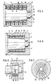
- the illustrated high-current docking connector device comprises a socket part 1 and a pin part 2 engaging in it.
- a plurality of contact ring groups 3 are arranged axially one behind the other in the socket part 1.
- each contact ring group 3 comprises a slotted socket outer contact ring 4 with a contact surface 5 which rests elastically on the inner surface of the socket part 1 and a slotted socket inner contact ring 6 with an elastically abutting plug part 2 in the inserted state Contact surface 7.
- the socket inner contact ring 6 and the socket outer contact ring 4 of each contact ring group 3 are provided with matched taper contact surfaces 8 and 9, respectively.
- all illustrated embodiments in the socket part 1 have a socket shoulder 10 which limits the axial displaceability of the contact ring groups 3 and is formed by a diameter reduction.
- at least one snap ring 11 is provided, which is fixed in an annular groove 12 of the socket part 1.
- the plug pin part 2 of all embodiments comprises a cylindrical guide area 15 projecting beyond its contact surface area 14. This area symbolizes the installation space for drip-free water plug connections.
- the socket outer contact ring 4 is normally designed as a solid rotating part which is provided with a slot 17 for the elastic contact on the inner surface of the socket part 1 is.
- FIGS. 1, 2 and 3 show the manner in which the plug pin part 2 comes into contact with the socket part 1 when it is introduced into the intermediate contact rings 4, 6 of each contact ring group 3.
- the inner bushing rings 6 are initially in a state in which they are lifted from the outer bushing ring 4.
- the plug pin part 2 is inserted into the female inner contact ring 6, it is carried along until the outer end face 18 stops on the mating surface 19 of the female outer contact ring 4 facing it and then expanded until the game exaggerated in FIGS. 1, 2 and 3 between the cone contact surfaces 8 and 9 is practically canceled.
- the current can then from the connector part 2 Flow over the socket inner contact ring 6 and the end face 18 and counter surface 19 to the socket outer contact ring 4 and thus to the socket part 1, if necessary additionally via the cone contact surfaces 8 and 9 to the adjacent socket outer contact ring 4 and from there to the socket part 1.
- the number of current transition areas multiplies according to the number of the provided contact ring groups 3.
- each contact ring group 3 thus consists of a socket inner contact ring 6 and two socket outer contact rings 4.
- the individual contact ring groups 3 are fixed in their position within the socket part 1 by snap rings 20 which engage in corresponding ring grooves in the socket part 1.
- the contact rings of each contact ring group 3 are held by two corrugated spring washers 21 which are supported on the adjacent snap rings 20 or 11 or the socket shoulder 10 in mutual contact and thus in contact with the outer surface of the plug pin part 2 or the inner surface of the socket part 1.
- 4 shows that each socket inner contact ring 6 has two cone contact surfaces 8, on which the corresponding cone contact surfaces 9 of the socket outer contact rings 4 come to rest.
- each female inner contact ring 6 is assigned a spring ring 22 which acts radially towards the surface of the male pin part 2.
- the spring ring 22 rests on the outside of the socket inner contact ring 6.
- FIG. 9 shows an embodiment in which the female inner contact ring 6 has an axially parallel groove 23 that is open to the side for receiving the spring ring 22.
- a modified embodiment is illustrated, in which the female outer contact ring 4 of the contact ring groups 3 is each formed from a sheet metal strip 24, as is illustrated in greater detail in FIGS. 17 and 18, by punching out tongues 25 directed towards the edge of the strip.
- These tongues 25 form the cone contact surface 9, on which the socket inner contact ring 6 with its corresponding cone contact surface 8 resiliently comes into contact.
- the tongues 25 are alternately punched out and angled toward the two sides of the strip edge.
- the socket inner contact ring 6 accordingly comprises two cone contact surfaces 8.8 ', on which the angled tongues 25 are supported resiliently.
- both the socket part 1 and the plug pin part 2 each have a central bore 26, through which cooling water for dissipating the heat generated in the area of welding guns or the like can be conducted after the plug connection has been made. Sealing is ensured by sealing means provided in the guide area 15, known per se and not shown in the drawing.
Landscapes
- Engineering & Computer Science (AREA)
- Physics & Mathematics (AREA)
- Plasma & Fusion (AREA)
- Mechanical Engineering (AREA)
- Connector Housings Or Holding Contact Members (AREA)
- Coupling Device And Connection With Printed Circuit (AREA)
- Earth Drilling (AREA)
- Manufacturing Of Electrical Connectors (AREA)
Applications Claiming Priority (2)
| Application Number | Priority Date | Filing Date | Title |
|---|---|---|---|
| DE3918950 | 1989-06-09 | ||
| DE3918950A DE3918950A1 (de) | 1989-06-09 | 1989-06-09 | Wassergekuehlte hochstrom-andocksteckverbindungsvorrichtung |
Publications (2)
| Publication Number | Publication Date |
|---|---|
| EP0401640A1 true EP0401640A1 (fr) | 1990-12-12 |
| EP0401640B1 EP0401640B1 (fr) | 1993-10-27 |
Family
ID=6382473
Family Applications (1)
| Application Number | Title | Priority Date | Filing Date |
|---|---|---|---|
| EP90110101A Expired - Lifetime EP0401640B1 (fr) | 1989-06-09 | 1990-05-28 | Dispositif de connection électrique refroidi par eau, pour courant fort |
Country Status (7)
| Country | Link |
|---|---|
| US (1) | US5080593A (fr) |
| EP (1) | EP0401640B1 (fr) |
| JP (1) | JPH0325871A (fr) |
| KR (1) | KR910002048A (fr) |
| AT (1) | ATE96580T1 (fr) |
| DE (2) | DE3918950A1 (fr) |
| DK (1) | DK0401640T3 (fr) |
Cited By (1)
| Publication number | Priority date | Publication date | Assignee | Title |
|---|---|---|---|---|
| EP2104183A1 (fr) | 2008-03-18 | 2009-09-23 | ABB Schweiz AG | Dispositif de raccordement électrique et raccord |
Families Citing this family (9)
| Publication number | Priority date | Publication date | Assignee | Title |
|---|---|---|---|---|
| DE9401605U1 (de) * | 1994-01-08 | 1994-03-31 | Elektron - Bremen Fabrik für Elektrotechnik GmbH, 28197 Bremen | Steckverbindung |
| US5591039A (en) * | 1995-06-01 | 1997-01-07 | Elcon Products International | Socket contact with arc arresting member |
| WO2012051510A2 (fr) | 2010-10-14 | 2012-04-19 | Gregory Thomas Mark | Connexion électrique à refroidissement actif |
| US9543677B1 (en) * | 2015-07-29 | 2017-01-10 | Stein Industries Inc. | Quick connector |
| PT3402023T (pt) * | 2017-05-08 | 2023-06-05 | Nkt Hv Cables Ab | Cabeça de extracção para um cabo de alta tensão |
| EP3963675A4 (fr) * | 2019-05-03 | 2023-05-10 | Rampart Products LLC | Connecteur rotatif multi-conducteur |
| US11296466B2 (en) | 2020-07-30 | 2022-04-05 | The Esab Group Inc. | Coradial connector |
| US12080975B2 (en) | 2021-03-29 | 2024-09-03 | Tbi Industries Gmbh | Multi-diameter power pin and receiving socket |
| CN113612049B (zh) * | 2021-07-29 | 2024-09-17 | 中航光电科技股份有限公司 | 宝塔式接触件 |
Citations (3)
| Publication number | Priority date | Publication date | Assignee | Title |
|---|---|---|---|---|
| DE2318690B2 (de) * | 1973-04-13 | 1978-04-27 | Leybold-Heraeus Gmbh & Co Kg, 5000 Koeln | Drehbare Hochstromverbindung |
| US4714441A (en) * | 1987-01-29 | 1987-12-22 | Amp Incorporated | Electrical socket |
| US4772233A (en) * | 1983-09-19 | 1988-09-20 | Trilogy Computer Development Partners, Ltd. | Low resistance connector |
Family Cites Families (8)
| Publication number | Priority date | Publication date | Assignee | Title |
|---|---|---|---|---|
| US2533343A (en) * | 1944-11-03 | 1950-12-12 | Bac Fernand Georges | Electric connecting device |
| US2879490A (en) * | 1954-07-21 | 1959-03-24 | Taylor Winfield Corp | Rotary current transfer device |
| US3208025A (en) * | 1962-07-10 | 1965-09-21 | Taylor Winfield Corp | Rotary current transfer device |
| FR2285732A1 (fr) * | 1974-09-23 | 1976-04-16 | France Etat | Dispositif isobare a contacts electriques tournants |
| SU951502A1 (ru) * | 1980-04-10 | 1982-08-15 | Ордена Ленина И Ордена Трудового Красного Знамени Предприятие П/Я Г-4725 | Электрический соединитель |
| US4405196A (en) * | 1981-01-12 | 1983-09-20 | Fulton Robert W | Electrical connector for high fidelity audio equipment |
| US4507008A (en) * | 1983-05-13 | 1985-03-26 | At&T Bell Laboratories | Stranded cable termination arrangement |
| DE3605076A1 (de) * | 1986-02-18 | 1987-08-20 | Manfred Frankauer | Elektrischer steckkontakt |
-
1989
- 1989-06-09 DE DE3918950A patent/DE3918950A1/de not_active Withdrawn
-
1990
- 1990-05-28 AT AT90110101T patent/ATE96580T1/de not_active IP Right Cessation
- 1990-05-28 EP EP90110101A patent/EP0401640B1/fr not_active Expired - Lifetime
- 1990-05-28 DK DK90110101.4T patent/DK0401640T3/da active
- 1990-05-28 DE DE90110101T patent/DE59003196D1/de not_active Expired - Fee Related
- 1990-06-04 US US07/532,580 patent/US5080593A/en not_active Expired - Fee Related
- 1990-06-07 JP JP2149724A patent/JPH0325871A/ja active Pending
- 1990-06-07 KR KR1019900008366A patent/KR910002048A/ko not_active Abandoned
Patent Citations (3)
| Publication number | Priority date | Publication date | Assignee | Title |
|---|---|---|---|---|
| DE2318690B2 (de) * | 1973-04-13 | 1978-04-27 | Leybold-Heraeus Gmbh & Co Kg, 5000 Koeln | Drehbare Hochstromverbindung |
| US4772233A (en) * | 1983-09-19 | 1988-09-20 | Trilogy Computer Development Partners, Ltd. | Low resistance connector |
| US4714441A (en) * | 1987-01-29 | 1987-12-22 | Amp Incorporated | Electrical socket |
Cited By (2)
| Publication number | Priority date | Publication date | Assignee | Title |
|---|---|---|---|---|
| EP2104183A1 (fr) | 2008-03-18 | 2009-09-23 | ABB Schweiz AG | Dispositif de raccordement électrique et raccord |
| US7641506B2 (en) | 2008-03-18 | 2010-01-05 | Abb Schweiz Ag | Electrical connection device and connector |
Also Published As
| Publication number | Publication date |
|---|---|
| KR910002048A (ko) | 1991-01-31 |
| EP0401640B1 (fr) | 1993-10-27 |
| ATE96580T1 (de) | 1993-11-15 |
| DK0401640T3 (da) | 1993-12-06 |
| US5080593A (en) | 1992-01-14 |
| DE59003196D1 (de) | 1993-12-02 |
| JPH0325871A (ja) | 1991-02-04 |
| DE3918950A1 (de) | 1990-12-13 |
Similar Documents
| Publication | Publication Date | Title |
|---|---|---|
| EP0663107B1 (fr) | Paire de connecteurs a fiches | |
| DE69222400T2 (de) | Universelles Werkzeug zum Lösen von Schnellkupplungen | |
| DE3026386A1 (de) | Steckverbindung mit visueller, tastbarer und hoerbarer anzeige | |
| DE1490840B2 (de) | Elektrische steckkupplung zur verbindung koaxialer leitungen | |
| DE2611558A1 (de) | Kupplungsdrucklager | |
| DE102019114257B4 (de) | Steckverbinder mit Verriegelungssystem | |
| DE102008009350A1 (de) | Steckverbindung mit einer Kodiervorrichtung und Verfahren zur Montage der Kodiervorrichtung an der Steckverbindung | |
| EP0915534A2 (fr) | Connecteur électrique à verrouillage rapide | |
| EP0401640B1 (fr) | Dispositif de connection électrique refroidi par eau, pour courant fort | |
| CH624245A5 (en) | Device for the secure locking and unlocking of a plug connector for electrical cables or optical-fibre cables | |
| EP4136714B1 (fr) | Connecteur à fiche ronde comprenant un raccord de blindage | |
| EP3742561B1 (fr) | Connecteur électrique enfichable | |
| EP1109277B1 (fr) | Elément d'accouplement de deux appareils électriques montés côte-à-côte, et méthode d'accouplement d'appareillages électriques | |
| EP3884197B1 (fr) | Accouplement | |
| DE102019130491B3 (de) | Elektrisches Steckverbindersystem mit Sperrelement | |
| DE202004013708U1 (de) | Verbindungselement zur Herstellung einer Verbindung zwischen Installationsschaltgeräten | |
| DE102017125915B4 (de) | Verriegelung für Steckverbinder | |
| DE20000160U1 (de) | Elektrisches Steckverbindungsteil | |
| DE10335514A1 (de) | Rohrverbindung | |
| DE3930210C2 (fr) | ||
| DE102018107886B4 (de) | Steckverbindersystem mit einem bistabilen Element | |
| DE2616621A1 (de) | Steckverbinder | |
| DE102011052387A1 (de) | Federdruckstück zur Herstellung eines elektrischen Federkontaktelements und elektrischer Steckverbinder | |
| EP2249438A2 (fr) | Prise pour un connecteur à fiches multipolaire | |
| DE102022004927A1 (de) | Vorrichtung zum Herstellen einer elektrischen Verbindung |
Legal Events
| Date | Code | Title | Description |
|---|---|---|---|
| PUAI | Public reference made under article 153(3) epc to a published international application that has entered the european phase |
Free format text: ORIGINAL CODE: 0009012 |
|
| AK | Designated contracting states |
Kind code of ref document: A1 Designated state(s): AT BE CH DE DK FR GB IT LI LU NL SE |
|
| 17P | Request for examination filed |
Effective date: 19901212 |
|
| 17Q | First examination report despatched |
Effective date: 19930318 |
|
| GRAA | (expected) grant |
Free format text: ORIGINAL CODE: 0009210 |
|
| AK | Designated contracting states |
Kind code of ref document: B1 Designated state(s): AT BE CH DE DK FR GB IT LI LU NL SE |
|
| REF | Corresponds to: |
Ref document number: 96580 Country of ref document: AT Date of ref document: 19931115 Kind code of ref document: T |
|
| REF | Corresponds to: |
Ref document number: 59003196 Country of ref document: DE Date of ref document: 19931202 |
|
| REG | Reference to a national code |
Ref country code: DK Ref legal event code: T3 |
|
| ITF | It: translation for a ep patent filed | ||
| ET | Fr: translation filed | ||
| GBT | Gb: translation of ep patent filed (gb section 77(6)(a)/1977) |
Effective date: 19931119 |
|
| PGFP | Annual fee paid to national office [announced via postgrant information from national office to epo] |
Ref country code: BE Payment date: 19940505 Year of fee payment: 5 |
|
| PGFP | Annual fee paid to national office [announced via postgrant information from national office to epo] |
Ref country code: GB Payment date: 19940519 Year of fee payment: 5 |
|
| PGFP | Annual fee paid to national office [announced via postgrant information from national office to epo] |
Ref country code: SE Payment date: 19940526 Year of fee payment: 5 Ref country code: FR Payment date: 19940526 Year of fee payment: 5 |
|
| PGFP | Annual fee paid to national office [announced via postgrant information from national office to epo] |
Ref country code: AT Payment date: 19940530 Year of fee payment: 5 |
|
| PGFP | Annual fee paid to national office [announced via postgrant information from national office to epo] |
Ref country code: NL Payment date: 19940531 Year of fee payment: 5 Ref country code: LU Payment date: 19940531 Year of fee payment: 5 |
|
| PGFP | Annual fee paid to national office [announced via postgrant information from national office to epo] |
Ref country code: DK Payment date: 19940630 Year of fee payment: 5 |
|
| EPTA | Lu: last paid annual fee | ||
| PLBE | No opposition filed within time limit |
Free format text: ORIGINAL CODE: 0009261 |
|
| STAA | Information on the status of an ep patent application or granted ep patent |
Free format text: STATUS: NO OPPOSITION FILED WITHIN TIME LIMIT |
|
| 26N | No opposition filed | ||
| EAL | Se: european patent in force in sweden |
Ref document number: 90110101.4 |
|
| PG25 | Lapsed in a contracting state [announced via postgrant information from national office to epo] |
Ref country code: LU Free format text: LAPSE BECAUSE OF NON-PAYMENT OF DUE FEES Effective date: 19950528 Ref country code: GB Effective date: 19950528 Ref country code: DK Effective date: 19950528 Ref country code: AT Effective date: 19950528 |
|
| REG | Reference to a national code |
Ref country code: DK Ref legal event code: EBP |
|
| PG25 | Lapsed in a contracting state [announced via postgrant information from national office to epo] |
Ref country code: SE Effective date: 19950529 |
|
| PGFP | Annual fee paid to national office [announced via postgrant information from national office to epo] |
Ref country code: CH Payment date: 19950530 Year of fee payment: 6 |
|
| PG25 | Lapsed in a contracting state [announced via postgrant information from national office to epo] |
Ref country code: BE Effective date: 19950531 |
|
| PGFP | Annual fee paid to national office [announced via postgrant information from national office to epo] |
Ref country code: DE Payment date: 19950731 Year of fee payment: 6 |
|
| BERE | Be: lapsed |
Owner name: OTTO DUNKEL G.M.B.H. FABRIK FUR ELEKTROTECHNISCHE Effective date: 19950531 |
|
| PG25 | Lapsed in a contracting state [announced via postgrant information from national office to epo] |
Ref country code: NL Effective date: 19951201 |
|
| GBPC | Gb: european patent ceased through non-payment of renewal fee |
Effective date: 19950528 |
|
| NLV4 | Nl: lapsed or anulled due to non-payment of the annual fee |
Effective date: 19951201 |
|
| EUG | Se: european patent has lapsed |
Ref document number: 90110101.4 |
|
| PG25 | Lapsed in a contracting state [announced via postgrant information from national office to epo] |
Ref country code: FR Effective date: 19960229 |
|
| REG | Reference to a national code |
Ref country code: FR Ref legal event code: ST |
|
| REG | Reference to a national code |
Ref country code: FR Ref legal event code: ST |
|
| PG25 | Lapsed in a contracting state [announced via postgrant information from national office to epo] |
Ref country code: LI Effective date: 19960531 Ref country code: CH Effective date: 19960531 |
|
| REG | Reference to a national code |
Ref country code: CH Ref legal event code: PL |
|
| PG25 | Lapsed in a contracting state [announced via postgrant information from national office to epo] |
Ref country code: DE Effective date: 19970201 |
|
| PG25 | Lapsed in a contracting state [announced via postgrant information from national office to epo] |
Ref country code: IT Free format text: LAPSE BECAUSE OF NON-PAYMENT OF DUE FEES;WARNING: LAPSES OF ITALIAN PATENTS WITH EFFECTIVE DATE BEFORE 2007 MAY HAVE OCCURRED AT ANY TIME BEFORE 2007. THE CORRECT EFFECTIVE DATE MAY BE DIFFERENT FROM THE ONE RECORDED. Effective date: 20050528 |