EP0401659A1 - Fixation d'une bavette de garde-boue - Google Patents
Fixation d'une bavette de garde-boue Download PDFInfo
- Publication number
- EP0401659A1 EP0401659A1 EP90110246A EP90110246A EP0401659A1 EP 0401659 A1 EP0401659 A1 EP 0401659A1 EP 90110246 A EP90110246 A EP 90110246A EP 90110246 A EP90110246 A EP 90110246A EP 0401659 A1 EP0401659 A1 EP 0401659A1
- Authority
- EP
- European Patent Office
- Prior art keywords
- clamping
- mud flap
- screws
- projections
- clamp
- Prior art date
- Legal status (The legal status is an assumption and is not a legal conclusion. Google has not performed a legal analysis and makes no representation as to the accuracy of the status listed.)
- Granted
Links
- 230000006978 adaptation Effects 0.000 claims abstract description 15
- 238000013459 approach Methods 0.000 claims description 11
- 230000003014 reinforcing effect Effects 0.000 claims description 6
- 230000001154 acute effect Effects 0.000 claims description 3
- 230000002787 reinforcement Effects 0.000 description 4
- 239000000463 material Substances 0.000 description 2
- 239000011248 coating agent Substances 0.000 description 1
- 238000000576 coating method Methods 0.000 description 1
- 230000000694 effects Effects 0.000 description 1
- 210000003608 fece Anatomy 0.000 description 1
- 238000009413 insulation Methods 0.000 description 1
- 239000012774 insulation material Substances 0.000 description 1
- 238000000034 method Methods 0.000 description 1
Images


Classifications
-
- B—PERFORMING OPERATIONS; TRANSPORTING
- B62—LAND VEHICLES FOR TRAVELLING OTHERWISE THAN ON RAILS
- B62D—MOTOR VEHICLES; TRAILERS
- B62D25/00—Superstructure or monocoque structure sub-units; Parts or details thereof not otherwise provided for
- B62D25/08—Front or rear portions
- B62D25/16—Mud-guards or wings; Wheel cover panels
- B62D25/18—Parts or details thereof, e.g. mudguard flaps
Definitions
- the invention relates to a mud flap attachment for releasably connecting the fastening area of a mud flap formed by the edge area of the adaptation approach and coming to rest on the fender rebate of the motor vehicle, which has a rag main body, in the extension of which the adaptation approach lies, with at least one clamp for clamping the mud flap on Fender rebate, which has a clamping part which is connected to the other clamp part by means of two screws arranged at a distance from one another in the direction of the longitudinal extent of the fastening region, at least the clamp part having on its side forming the clamping opening in the direction of the clamp part beveled corner region.
- a clamp is used for the clamping attachment of the mud flap which can be used universally and which has a main flap body and an adaptation shoulder lying essentially in the same plane as this used, which consists of an elongated clamp part and a correspondingly shaped elongated clamp part, which are connected to one another by two spaced screws and whose continuous opening-forming sides, which run parallel to the connecting line of the two screws, are bent at their outer corner regions in order to bring about a firm engagement of the clamping part with the inside of the fender rebate and of the clamp part with the forward-facing surface of the fastening area of the mud flap in the clamped state.
- a strainer attachment of the type mentioned is designed according to the invention in such a way that the side of the clamping part forming the clamping opening has a central recess open to the side facing away from the screws, the sides of which are formed by two clamping projections, that both corner regions of the free ends of the clamping projections are kinked in the direction of the clamp part and that the distance from the associated screw to the free end of the clamping projection which is higher in the assembled state is smaller than the corresponding distance from the other clamping projection.
- the use of a single clamp is thus made possible by at least its clamp part having four corner regions angled in the direction of the clamp part, which in the assembled state engage in clawing engagement with the inside of the fender rebate or with insulation or insulation material provided on this inside come, so that, compared to the previously known clamp with two screws, a significantly higher clamping effect is achieved, through which a secure connection of mud flaps and fender rebate is ensured.
- the screws of the clamp are preferably each arranged on the longitudinal central axis of the associated clamping projection, so that there is a symmetrical position with respect to the corner regions of the clamping part which come into engagement with the rear of the fender rebate.
- the outer edge of the free end, at least of the clamping projection lying lower in the assembled state can enclose an acute angle with the connecting line of the two screws, the apex of which in the assembled state is higher than the higher of the two Screws.
- the outer edges of the free ends of both clamping projections preferably lie on a common straight line.
- threaded bores can be provided in the clamping part for receiving the screws, so that the screws are arranged with their heads on the outside of the clamp part and are easily accessible from this for the assembler Liche side can be tightened to bring the clip in its closed state.
- At least one bend forming a support is provided for engagement with the clamping part.
- the clamp part is formed by a reinforcing plate which, in the assembled state, extends on the surface of the fastening region facing away from the fender rebate and has lugs for the engagement of the screws.
- This known reinforcement plate (DE-PS 23 42 365) is also used as a clamp part. Since the reinforcement plate is normally riveted to the mud flap, the clamp is held in place after the fender rebate has been positioned accordingly and the mud flap has been aligned and the mud flap has been aligned by holding the mud flap in place, and it is then only necessary to tighten the screws of the clamp without that there is a risk that the clamp will shift during this assembly process with respect to the mud flap and / or with respect to the fender rebate.
- clamp part in accordance with the clamp part and thus to provide it with two clamp projections corresponding to the clamp projections, which have bent corner areas in order to achieve a secure engagement with the material of the mud flap, whereby the clamp projections can usually have the same length.
- passenger cars in the area of the wheel arches usually have a so-called fender rebate 2, which is formed by angling the body 1 in the area of the wheel arches and which in many cases serves to fasten dirt traps, as is described in DE-PS 23 42 365 and also described in DE-PS 29 05 753.
- These dirt traps as indicated by dash-dotted lines in FIG. 2, have a dirt trap flap 3 with an essentially flat main body 4 and an adjoining extension 5 which adjoins this upwards and which has an inner edge area for contact with the droppings wing rebate 2 coming fastening area, wherein the course of the inner edge of the adaptation approach 5 should match as closely as possible with the course of the free edge of the fender rebate 2.
- a bendable reinforcing plate 6 is provided on the surface of the mud flap 3 facing the wheel in the assembled state, i.e. the surface facing away from the fender rebate 2, in the area of the inner edge of the adaptation projection 5, which is provided by rivets 7 in the area of the Upper edge of the main flap body 4 is attached to the main flap body 4.
- the form and task of such a reinforcement plate are described in DE-PS 23 42 365.
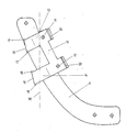
- two lugs 21, 22 are formed at a distance from each other on the edge located on the inner edge of the adaptation projection 5, which lie essentially in the plane of the reinforcing plate 6 and form bends 23 and 24 at their free ends.
- the lugs 21 and 22 there are through holes through which screws 11, 12 are inserted, which are used for connection to the clamping part 10.
- the clamping part 10 has two threaded bores, for example spaced from 50 to 58 mm, through which the screws 11 and 12 extend. It has two essentially parallel clamping projections 13, 14, which have between them a width of 30 mm to 35 mm, for example Form central recess, which is open on the side facing away from the screws 11 and 12. On the side of the clamping part 10 closer to the screws 11 and 12 there are bends 19 and 20 which correspond to the bends 23 and 24 of the clip projections 21 and 22 and which are arranged adjacent to form a support.
- the free corner areas of the clamping projections 13 and 14 are kinked in the direction of the reinforcement plate 6 and the kinks 17 and 18 thus formed come into engagement in the assembled state with the rear side of the fender rebate 12 or with coating material applied to this rear side (FIG. 2) .
- the length of the clamping projection 13 of the screw 11, which is arranged centrally with respect to this clamping projection 13, is shorter than the corresponding length of the clamping projection 14.
- the lower corner 17 or 18 of the clamping projection 13 or 14 in FIG. 3 has a greater distance from the associated screw 11 or 12 than the upper corner 17 or 18 in FIG. 3.
- This unequal design of the two clamping projections 13 and 14 means that the dirt trap can also be attached to a relatively steeply extending fender rebate, as is indicated schematically by the broken line 30 in FIG Corners 18 of the clamping projection 14 with the rear side of the fender rebate 2 possible. If the clamping projection 14 had the same length as the clamping projection 13, then in the case shown, at least least with the lower bend 18 of the clamping projection 14 no longer reach engagement with the fender rebate 2, and in many cases the lower clamping projection 14 could not come into contact with the fender rebate at all. However, this leads to an insufficient fastening of the dirt trap.
- the clamp part 110 instead of the clamp projections formed on a reinforcing plate, the clamp part 110 cooperates with a clamp part 106 which has clamp projections 121 and 122 corresponding to the clamp projections 21 and 22, this being part of the clamp part 106 are and form a central cutout between them, which is open on the same side as the central recess between the clamping projections 113 and 114.
- These clamping projections 121 and 122 are bent at their free corners in the direction of the clamping part 110 and thus form engagement areas 137 and 138 for the Engagement with the front surface of the mud flap to be attached to the fender rebate.
Landscapes
- Engineering & Computer Science (AREA)
- Chemical & Material Sciences (AREA)
- Combustion & Propulsion (AREA)
- Transportation (AREA)
- Mechanical Engineering (AREA)
- Body Structure For Vehicles (AREA)
Applications Claiming Priority (2)
| Application Number | Priority Date | Filing Date | Title |
|---|---|---|---|
| DE3918802A DE3918802A1 (de) | 1989-06-06 | 1989-06-06 | Schmutzfaengerbefestigung |
| DE3918802 | 1989-06-06 |
Publications (2)
| Publication Number | Publication Date |
|---|---|
| EP0401659A1 true EP0401659A1 (fr) | 1990-12-12 |
| EP0401659B1 EP0401659B1 (fr) | 1993-07-21 |
Family
ID=6382388
Family Applications (1)
| Application Number | Title | Priority Date | Filing Date |
|---|---|---|---|
| EP90110246A Expired - Lifetime EP0401659B1 (fr) | 1989-06-06 | 1990-05-30 | Fixation d'une bavette de garde-boue |
Country Status (5)
| Country | Link |
|---|---|
| US (1) | US5048868A (fr) |
| EP (1) | EP0401659B1 (fr) |
| DE (2) | DE3918802A1 (fr) |
| PT (1) | PT94256B (fr) |
| ZA (1) | ZA904293B (fr) |
Cited By (2)
| Publication number | Priority date | Publication date | Assignee | Title |
|---|---|---|---|---|
| EP0680867A1 (fr) * | 1994-05-04 | 1995-11-08 | WEGU Gummi- und Kunststoffwerke Walter Dräbing KG | Garde-boue pour camions |
| US11345411B2 (en) * | 2020-04-24 | 2022-05-31 | Mfc Technology Corp. | Toolless mud flap mounting system and method |
Families Citing this family (37)
| Publication number | Priority date | Publication date | Assignee | Title |
|---|---|---|---|---|
| US6186527B1 (en) * | 1998-03-06 | 2001-02-13 | Garry Monhollen | Mud flap assembly |
| DE19830668C1 (de) * | 1998-07-09 | 2000-04-06 | Daimler Chrysler Ag | Anordnung zum Zusammenfügen von flächigen Bauteilen, insbesondere Außenhautteilen eines Kraftfahrzeuges |
| US6193278B1 (en) | 1999-04-13 | 2001-02-27 | Douglas K. Ward | Splash guard and method of making |
| US7114749B2 (en) * | 2003-01-17 | 2006-10-03 | Ward Douglas K | Splash guard kit and assembly |
| DE10343381B4 (de) * | 2003-09-19 | 2005-12-08 | Dr.Ing.H.C. F. Porsche Ag | Lösbare Verbindung zwischen zwei angrenzenden Bauteilen, insbesondere Außenhautteilen einer Fahrzeugkarosserie |
| US6994376B1 (en) * | 2003-11-03 | 2006-02-07 | Deering Anthony G | Quick release mud flap apparatus |
| US7537243B1 (en) | 2004-05-13 | 2009-05-26 | William Dennis Perry | Mud flap retrofit kit and method of use |
| US20050275212A1 (en) * | 2004-06-12 | 2005-12-15 | Angelaitis Robert J | Flexible truck fender flare with integral front and rear mud flaps |
| US7578526B2 (en) * | 2004-11-30 | 2009-08-25 | Jason Jaeger | releasable pliant non-marring mud flap |
| FR2878810B1 (fr) * | 2004-12-03 | 2007-03-16 | Peugeot Citroen Automobiles Sa | Bavette de vehicule automobile et dispositif de fixation |
| JP4676281B2 (ja) * | 2005-08-25 | 2011-04-27 | 川崎重工業株式会社 | 車両のフラップ |
| US7578527B2 (en) * | 2006-09-22 | 2009-08-25 | David F. MacNeil | Vehicle mud flap with fender fold clamp |
| US7766356B2 (en) * | 2007-09-17 | 2010-08-03 | Macneil Ip Llc | Vehicle mud flap with fastening tab |
| US7717467B2 (en) * | 2006-10-30 | 2010-05-18 | David F. MacNeil | Vehicle mud flap with sliding fender fold clamp |
| US8118329B2 (en) * | 2007-12-27 | 2012-02-21 | Bushwacker, Inc. | Fender flares and vehicles with fender flares |
| US7914046B2 (en) * | 2008-03-19 | 2011-03-29 | Macneil Ip Llc | Vehicle mud flap with wheel liner attachment tab |
| US8651554B1 (en) | 2010-02-26 | 2014-02-18 | Lund, Inc. | Vehicle shield |
| US20110304129A1 (en) * | 2010-06-15 | 2011-12-15 | Charles Owens | Combination Wheel Skirt Cover and Mud Guard |
| US8651528B2 (en) * | 2011-06-17 | 2014-02-18 | Nissan North America, Inc. | Vehicle splash guard |
| US9022428B2 (en) * | 2011-11-02 | 2015-05-05 | Nissan North America, Inc. | Vehicle splash guard |
| US8991868B2 (en) * | 2011-12-02 | 2015-03-31 | Powerflow, Inc. | Splash guard attachment clip assembly |
| US9371094B1 (en) | 2014-12-15 | 2016-06-21 | Ford Motor Company Brasil Ltda | Plastic panel attachment joint for fascia to fender execution |
| US20160362143A1 (en) * | 2015-06-12 | 2016-12-15 | GM Global Technology Operations LLC | Splash guard assembly and product |
| US9878600B2 (en) | 2015-10-30 | 2018-01-30 | Lund, Inc. | Vehicle hood shield and bracket system |
| US10183703B2 (en) | 2017-06-09 | 2019-01-22 | Jaeger Brothers Automotive Accessories, Inc. | Conformable mud flap |
| USD906200S1 (en) | 2018-10-26 | 2020-12-29 | Bushwacker, Inc. | Fender flare |
| USD906202S1 (en) | 2018-10-26 | 2020-12-29 | Bushwacker, Inc. | Fender flare |
| USD887338S1 (en) * | 2018-10-26 | 2020-06-16 | Omix-Ada, Inc. | Support bracket |
| US11225213B2 (en) | 2018-10-26 | 2022-01-18 | Lund, Inc. | Vehicle body shield |
| US11220161B2 (en) | 2018-10-26 | 2022-01-11 | Lund, Inc. | Window deflector assembly with mounting clips |
| USD898640S1 (en) | 2018-10-26 | 2020-10-13 | Bushwacker, Inc. | Vehicle fender flare |
| CA187177S (en) | 2018-10-26 | 2020-10-22 | Bushwacker Inc | Fender flare |
| US10994787B2 (en) * | 2019-09-26 | 2021-05-04 | Nissan North America, Inc. | Vehicle splash guard |
| USD1021721S1 (en) * | 2022-03-15 | 2024-04-09 | Darrell Thomas | Mud flap accessory |
| USD1037958S1 (en) * | 2022-12-26 | 2024-08-06 | Jinjiang Temodou Technology Co., Ltd. | Mud flap kit |
| USD1099001S1 (en) * | 2023-02-16 | 2025-10-21 | Jaguar Land Rover Limited | Mudflap mount |
| USD1095365S1 (en) * | 2023-10-11 | 2025-09-30 | Landon Cole McMath | Vehicle mud flap |
Citations (4)
| Publication number | Priority date | Publication date | Assignee | Title |
|---|---|---|---|---|
| DE2352472B2 (de) * | 1972-12-21 | 1978-02-02 | Arenhold, Knut, 7640 Kehl | Schmutzfaenger |
| DE2342365C3 (de) * | 1972-12-21 | 1978-07-27 | Arenhold, Knut, 2000 Hamburg | Schmutzfänger |
| DE2851748A1 (de) * | 1978-11-30 | 1980-06-04 | Arenhold K | Universal-schmutzfaenger fuer kraftfahrzeuge |
| DE2905753C2 (fr) * | 1979-02-15 | 1988-09-22 | Knut 2000 Hamburg De Arenhold |
Family Cites Families (4)
| Publication number | Priority date | Publication date | Assignee | Title |
|---|---|---|---|---|
| JPS5513182Y2 (fr) * | 1976-06-11 | 1980-03-25 | ||
| US4323262A (en) * | 1978-11-30 | 1982-04-06 | Arenhold K | Universal mudguard flap and clamp for motor vehicles |
| DE3315341A1 (de) * | 1983-04-28 | 1984-10-31 | Knut 2000 Hamburg Arenhold | Vorrichtung zur befestigung eines schmutzfaengers am kotfluegelfalz eines kraftfahrzeugs |
| DE8329615U1 (de) * | 1983-10-11 | 1985-03-21 | Arenhold, Knut, 2000 Hamburg | Schmutzfaenger |
-
1989
- 1989-06-06 DE DE3918802A patent/DE3918802A1/de not_active Ceased
-
1990
- 1990-05-30 DE DE9090110246T patent/DE59002012D1/de not_active Expired - Fee Related
- 1990-05-30 EP EP90110246A patent/EP0401659B1/fr not_active Expired - Lifetime
- 1990-06-04 PT PT94256A patent/PT94256B/pt not_active IP Right Cessation
- 1990-06-05 ZA ZA904293A patent/ZA904293B/xx unknown
- 1990-06-05 US US07/533,559 patent/US5048868A/en not_active Expired - Fee Related
Patent Citations (4)
| Publication number | Priority date | Publication date | Assignee | Title |
|---|---|---|---|---|
| DE2352472B2 (de) * | 1972-12-21 | 1978-02-02 | Arenhold, Knut, 7640 Kehl | Schmutzfaenger |
| DE2342365C3 (de) * | 1972-12-21 | 1978-07-27 | Arenhold, Knut, 2000 Hamburg | Schmutzfänger |
| DE2851748A1 (de) * | 1978-11-30 | 1980-06-04 | Arenhold K | Universal-schmutzfaenger fuer kraftfahrzeuge |
| DE2905753C2 (fr) * | 1979-02-15 | 1988-09-22 | Knut 2000 Hamburg De Arenhold |
Cited By (2)
| Publication number | Priority date | Publication date | Assignee | Title |
|---|---|---|---|---|
| EP0680867A1 (fr) * | 1994-05-04 | 1995-11-08 | WEGU Gummi- und Kunststoffwerke Walter Dräbing KG | Garde-boue pour camions |
| US11345411B2 (en) * | 2020-04-24 | 2022-05-31 | Mfc Technology Corp. | Toolless mud flap mounting system and method |
Also Published As
| Publication number | Publication date |
|---|---|
| DE59002012D1 (de) | 1993-08-26 |
| DE3918802A1 (de) | 1990-12-13 |
| EP0401659B1 (fr) | 1993-07-21 |
| ZA904293B (en) | 1991-03-27 |
| PT94256B (pt) | 1997-02-28 |
| US5048868A (en) | 1991-09-17 |
| PT94256A (pt) | 1992-01-31 |
Similar Documents
| Publication | Publication Date | Title |
|---|---|---|
| EP0401659B1 (fr) | Fixation d'une bavette de garde-boue | |
| DE3315341A1 (de) | Vorrichtung zur befestigung eines schmutzfaengers am kotfluegelfalz eines kraftfahrzeugs | |
| DE29519375U1 (de) | Kunststoff-Befestigungselement, insbesondere für eine Fahrzeugverkleidung | |
| DE60019677T2 (de) | Verstellbare Montageplatte | |
| DE4208493C2 (de) | Halterung für eine Isoliermatte | |
| DE2342365C3 (de) | Schmutzfänger | |
| EP0872408B1 (fr) | Agencement pour le tableau de bord d'un véhicule automobile | |
| DE69516575T2 (de) | Befestigungselement für Kabel, Rohre oder dergleichen | |
| DE8913456U1 (de) | Konsole für einen plattenförmigen Heizkörper | |
| DE112021002933T5 (de) | Montagestruktur für dachmontage-antenne | |
| DE19730269C2 (de) | Vorrichtung zum Befestigen eines ersten Teils mit einem zweiten Teil | |
| DE3729824A1 (de) | Befestigungswinkel aus metall | |
| DE4415648C1 (de) | Schmutzfänger für Kraftfahrzeuge | |
| DE3804996C2 (fr) | ||
| DE3779804T2 (de) | Autodachanordnung. | |
| DE102006059096B4 (de) | Baugruppe zur fahrzeugseitigen Befestigung eines Gurtschlosses | |
| DE9413049U1 (de) | Vorrichtung zum Befestigen einer Abdeckleiste für Nuten von Kraftwagen-Aufbauten | |
| DE2905753A1 (de) | Universal-schmutzfaenger fuer kraftfahrzeuge | |
| EP0584084B1 (fr) | Piece colee en metal leger et son procede de fabrication | |
| DE2851748A1 (de) | Universal-schmutzfaenger fuer kraftfahrzeuge | |
| EP0612902B1 (fr) | Dispositif d'actionnement intérieur pour portes de véhicules | |
| DE29806876U1 (de) | Rechteckiges Gehäuse zur Aufnahme elektrischer oder elektronischer Bauteile (IV) | |
| DE8329615U1 (de) | Schmutzfaenger | |
| DE9011077U1 (de) | Drehmomentstütze für das Antriebsaggregat eines Kraftfahrzeuges | |
| WO1990007448A1 (fr) | Dispositif de fixation d'accessoires de carrosserie sur l'aile et/ou d'autres parties d'un vehicule |
Legal Events
| Date | Code | Title | Description |
|---|---|---|---|
| PUAI | Public reference made under article 153(3) epc to a published international application that has entered the european phase |
Free format text: ORIGINAL CODE: 0009012 |
|
| AK | Designated contracting states |
Kind code of ref document: A1 Designated state(s): BE DE DK ES FR GB IT |
|
| 17P | Request for examination filed |
Effective date: 19901126 |
|
| 17Q | First examination report despatched |
Effective date: 19920916 |
|
| GRAA | (expected) grant |
Free format text: ORIGINAL CODE: 0009210 |
|
| AK | Designated contracting states |
Kind code of ref document: B1 Designated state(s): BE DE DK ES FR GB IT |
|
| PG25 | Lapsed in a contracting state [announced via postgrant information from national office to epo] |
Ref country code: IT Free format text: LAPSE BECAUSE OF FAILURE TO SUBMIT A TRANSLATION OF THE DESCRIPTION OR TO PAY THE FEE WITHIN THE PRE;WARNING: LAPSES OF ITALIAN PATENTS WITH EFFECTIVE DATE BEFORE 2007 MAY HAVE OCCURRED AT ANY TIME BEFORE 2007. THE CORRECT EFFECTIVE DATE MAY BE DIFFERENT FROM THE ONE RECORDED.SCRIBED TIME-LIMIT Effective date: 19930721 Ref country code: DK Effective date: 19930721 Ref country code: BE Effective date: 19930721 Ref country code: ES Free format text: THE PATENT HAS BEEN ANNULLED BY A DECISION OF A NATIONAL AUTHORITY Effective date: 19930721 |
|
| REF | Corresponds to: |
Ref document number: 59002012 Country of ref document: DE Date of ref document: 19930826 |
|
| ET | Fr: translation filed | ||
| GBT | Gb: translation of ep patent filed (gb section 77(6)(a)/1977) |
Effective date: 19931001 |
|
| PLBE | No opposition filed within time limit |
Free format text: ORIGINAL CODE: 0009261 |
|
| STAA | Information on the status of an ep patent application or granted ep patent |
Free format text: STATUS: NO OPPOSITION FILED WITHIN TIME LIMIT |
|
| 26N | No opposition filed | ||
| REG | Reference to a national code |
Ref country code: GB Ref legal event code: IF02 |
|
| PGFP | Annual fee paid to national office [announced via postgrant information from national office to epo] |
Ref country code: DE Payment date: 20030718 Year of fee payment: 14 |
|
| PG25 | Lapsed in a contracting state [announced via postgrant information from national office to epo] |
Ref country code: DE Free format text: LAPSE BECAUSE OF NON-PAYMENT OF DUE FEES Effective date: 20041201 |
|
| PGFP | Annual fee paid to national office [announced via postgrant information from national office to epo] |
Ref country code: FR Payment date: 20050617 Year of fee payment: 16 |
|
| PGFP | Annual fee paid to national office [announced via postgrant information from national office to epo] |
Ref country code: GB Payment date: 20051129 Year of fee payment: 16 |
|
| PG25 | Lapsed in a contracting state [announced via postgrant information from national office to epo] |
Ref country code: GB Free format text: LAPSE BECAUSE OF NON-PAYMENT OF DUE FEES Effective date: 20060530 |
|
| GBPC | Gb: european patent ceased through non-payment of renewal fee |
Effective date: 20060530 |
|
| REG | Reference to a national code |
Ref country code: FR Ref legal event code: ST Effective date: 20070131 |
|
| PG25 | Lapsed in a contracting state [announced via postgrant information from national office to epo] |
Ref country code: FR Free format text: LAPSE BECAUSE OF NON-PAYMENT OF DUE FEES Effective date: 20060531 |