EP0401698B1 - Fördervorrichtung für Gegenstände - Google Patents
Fördervorrichtung für Gegenstände Download PDFInfo
- Publication number
- EP0401698B1 EP0401698B1 EP90110459A EP90110459A EP0401698B1 EP 0401698 B1 EP0401698 B1 EP 0401698B1 EP 90110459 A EP90110459 A EP 90110459A EP 90110459 A EP90110459 A EP 90110459A EP 0401698 B1 EP0401698 B1 EP 0401698B1
- Authority
- EP
- European Patent Office
- Prior art keywords
- rotary conveyor
- conveyor
- respect
- sucker
- containers
- Prior art date
- Legal status (The legal status is an assumption and is not a legal conclusion. Google has not performed a legal analysis and makes no representation as to the accuracy of the status listed.)
- Expired - Lifetime
Links
Images


Classifications
-
- B—PERFORMING OPERATIONS; TRANSPORTING
- B65—CONVEYING; PACKING; STORING; HANDLING THIN OR FILAMENTARY MATERIAL
- B65G—TRANSPORT OR STORAGE DEVICES, e.g. CONVEYORS FOR LOADING OR TIPPING, SHOP CONVEYOR SYSTEMS OR PNEUMATIC TUBE CONVEYORS
- B65G47/00—Article or material-handling devices associated with conveyors; Methods employing such devices
- B65G47/74—Feeding, transfer, or discharging devices of particular kinds or types
- B65G47/84—Star-shaped wheels or devices having endless travelling belts or chains, the wheels or devices being equipped with article-engaging elements
- B65G47/846—Star-shaped wheels or wheels equipped with article-engaging elements
- B65G47/848—Star-shaped wheels or wheels equipped with article-engaging elements the article-engaging elements being suction or magnetic means
Definitions
- the present invention relates to an apparatus for conveying products.
- the present invention relates to an apparatus of the above mentioned type which is adapted to be used for example to convey containers in a filling machine.
- the containers are conveyed by rotary conveyors which are peripherally provided with a plurality of equidistant seats adapted to accommodate respective containers.
- the containers accommodated in said seats of filling machines of the conventional type are furthermore retained within said seats by fixed guides against which the containers slide while being conveyed.
- the object of the present invention is to provide an apparatus for conveying products in which it is possible to vary the dimensions of the treated products by means of simple adjustments, without replacing mechanical parts and by means of operations which require only a very short time to carry out.
- a further object of the present invention is to provide an apparatus of the above described type in which the containers are handled in a very delicate manner.
- an apparatus for conveying products which has the features recited in claim 1.
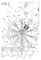
- the reference numeral 1 generally indicates an apparatus for the transfer of products, constituted for example by containers 2.
- the apparatus may constitute part of a machine for filling containers 2 with liquid substances which is only partially illustrated and is generally indicated by 3.
- the transfer apparatus 1 comprises feeder means constituted by a horizontal belt conveyor 4 a first portion whereof is arranged to the side of, and is partially surmounted by, a worm-screw or auger conveyor 5 which is driven by a motor 6 and is capable of transferring the containers 2 in succession toward a rotary conveyor 7, adapted to transfer the containers 2 along a curved path.
- the conveyor 7 passes containers 2 in succession to a rotary filling conveyor 8 which, in a manner which is known and thus not described, fills the containers 2 with a liquid and conveys them to a closure station, which is not illustrated for clarification purposes.
- the filling conveyor 8 essentially comprises a drum 9 with a vertical axis which rotates in a clockwise direction as indicated by the arrow 100 in figure 1.
- the filling conveyor 8 peripherally supports a plurality of mutually equidistant housings or seats 10, each of which is adapted to accommodate a container 2 and to retain it by means of suction means constituted for example by a sucker 11.
- the conveyor 7 comprises a rotary conveyor element 12 with a vertical axis which is adapted to transfer the containers 2 along a curved path by rotating anti-clockwise.
- Said rotary conveyor element 12 is keyed on the upper portion of a vertical hollow shaft 13 which is rotated by motor means, not illustrated, by means of a gearwheel 14 which is keyed to its lower end.
- the shaft 13 is rotatably supported, below the conveyor element 12, by means of a sleeve 15 which is rigidly associated with a horizontal wall 16, advantageously constituting a portion of the base of the filling machine 3, and being arranged coaxial to a lower portion of said shaft 13. Due to reasons which will become apparent hereinafter, said lower portion is connected to a source of compressed air 17.
- a cup-shaped body 18, with its concavity directed upward, is coaxially connected to an upper portion of the sleeve 15 and coaxially supports an annular supporting element 19 which is arranged horizontally.
- the conveyor element 12 comprises a cup-like body 20 which has its concavity directed upward, is keyed coaxially on the shaft 13 directly above the sleeve 15 and supports, in an upward position, a plurality of radially slidable retention elements or holder means 23 (ten in the illustrated case) by means of radial rails 21 defined in an upper surface 22 of said body 20.
- Each retention element 23 comprises a slider 24 adapted to slide within a respective rail 21, which supports a rest element 25 at an end thereof directed toward the outside of the conveyor element 12.
- a retention means, constituted by a sucker 26, protrudes toward the outside of the conveyor element 12 through each rest element 25.
- Each sucker 26 communicates through a duct 27, to an intermediate portion of a vertical duct 28 which is defined in a block 29, supported by a lower wall of the cup-like body 20.
- the duct 28 has an upper end which communicates with the atmosphere and a lower end connected, by means of a duct 30, to a valve element 31 which is also supported by a lower portion of the cup-like body 20.
- Each of the ducts 28 is in the shape of a Venturi tube and has an intermediate neck-like portion to which the duct 27 leads.
- Each valve element 31 has its own inlet connected to the inside of the hollow shaft 13 which, according to what has been described, is connected to the compressed air source 17, and has its outlet connected to the lower end of the related duct 28.
- Each valve element 31 can be actuated, so as to activate or cutoff the connection between the related sucker 26 and the inside of the hollow shaft 13, by a fixed cam means 32 which is supported by the upper surface of the cup-like body 18.
- An adjustment means 33 abuts against the upper surface of the sliders 24 and comprises a disk-like element 34 which is rotatably and coaxially supported by the shaft 13 by means of a sleeve 34′, coaxial to said shaft 13 and constituting an upper extension of a central portion of the cup-like body 20.
- Said disk-like element 34 is traversed, in a downward position, by an actuation means, advantageously constituted by a planar thread 35, which can have one or more starts.
- the thread 35 substantially has the shape of an Archimedean spiral and grips engagement means, expediently constituted by flanking grooves 36, provided on the upper surface of the sliders 24.
- the shaft 13 coaxially and rotatably supports a tubular element 38 which rests, with its lower end, on the upper surface of the disk-like element 34 and is surmounted by a plate 39 which is coaxial to the shaft 13 and is in turn surmounted by a locking element 40.
- Said locking element 40 is constituted by a vertical stem 41 which is threaded and screwed on the upper end of the shaft 13 in a downward position and has an actuation handgrip 42 in an upward position.
- the upper end of the tubular element 38 has a lateral annular protrusion 43 which acts against, in an upward position, a helical spring 44 which is coiled around said tubular element 38 and has a lower end arranged in contact with the upper surface of the disk-like element 34.
- the containers 2 are fed in succession, by means of the belt conveyor 4 and the auger conveyor 5, into contact with respective rest elements 25 and with respective follower elements 37 of the conveyor element 12.
- the containers 2 are retained in contact with said follower elements 37 by the related suckers 26.
- the suckers 26 in fact start to aspirate at the instant in which they receive a container 2, since the valve element 31, under the action of the cam means 32, connects said end of the duct 27 to the inner cavity of the shaft 13, which communicates with the compressed air source 17.
- the containers 2, sliding on the upper surface of the annular element 19, are then conveyed in succession into respective seats 10 of the filling conveyor 8 to which said containers 2 are passed as a consequence of a further actuation of the valve element 31 by the cam means 32.
- Said approach or spacing-apart has the effect of modifying the position of the suckers 26 so as to create, between the pairs of contiguous follower elements 37, a space with such dimensions as to be able to accommodate, in a correct position, a container with different dimensions.
- the disk-like element 34 must then be positioned, with a small rotation about its own axis which does not appreciably affect the position assumed by the suckers 26, so that the follower elements 37 become arranged in such a position as to correctly contact, in a rearward position with reference to the direction of rotation of the conveyor 7, the containers with different dimensions which said conveyor 7 is to convey.
- the stem 41 of the locking element 40 is then screwed back onto the shaft 13 by acting on the actuation handgrip 42 so as to cause the tubular element 38 to firmly engage the upper surface of the disk-like element 34 in abutment engagement relationship therewith, and to rigidly reassociate said disk-like element 34 with the shaft 13.
- the machine is adjusted for the handling of differently sized containers and is ready to be restarted.
- the follower elements 37 may be omitted, since the suckers 26 may be used alone to keep the containers 2 arranged in contact with the rest elements 25.
- the disk-like element 34 may furthermore be replaced with any equivalent kinematic system capable of producing the described radial displacement of the sliders 24.
- suckers 26 may lead directly, by means of the related valve elements 31, to a suction pump 17′ instead of to the compressed air source 17.
- the disk-like element 34 is connected, in an upward position, to a circular plate 45 which is coaxial to the shaft 13 and is keyed to the upper end of a shaft 46 which is contained coaxially within said shaft 13.
- the lower end of the shaft 46 protrudes downward from the shaft 13 and is connected to the output shaft of a motor 47 which is constituted, for example, by a step motor powered by means of sliding brushes 48 arranged resting on a commutator 49 of said motor 47.
- the inner cavity of the shaft 13 communicates, by means of holes 50 defined in the surface of said shaft 13, with a duct 51 which leads to a source of suction which is not illustrated.
- the disk-like element 34 is positioned by the motor 47 so that the follower elements 37 arrange themselves in such a position as to correctly adhere in a rearward position to the containers with new dimensions which said conveyor 7 is to convey.
Landscapes
- Engineering & Computer Science (AREA)
- Mechanical Engineering (AREA)
- Specific Conveyance Elements (AREA)
- Filling Of Jars Or Cans And Processes For Cleaning And Sealing Jars (AREA)
- Supplying Of Containers To The Packaging Station (AREA)
- Branching, Merging, And Special Transfer Between Conveyors (AREA)
Claims (7)
- Vorrichtung zum Fördern von Behältern mit Förder-Mitteln, die durch einen Rotationsförderer (7) gebildet ist, der eine Mehrzahl von Haltevorrichtungen (23) mit gegenseitigem, gleichmäßigem Winkelabstand aufweist, von denen jede dazu bafähigt ist, ein einzelnes Produkt (2) aufzunehmen, wobei eine jede der genannten Haltevorrichtungen (23) in dar Weise angeordnet ist, daß sie in einer im wesentlichen radialen Richtung auf dem Rotationsförderer (7) verschiebbar ist, wobei ferner eine Einstellvorrichtung (34) vorgesehen ist, um die Position dar genannten Haltevorrichtung (23) in der genannten im wesentlichen radialen Richtung in Bezug auf den genannten Rotationsförderer (7) zu ändern, dadurch gekennzeichnet, daß jede Haltevorrichtung (23) in dem genannten Rotationsförderer in verschiabbarer Weise angeordnet ist und eine Saugvorrichtung (26) aufweist, welche von einem entsprechenden Gleitelement (24) getragen ist, das in Bezug auf den genannten Rotationsförderer (7) in radialer Richtung verschiebbar ist, wobei das genannte Gleitelement (24) Einrück- bzw. Eingriffs-Mittel (36) für die genannte Einstellvorrichtung (34) aufweist, wobei die genannte Einstellvorrichtung Betätigungsmittal (35) aufweist, die mit den genannten Einrück- oder Eingriffs-Mitteln (36) in Eingriff gelangen und dazu befähigt sind, die radiale Verschiebung des genannten Gleitelementes (24) in Bezug auf den genannten Rotationsförderer (7) zu verursachen, und wobei die genannte Einstellvorrichtung ein scheibenartiges Element (34) aufweist, welches in Bezug auf den genannten Rotationsförderer (7) koaxial angeordnet ist und eine flache Spiralwindung (35) aufweist, welche einen Bestandteil der genannten Betätigungsmittel bildet und welche die genannten Einrück- oder Eingriffe-Mittel (36) ergreift, wobei die genannten Eingriffs- oder Einrück-Mittel Nuten (36) aufweisen, welche auf einer Oberfläche eines jeden der genannten Gleitelemente (24) vorgesehen sind und die genannte flache Spiralwindung (35) ergreifen.
- Vorrichtung nach Anspruch 1, dadurch gekennzeichnet, daß eine jede der genannten Haltevorrichtungen (23) Folgeoder Mitnehmerelemente (37) aufweist, welche zusammen mit dem genannten Rotationsförderer (7) drehbar sind und in Bezug auf die entsprechenden Saugvorrichtungen (26) stromaufwärts in Bezug auf die Richtung der Drehung des genannten Rotationsförderers (7) angeordnet sind, wobei die genannten Folge- oder Mitnehmer-Elements (37) mit dem genannten scheibenartigen Element (34) starr verbunden sind.
- Vorrichtung nach Anspruch 1, dadurch gekennzeichnet, daß sie ferner Motormittel (47) aufweist, welche dazu befähigt sind, auf die genannte Einstellvorrichtung (34) einzuwirken, um die Position der genannten Haltevorrichtung (23) zu verändern.
- Vorrichtung noch Anspruch 3, dadurch gekennzeichnet, daß die genannten Motormittel einen Schrittmotor (47) aufweisen.
- Vorrichtung gemäß einem der Ansprüche 1 bis 3, dadurch gekennzeichnet, daß die genannten Saugvorrichtungen (26) zu einem Hals einer Leitung (28) führen, welche im Innern als ein Venturirohr geformt ist, wobei eine Druckluftquelle (17) vorgesehen ist, wobei ferner eine Ventilvorrichtung (31) vorgesehen ist, um die genannte Druckluftquelle (17) mit einem Ende der genannten Leitung (28) zu verbinden.
- Vorrichtung nach einem der Ansprüche 1 bis 5, dadurch gekennzeichnet, daß die genannten Saugvorrichtungen (26) zu einer Saugpumpe (17') führen, wobei eine Ventilvorrichtung (31) vorgesehen ist, um die genannten Saugvorrichtungen (26) mit der genannten Saugpumpe (17') zu verbinden.
- Vorrichtung gemäß Anspruch 1, dadurch gekennzeichnet, daß die genannten Betätigungsmittel (35) dazu befähigt sind, gleichzeitig eine gleiche radiale Verschiebung sämtlicher der genannten Gleitelemente (24) in Bezug auf den genannten Rotationsförderer (7) zu verursachen.
Applications Claiming Priority (2)
| Application Number | Priority Date | Filing Date | Title |
|---|---|---|---|
| IT8903504A IT1233303B (it) | 1989-06-07 | 1989-06-07 | Apparecchiatura per il convogliamento di prodotti |
| IT350489 | 1989-06-07 |
Publications (3)
| Publication Number | Publication Date |
|---|---|
| EP0401698A2 EP0401698A2 (de) | 1990-12-12 |
| EP0401698A3 EP0401698A3 (de) | 1991-06-05 |
| EP0401698B1 true EP0401698B1 (de) | 1994-08-24 |
Family
ID=11108619
Family Applications (1)
| Application Number | Title | Priority Date | Filing Date |
|---|---|---|---|
| EP90110459A Expired - Lifetime EP0401698B1 (de) | 1989-06-07 | 1990-06-01 | Fördervorrichtung für Gegenstände |
Country Status (6)
| Country | Link |
|---|---|
| US (1) | US5058731A (de) |
| EP (1) | EP0401698B1 (de) |
| JP (1) | JPH0326607A (de) |
| DE (1) | DE69011749T2 (de) |
| ES (1) | ES2057273T3 (de) |
| IT (1) | IT1233303B (de) |
Cited By (11)
| Publication number | Priority date | Publication date | Assignee | Title |
|---|---|---|---|---|
| WO2011139565A1 (en) | 2010-05-07 | 2011-11-10 | The Procter & Gamble Company | Adjustable star wheel |
| WO2011139577A1 (en) | 2010-05-07 | 2011-11-10 | The Procter & Gamble Company | Universally adjustable star wheel |
| AU2008303374B2 (en) * | 2007-09-24 | 2013-06-13 | Zepf Technologies Uk Limited | Adjustable star wheel |
| WO2013109414A1 (en) | 2012-01-17 | 2013-07-25 | The Procter & Gamble Company | Adjustable guide rail assemblies |
| WO2015071111A1 (de) | 2013-11-12 | 2015-05-21 | Khs Gmbh | Transportstern mit verstellbaren sterntaschen – noniusstern |
| DE102013113292A1 (de) | 2013-12-02 | 2015-06-18 | Khs Gmbh | Transportstern mit verstellbaren Sterntaschen |
| US9181043B1 (en) | 2014-06-03 | 2015-11-10 | The Procter & Gamble Company | Elevation change system for a rotary device |
| US9302856B2 (en) | 2014-06-03 | 2016-04-05 | The Procter & Gamble Company | Method for adjusting a rotary device |
| US9371195B2 (en) | 2014-06-03 | 2016-06-21 | The Procter & Gamble Company | Adjustment system for a rotary device |
| DE102017219503A1 (de) | 2017-11-02 | 2019-05-02 | Bausch + Ströbel Maschinenfabrik Ilshofen GmbH + Co. KG | Verstellbares Vakuumrad |
| US10315860B2 (en) | 2016-05-25 | 2019-06-11 | The Procter And Gamble Company | Article handling device |
Families Citing this family (22)
| Publication number | Priority date | Publication date | Assignee | Title |
|---|---|---|---|---|
| ATE106952T1 (de) * | 1990-04-20 | 1994-06-15 | Balzers Hochvakuum | Vorrichtung zur halterung und kühlung nebeneinander angeordneter werkstücke and träger für mehrere vorrichtungen. |
| CH687248A5 (de) * | 1991-10-30 | 1996-10-31 | Mitsubishi Heavy Ind Ltd | Dosenzufuehreinrichtung fuer eine Dosenverschliessmaschine. |
| GB9314647D0 (en) * | 1993-07-15 | 1993-08-25 | Pakcentre Limited | Methods for conveying objects through apparatus,packing apparatus and methods for packing materials in cartons |
| JP3563108B2 (ja) * | 1994-05-27 | 2004-09-08 | 株式会社アドバンテスト | Icテストハンドラのデバイス搬送機構 |
| US5681597A (en) * | 1996-02-06 | 1997-10-28 | Liquid Container L.P. | Vacuum conveyor picker for blow bottle container |
| WO2000027709A1 (en) * | 1998-11-05 | 2000-05-18 | Sepha Limited | Rotary deblistering apparatus |
| EA200401111A1 (ru) | 2002-02-25 | 2005-02-24 | Диффьюжн Фармасьютикалз Ллс | Биполярные соли транс-каротиноидов и их применение |
| UA95903C2 (ru) | 2005-02-24 | 2011-09-26 | Дифьюжен Фармасьютикалз Ллк | Транс-каротиноиды, их синтез, лекарственная форма и применение |
| US20080092569A1 (en) * | 2006-10-20 | 2008-04-24 | Doberstein Andrew J | Cooling unit with multi-parameter defrost control |
| CN101687757A (zh) | 2007-04-13 | 2010-03-31 | 扩散药品有限公司 | 双极性反式类胡萝卜素作为预治疗及其在周围血管疾病的治疗中的应用 |
| JP2011502125A (ja) | 2007-10-31 | 2011-01-20 | ディフュージョン・ファーマシューティカルズ・エルエルシー | 小分子拡散を促進する新しい種類の治療法 |
| ITPR20080039A1 (it) | 2008-06-10 | 2009-12-11 | Lanfranchi Srl | Macchina per ordinare ed allineare contenitori in plastica cumulati in maniera disordinata. |
| KR101891357B1 (ko) | 2010-06-02 | 2018-08-24 | 디퓨젼 파마슈티컬즈 엘엘씨 | 양극성 트랜스 카로티노이드의 경구용 제형 |
| DE102011111321A1 (de) | 2011-08-26 | 2013-02-28 | Khs Gmbh | Füllvorrichtung |
| FR3026097B1 (fr) * | 2014-09-19 | 2017-09-29 | Visio Nerf | Dispositif de transfert de pieces en defilement |
| ES2631006T3 (es) * | 2014-11-24 | 2017-08-25 | Jaime Martí Sala | Transformador rotativo con cambio de paso para transferir contenedores |
| CN106552878B (zh) * | 2016-11-08 | 2019-01-25 | 广州庆达汽车零部件有限公司 | 一种汽车前副车架钣金件自动送料加工装置 |
| CN106583574B (zh) * | 2016-11-26 | 2019-01-11 | 宁波宏科汽车部件有限公司 | 一种汽车横梁焊接分总成冲压送料机构 |
| CN108820915B (zh) * | 2018-06-12 | 2020-07-14 | 无锡市盛宝嘉科技有限公司 | 一种自动化旋转料仓 |
| CN114435952B (zh) * | 2022-03-02 | 2022-09-06 | 广东建嵘智能设备有限公司 | 一种包装容器的状态调整装置、整理系统以及整理方法 |
| CN114589372B (zh) * | 2022-04-22 | 2022-11-04 | 明光市锐创电气有限公司 | 一种小型变压器下料机构及其焊锡加工系统 |
| CN115351570A (zh) * | 2022-09-01 | 2022-11-18 | 宁波海信紧固件有限公司 | 一种防松螺母内圈圆角加工设备 |
Citations (1)
| Publication number | Priority date | Publication date | Assignee | Title |
|---|---|---|---|---|
| JPS518077A (ja) * | 1974-07-09 | 1976-01-22 | Tokico Ltd | Unbinsochi |
Family Cites Families (5)
| Publication number | Priority date | Publication date | Assignee | Title |
|---|---|---|---|---|
| GB1419247A (en) * | 1972-02-17 | 1975-12-24 | Jackson J M | Take off and stacker for container printing machine |
| US3961697A (en) * | 1974-03-20 | 1976-06-08 | R. A. Jones & Company Inc. | Apparatus for shingling and packing of articles |
| DE3143511A1 (de) * | 1981-11-03 | 1983-05-11 | Pirzer, Carl, 8402 Neutraubling | Ein- und auslaufstern |
| DE3760733D1 (en) * | 1986-05-23 | 1989-11-16 | Uhlmann Maschf Josef | Device for picking-up, transferring and depositing flat packaging articles for packaging machines |
| JP2615893B2 (ja) * | 1988-08-17 | 1997-06-04 | 澁谷工業株式会社 | 回転式物品処理装置 |
-
1989
- 1989-06-07 IT IT8903504A patent/IT1233303B/it active
-
1990
- 1990-05-23 US US07/527,400 patent/US5058731A/en not_active Expired - Fee Related
- 1990-06-01 ES ES90110459T patent/ES2057273T3/es not_active Expired - Lifetime
- 1990-06-01 DE DE69011749T patent/DE69011749T2/de not_active Expired - Fee Related
- 1990-06-01 EP EP90110459A patent/EP0401698B1/de not_active Expired - Lifetime
- 1990-06-07 JP JP2147541A patent/JPH0326607A/ja active Pending
Patent Citations (1)
| Publication number | Priority date | Publication date | Assignee | Title |
|---|---|---|---|---|
| JPS518077A (ja) * | 1974-07-09 | 1976-01-22 | Tokico Ltd | Unbinsochi |
Cited By (16)
| Publication number | Priority date | Publication date | Assignee | Title |
|---|---|---|---|---|
| AU2008303374B2 (en) * | 2007-09-24 | 2013-06-13 | Zepf Technologies Uk Limited | Adjustable star wheel |
| US9340364B2 (en) | 2010-05-07 | 2016-05-17 | The Procter & Gamble Company | Automated adjustment system for star wheel |
| WO2011139577A1 (en) | 2010-05-07 | 2011-11-10 | The Procter & Gamble Company | Universally adjustable star wheel |
| US8418836B2 (en) | 2010-05-07 | 2013-04-16 | The Procter & Gamble Company | Universally adjustable star wheel |
| US8813950B2 (en) | 2010-05-07 | 2014-08-26 | The Procter & Gamble Company | Automated adjustment system for star wheel |
| US8820514B2 (en) | 2010-05-07 | 2014-09-02 | The Procter & Gamble Company | Universally adjustable star wheel |
| WO2011139565A1 (en) | 2010-05-07 | 2011-11-10 | The Procter & Gamble Company | Adjustable star wheel |
| WO2013109414A1 (en) | 2012-01-17 | 2013-07-25 | The Procter & Gamble Company | Adjustable guide rail assemblies |
| WO2015071111A1 (de) | 2013-11-12 | 2015-05-21 | Khs Gmbh | Transportstern mit verstellbaren sterntaschen – noniusstern |
| DE102013113292A1 (de) | 2013-12-02 | 2015-06-18 | Khs Gmbh | Transportstern mit verstellbaren Sterntaschen |
| US9302856B2 (en) | 2014-06-03 | 2016-04-05 | The Procter & Gamble Company | Method for adjusting a rotary device |
| US9181043B1 (en) | 2014-06-03 | 2015-11-10 | The Procter & Gamble Company | Elevation change system for a rotary device |
| US9371195B2 (en) | 2014-06-03 | 2016-06-21 | The Procter & Gamble Company | Adjustment system for a rotary device |
| US10315860B2 (en) | 2016-05-25 | 2019-06-11 | The Procter And Gamble Company | Article handling device |
| DE102017219503A1 (de) | 2017-11-02 | 2019-05-02 | Bausch + Ströbel Maschinenfabrik Ilshofen GmbH + Co. KG | Verstellbares Vakuumrad |
| US11261037B2 (en) | 2017-11-02 | 2022-03-01 | Bausch + Ströbel Maschinenfabrik Ilshofen GmbH + Co. KG | Adjustable vacuum wheel |
Also Published As
| Publication number | Publication date |
|---|---|
| EP0401698A2 (de) | 1990-12-12 |
| ES2057273T3 (es) | 1994-10-16 |
| EP0401698A3 (de) | 1991-06-05 |
| US5058731A (en) | 1991-10-22 |
| IT8903504A0 (it) | 1989-06-07 |
| DE69011749D1 (de) | 1994-09-29 |
| DE69011749T2 (de) | 1995-02-16 |
| JPH0326607A (ja) | 1991-02-05 |
| IT1233303B (it) | 1992-03-26 |
Similar Documents
| Publication | Publication Date | Title |
|---|---|---|
| EP0401698B1 (de) | Fördervorrichtung für Gegenstände | |
| EP0113703B1 (de) | Kombinierte Maschine zum Zusammensetzen von Teilen von Behältern | |
| EP1597150B1 (de) | Vorrichtung zum formen von behältern | |
| US2359932A (en) | Closure applying machine | |
| CN111873636A (zh) | 一种立式安瓿瓶彩喷印字生产线 | |
| US3753509A (en) | Bottle uncaser-single liner | |
| EP0399354B1 (de) | Vorrichtung zum korrekten Positionieren von auf Behältern anzubringenden Abgabeorganen | |
| GB2029786A (en) | Apparatus for forming and overwrapping batches of products | |
| EP0486439B1 (de) | Anordnung zum synchronen Antrieb von Einrichtungen zur Füllung und Containerbehandlung in Getränkeabfüllern | |
| US4594768A (en) | Trimming ceramic flatware | |
| CN212422556U (zh) | 一种立式安瓿瓶彩喷印字生产线 | |
| US2294274A (en) | Apparatus for handling biscuits and like articles | |
| CN1065200A (zh) | 胶囊充填设备 | |
| US2319900A (en) | Apparatus for packing foodstuffs in cans | |
| JPH0466414A (ja) | 容器処理装置 | |
| CN221363591U (zh) | 一种用于装配伸缩勺子的自动组装设备 | |
| EP0373396A1 (de) | Vorrichtung zum Befüllen von Behältern | |
| WO1987002623A1 (en) | Automatic handling and screen printing apparatus | |
| EP0483712B1 (de) | Verschliessmaschine für Behälter | |
| US3176823A (en) | Transfer mechanism for tubular articles | |
| JP4005309B2 (ja) | 異なる2種類のカートンのためのフィーダ機構及びホッパー | |
| US4907504A (en) | Apparatus for repositioning containers | |
| EP1808376B1 (de) | Vorrichtung und Verfahren zum Trennen der Öffnungselemente geliefert in Form einer Folie die einzeln auf den jeweiligen Verpackungen, für fliessfähige Nahrungsmittel angebracht werden | |
| US3089614A (en) | Dispenser for conical members | |
| US2156951A (en) | Can filling machine |
Legal Events
| Date | Code | Title | Description |
|---|---|---|---|
| PUAI | Public reference made under article 153(3) epc to a published international application that has entered the european phase |
Free format text: ORIGINAL CODE: 0009012 |
|
| AK | Designated contracting states |
Kind code of ref document: A2 Designated state(s): DE ES FR GB |
|
| PUAL | Search report despatched |
Free format text: ORIGINAL CODE: 0009013 |
|
| AK | Designated contracting states |
Kind code of ref document: A3 Designated state(s): DE ES FR GB |
|
| 17P | Request for examination filed |
Effective date: 19911004 |
|
| 17Q | First examination report despatched |
Effective date: 19930312 |
|
| GRAA | (expected) grant |
Free format text: ORIGINAL CODE: 0009210 |
|
| AK | Designated contracting states |
Kind code of ref document: B1 Designated state(s): DE ES FR GB |
|
| REF | Corresponds to: |
Ref document number: 69011749 Country of ref document: DE Date of ref document: 19940929 |
|
| REG | Reference to a national code |
Ref country code: ES Ref legal event code: FG2A Ref document number: 2057273 Country of ref document: ES Kind code of ref document: T3 |
|
| ET | Fr: translation filed | ||
| PLBE | No opposition filed within time limit |
Free format text: ORIGINAL CODE: 0009261 |
|
| STAA | Information on the status of an ep patent application or granted ep patent |
Free format text: STATUS: NO OPPOSITION FILED WITHIN TIME LIMIT |
|
| 26N | No opposition filed | ||
| PGFP | Annual fee paid to national office [announced via postgrant information from national office to epo] |
Ref country code: FR Payment date: 19980422 Year of fee payment: 9 |
|
| PGFP | Annual fee paid to national office [announced via postgrant information from national office to epo] |
Ref country code: DE Payment date: 19980522 Year of fee payment: 9 |
|
| PGFP | Annual fee paid to national office [announced via postgrant information from national office to epo] |
Ref country code: GB Payment date: 19980529 Year of fee payment: 9 |
|
| PGFP | Annual fee paid to national office [announced via postgrant information from national office to epo] |
Ref country code: ES Payment date: 19980615 Year of fee payment: 9 |
|
| PG25 | Lapsed in a contracting state [announced via postgrant information from national office to epo] |
Ref country code: GB Free format text: LAPSE BECAUSE OF NON-PAYMENT OF DUE FEES Effective date: 19990601 |
|
| PG25 | Lapsed in a contracting state [announced via postgrant information from national office to epo] |
Ref country code: ES Free format text: LAPSE BECAUSE OF NON-PAYMENT OF DUE FEES Effective date: 19990602 |
|
| PG25 | Lapsed in a contracting state [announced via postgrant information from national office to epo] |
Ref country code: FR Free format text: THE PATENT HAS BEEN ANNULLED BY A DECISION OF A NATIONAL AUTHORITY Effective date: 19990630 |
|
| GBPC | Gb: european patent ceased through non-payment of renewal fee |
Effective date: 19990601 |
|
| PG25 | Lapsed in a contracting state [announced via postgrant information from national office to epo] |
Ref country code: DE Free format text: LAPSE BECAUSE OF NON-PAYMENT OF DUE FEES Effective date: 20000503 |
|
| REG | Reference to a national code |
Ref country code: FR Ref legal event code: ST |
|
| REG | Reference to a national code |
Ref country code: ES Ref legal event code: FD2A Effective date: 20010503 |