EP0401778A1 - Endoskop, insbesondere Resektoskop - Google Patents
Endoskop, insbesondere Resektoskop Download PDFInfo
- Publication number
- EP0401778A1 EP0401778A1 EP90110682A EP90110682A EP0401778A1 EP 0401778 A1 EP0401778 A1 EP 0401778A1 EP 90110682 A EP90110682 A EP 90110682A EP 90110682 A EP90110682 A EP 90110682A EP 0401778 A1 EP0401778 A1 EP 0401778A1
- Authority
- EP
- European Patent Office
- Prior art keywords
- endoscope
- protective shield
- optics
- insert
- proximal end
- Prior art date
- Legal status (The legal status is an assumption and is not a legal conclusion. Google has not performed a legal analysis and makes no representation as to the accuracy of the status listed.)
- Granted
Links
- 230000001681 protective effect Effects 0.000 claims abstract description 31
- 230000008878 coupling Effects 0.000 claims description 6
- 238000010168 coupling process Methods 0.000 claims description 6
- 238000005859 coupling reaction Methods 0.000 claims description 6
- 239000007788 liquid Substances 0.000 claims description 6
- 239000000463 material Substances 0.000 claims description 3
- 239000013307 optical fiber Substances 0.000 claims 1
- 239000012530 fluid Substances 0.000 abstract description 4
- 238000011010 flushing procedure Methods 0.000 abstract 1
- 208000015181 infectious disease Diseases 0.000 description 4
- 210000001519 tissue Anatomy 0.000 description 4
- 238000000034 method Methods 0.000 description 3
- 238000002271 resection Methods 0.000 description 3
- 230000003287 optical effect Effects 0.000 description 2
- 208000030507 AIDS Diseases 0.000 description 1
- 239000008280 blood Substances 0.000 description 1
- 210000004369 blood Anatomy 0.000 description 1
- 201000010099 disease Diseases 0.000 description 1
- 208000037265 diseases, disorders, signs and symptoms Diseases 0.000 description 1
- 230000000694 effects Effects 0.000 description 1
- 208000006454 hepatitis Diseases 0.000 description 1
- 231100000283 hepatitis Toxicity 0.000 description 1
- 210000004400 mucous membrane Anatomy 0.000 description 1
- 230000000414 obstructive effect Effects 0.000 description 1
- 244000052769 pathogen Species 0.000 description 1
- 230000036316 preload Effects 0.000 description 1
- 210000002307 prostate Anatomy 0.000 description 1
- 210000003813 thumb Anatomy 0.000 description 1
- 238000009423 ventilation Methods 0.000 description 1
Images
Classifications
-
- A—HUMAN NECESSITIES
- A61—MEDICAL OR VETERINARY SCIENCE; HYGIENE
- A61B—DIAGNOSIS; SURGERY; IDENTIFICATION
- A61B90/00—Instruments, implements or accessories specially adapted for surgery or diagnosis and not covered by any of the groups A61B1/00 - A61B50/00, e.g. for luxation treatment or for protecting wound edges
- A61B90/05—Splash shields for protection of the surgeon, e.g. splash guards connected to the apparatus
-
- A—HUMAN NECESSITIES
- A61—MEDICAL OR VETERINARY SCIENCE; HYGIENE
- A61B—DIAGNOSIS; SURGERY; IDENTIFICATION
- A61B1/00—Instruments for performing medical examinations of the interior of cavities or tubes of the body by visual or photographical inspection, e.g. endoscopes; Illuminating arrangements therefor
- A61B1/012—Instruments for performing medical examinations of the interior of cavities or tubes of the body by visual or photographical inspection, e.g. endoscopes; Illuminating arrangements therefor characterised by internal passages or accessories therefor
- A61B1/015—Control of fluid supply or evacuation
-
- A—HUMAN NECESSITIES
- A61—MEDICAL OR VETERINARY SCIENCE; HYGIENE
- A61B—DIAGNOSIS; SURGERY; IDENTIFICATION
- A61B1/00—Instruments for performing medical examinations of the interior of cavities or tubes of the body by visual or photographical inspection, e.g. endoscopes; Illuminating arrangements therefor
- A61B1/307—Instruments for performing medical examinations of the interior of cavities or tubes of the body by visual or photographical inspection, e.g. endoscopes; Illuminating arrangements therefor for the urinary organs, e.g. urethroscopes, cystoscopes
Definitions
- the invention relates to an endoscope, in particular a resectoscope, for resecting tissue, for example in prostate resection, with an endoscope shaft that can be inserted into a body cavity for guiding rinsing fluid and for receiving a work insert that can be actuated at its proximal end, the area of action of which endoscope optics connected to its proximal end is visually controllable.
- Such resectoscopes usually require larger amounts of rinsing fluid, in particular to drain away the resected tissue.
- the procedure is such that after resection of a certain amount of tissue, the work insert is pulled out of the resectoscope shaft inserted into the body cavity in order to lead the resected tissue parts and the rinsing fluid out of the body cavity through the relatively large shaft cross section.
- the rinsing liquid gets into the face of the surgeon performing the endoscopic procedure and following the endoscope optics, since the rinsing liquid is allowed to drain freely into a suitable collecting container at the proximal end of the resectoscope shaft.
- Such a contact with the rinsing liquid is not only perceived by the surgeon as very annoying and unpleasant, but it is also associated with the great risk that this contact can be used to transmit, for example, AIDS and / or hepatitis pathogens through the mucous membranes of the eyes , Nose and mouth get into the blood and can trigger the respective disease.
- a protective shield is releasably attachable to a length section of the endoscope, the length section being formed from the sections of the working insert and the endoscope optics protruding proximally from the endoscope shaft.
- the protective shield and the resectoscope form a unit and the face of the surgeon following the intervention via the resectoscope optics is covered directly in relation to the area of action of the work assignment.
- the protective shield according to the invention can be mounted very simply by plugging it on if it is U-shaped, the two legs being formed by an incision, the width of which essentially corresponds to the diameter of the instrument or optical part receiving the protective shield.
- Particularly secure hold can be achieved in that the protective shield has a central recess, the diameter of which is somewhat smaller than the diameter of the instrument or optical part receiving it, the recess merging into an incision whose width is smaller than the diameter of the aforementioned Recess.
- the part of the protective shield that surrounds the central recess is made of a rigid, elastically deformable part, and the parts that delimit the incision are made of the same or of a flexible material, preferably in each case transparent version, manufactured.
- the soft-elastic design of the legs adjoining the rigid part has an advantageous effect when handling the resectoscope, since these rest on the surface of the hand and follow every hand movement of the surgeon.
- the slot and the recess can be resiliently deformed within limits, so that the protective shield can be securely fixed on the instrument part or the optics by the spring preload resulting from the deformation.
- the protective shield can have a coupling part in the region of the recess, so that, for example, an arrangement or fixing between the endoscope optics and the work insert is possible.
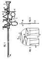
- FIG. 1 shows an endoscope in the form of a resectoscope, as is used in practice. It essentially comprises a resectoscope shaft 1 with a handle 2 and an inlet connection 3 for the rinsing liquid.
- the Resectoscope shaft 1 serves to receive and pass through a known working insert 4 with a thumb ring 5 and a high-frequency current connection 6 for a resection loop 6a and a known endoscope optic 8 with a light guide connection 9 detachably connected to the working insert 4 by means of a proximal-side coupling 7.
- a protective shield 10 is preferably arranged between the light guide connection 9 of the endoscope optics 8 and the coupling 7.
- the protective shield 10 has a web part 11 made of a rigid material, to which elastically designed parts 12 connect in a non-detachable manner, which give the protective shield 10 a U-shaped shape, the parts 12 having the one incision 13 form a limiting leg of this U-shape.
- a recess 14 In the center of the protective shield 10 there is a recess 14, at the upper end of which a radial relief slot 15 is provided, the dimension of which is selected such that the deformation occurring on the protective shield 10 when plugged in remains in the elastic range, so that the resulting restoring force is one causes the protective shield 10 to be securely held on the corresponding instrument part.
- the size or spatial shape of the protective shield 10 in a suitable manner in order to optimize the protective effect. It can also be curved towards the patient.
Landscapes
- Health & Medical Sciences (AREA)
- Surgery (AREA)
- Life Sciences & Earth Sciences (AREA)
- Heart & Thoracic Surgery (AREA)
- Molecular Biology (AREA)
- Oral & Maxillofacial Surgery (AREA)
- Engineering & Computer Science (AREA)
- Biomedical Technology (AREA)
- Nuclear Medicine, Radiotherapy & Molecular Imaging (AREA)
- Medical Informatics (AREA)
- Pathology (AREA)
- Animal Behavior & Ethology (AREA)
- General Health & Medical Sciences (AREA)
- Public Health (AREA)
- Veterinary Medicine (AREA)
- Endoscopes (AREA)
- Surgical Instruments (AREA)
Abstract
Description
- Die Erfindung betrifft ein Endoskop, insbesondere Resektoskop, zum Resizieren von Gewebe beispielsweise bei der Prostataresektion, mit einem in eine Körperhöhle einführbaren Endoskopschaft zur Leitung von Spülflüssigkeit und zur Aufnahme eines an seinem proximalen Ende betätigbaren Arbeitseinsatzes, dessen Wirkungsbereich über eine mit seinem proximalen Ende verbundene Endoskopoptik visuell kontrollierbar ist.
- Bei derartigen Resektoskopen werden üblicherweise größere Mengen Spülflüssigkeit benötigt, um insbesondere die resizierten Gewebeteile abzuführen. Dabei wird so vorgegangen, daß nach erfolgter Resektion einer bestimmten Gewebemenge der Arbeitseinsatz aus dem in die Körperhöhle eingeführten Resektoskopschaft herausgezogen wird, um durch den relativ großen Schaftquerschnitt die resizierten Gewebeteile und die Spülflüssigkeit aus der Körperhöhle herauszuführen.
- Bei der Handhabung des Resektoskopes ist es in der Regel unvermeidbar, das Spülflüssigkeit in das Gesicht des den endoskopischen Eingriff durchführenden und über die Endoskopoptik verfolgenden Operateurs gelangt, da man die Spülflüssigkeit an dem proximalseitigen Ende des Resektoskopschaftes in einen geeigneten Auffangbehälter frei ablaufen läßt. Ein derartiger Kontakt mit der Spülflüssigkeit wird von dem Operateur nicht nur als sehr störend und unangenehm empfunden, sondern es ist damit auch die große Gefahr verbunden, daß durch diesen Kontakt beispielsweise Aids- und/oder Hepatitiserreger übertragen werden können, die über die Schleimhäute von Augen, Nase und Mund in das Blut gelangen und die jeweilige Krankheit auslösen können.
- Um derartige Infektionen zu vermeiden bzw. das Infektionsrisiko zu reduzieren, sind transparente, vor dem Gesicht zu tragende Schutzmasken in Anwendung. Das Tragen solcher Gesichtsmasken wird jedoch aufgrund des relativ geringen Tragekomforts sowie der schlechten Hinterlüftung als sehr störend empfunden. Schutzbrillen und Mundschutz tragen ebenfalls zur Reduzierung des Infektionsrisikos bei, können dieses jedoch ebensowenig vollständig ausschließen. Im übrigen sind auch derartige Hilfsmittel unbeliebt, da sie als bei der Durchführung des Eingriffes störend empfunden werden.
- Es ist die Aufgabe der Erfindung, den einen endoskopischen Eingriff ausführenden Operateur vor der Gefahr einer Infektion durch umherspritzende Spülflüssigkeit sicher zu schützen, ohne daß dieser hinderliche oder sonstwie störende Hilfsmittel anlegen muß.
- Diese Aufgabe wird erfindungsgemäß dadurch gelöst, daß ein Schutzschild auf einem Längenabschnitt des Endoskops lösbar befestigbar ist, wobei der Längenabschnitt aus den aus dem Endoskopschaft proximal herausragenden Abschnitten des Arbeitseinsatzes und der Endoskopoptik gebildet ist.
- Die damit erzielbaren Vorteile bestehen insbesondere darin, daß der Schutzschild und das Resektoskop eine Einheit bilden und das Gesicht des den Eingriff über die Resektoskopoptik verfolgenden Operateurs gegenüber dem Wirkungsbereich des Arbeitseinsatzes unmittelbar abgedeckt ist.
- Der erfindungsgemäße Schutzschild läßt sich sehr einfach durch Aufstecken montieren, wenn dieser U-förmig ausgebildet ist, wobei die beiden Schenkel durch einen Einschnitt gebildet sind, dessen Breite dem Durchmesser des den Schutzschild aufnehmenden Instrumenten- oder Optikteiles im wesentlichen entspricht. Besonders sicherer Halt kann dabei dadurch erreicht werden, daß der Schutzschild eine zentrale Ausnehmung aufweist, deren Durchmesser erwas geringer als der Durchmesser des diesen aufnehmenden Instrumenten- oder Optikteiles ist, wobei die Ausnehmung in einen Einschnitt übergeht, dessen Breite kleiner ist als der Durchmesser der vorerwähnten Ausnehmung.
- Nach einer Ausgestaltung der Erfindung sind der die zentrale Ausnehmung umschließende Teil des Schutzschildes aus einem starren, elastisch verformbaren, und die den Einschnitt begrenzenden Teile aus dem gleichen oder aus einem weichelastischen Werkstoff, vorzugsweise jeweils transparenter Ausführung, gefertigt. Die weichelastische Ausbildung der sich an den starren Teil anschließenden Schenkel wirkt sich vorteilhaft bei der Handhabung des Resektoskopes aus, da diese sich an die Handoberfläche anlegen und jeder Handbewegung des Operateurs folgen.
- Durch den sich an den oberen Teil der Ausnehmung anschließenden Einschnitt kann der der Schlitz und die Ausnehmung in Grenzen federelastisch verformt werden, so daß der Schutzschild durch die aus der Verformung resultierende Federvorspannung sicher auf dem Instrumenteil oder der Optik festgelegt werden kann.
- Gemäß einer anderen Ausgestaltung kann der Schutzschild im Bereich der Ausnehmung einen Kupplungsteil aufweisen, so daß beispielsweise eine Anordnung bzw. Festlegung zwischen der Endoskopoptik und dem Arbeitseinsatz möglich ist.
- Die Erfindung ist nachfolgend anhand eines in der Zeichnung dargestellten Ausführungsbeispieles näher erläutert. Es zeigen:
- Figur 1 ein Resektoskop mit einem Schutzschild,
- Figur 2 den erfindungsgemäßen Schutzschild in Aufsicht und vergrößert dargestellt,
- Figur 3 den Schutzschild nach Figur 2 in Seitenansicht.
- Die Figur 1 gibt ein Endoskop in Form eines Resektoskops wieder, wie es in der Praxis eingesetzt wird. Es umfaßt im wesentlichen einen Resektoskopschaft 1 mit einer Handhabe 2 und einem Zulaufstutzen 3 für die Spülflüssigkeit. Der Resektoskopschaft 1 dient der Aufnahme und Hindurchführung eines bekannten Arbeitseinsatzes 4 mit einem Daumenring 5 und einem Hochfrequenz-Stromanschluß 6 für eine Resektionsschlinge 6a sowie einer bekannten, mittels einer proximalseitigen Kupplung 7 lösbar mit dem Arbeitseinsatz 4 verbundenen Endoskopoptik 8 mit einem Lichtleiteranschluß 9.
- Ein erfindungsgemäßer Schutzschild 10 ist in dem gezeigten Ausführungsbeispiel vorzugsweise zwischen dem Lichtleiteranschluß 9 der Endoskopoptik 8 und der Kupplung 7 angeordnet. Wie in Figur 2 erkennbar ist, weist der Schutzschild 10 einen Stegteil 11 aus einem starren Werkstoff aus, an den sich elastisch ausgebildete Teile 12 unlösbar befestigt anschließen, die dem Schutzschild 10 eine U-förmige Gestalt geben, wobei die Teile 12 die einen Einschnitt 13 begrenzenden Schenkel dieser U-Gestalt bilden. Im Zentrum des Schutzschildes 10 befindet sich eine Ausnehmung 14, an deren oberem Ende ein radialer Entlastungsschlitz 15 vorgesehen ist, dessen Dimension so gewählt ist, daß die auf den Schutzschild 10 beim Aufstecken auftretende Verformung im elastischen Bereich verbleibt, so daß die daraus resultierende Rückstellkraft eine sichere Halterung des Schutzschildes 10 auf dem entsprechenden Instrumententeil bewirkt.
- In weiterer, nicht gezeigter Ausbildung des erfindungsgemäßen Schutzschildes 10 ist es denkbar, für die lösbare Befestigung desselben auf dem Arbeitseinsatz 4 oder der Endoskopoptik 8 Befestigungsmittel vorzusehen, die eine form- oder kraftschlüssige Fixierung ermöglichen. Auch ein Kupplungsteil kann vorgesehen sein. Solche Kupplungsteile haben gegenüber der eingangs beschriebenen Ausführugnsform des Schutzschildes 10 den Vorteil der besseren Fixierung zwischen den jeweiligen Instrumententeilen.
- Es ist ferner denkbar, zur Optimierung des Schutzeffektes die Größe oder Raumform des Schutzschildes 10 in geeigneter Weise anzupassen. Dabei kann dieser auch in Richtung zum Patienten hin gekrümmt sein.
Claims (6)
Applications Claiming Priority (2)
| Application Number | Priority Date | Filing Date | Title |
|---|---|---|---|
| DE3918719A DE3918719A1 (de) | 1989-06-08 | 1989-06-08 | Endoskop, insbesondere resektoskop |
| DE3918719 | 1989-06-08 |
Publications (2)
| Publication Number | Publication Date |
|---|---|
| EP0401778A1 true EP0401778A1 (de) | 1990-12-12 |
| EP0401778B1 EP0401778B1 (de) | 1994-07-27 |
Family
ID=6382354
Family Applications (1)
| Application Number | Title | Priority Date | Filing Date |
|---|---|---|---|
| EP90110682A Expired - Lifetime EP0401778B1 (de) | 1989-06-08 | 1990-06-06 | Endoskop, insbesondere Resektoskop |
Country Status (3)
| Country | Link |
|---|---|
| US (1) | US5024212A (de) |
| EP (1) | EP0401778B1 (de) |
| DE (2) | DE3918719A1 (de) |
Families Citing this family (15)
| Publication number | Priority date | Publication date | Assignee | Title |
|---|---|---|---|---|
| DE9109924U1 (de) * | 1991-08-08 | 1992-09-10 | BIOMET Deutschland GmbH, 14167 Berlin | Endoskop |
| US5368014A (en) * | 1990-11-21 | 1994-11-29 | Effner Biomet Gmbh | Modular endoscope having easily replaceable parts |
| US5782750A (en) * | 1997-03-06 | 1998-07-21 | Gluskin; Lawrence E. | Endoscopy control end and biopsy channel shield |
| US5947894A (en) * | 1997-11-21 | 1999-09-07 | Endolap, Inc. | Disposable endoscope shield and method |
| USD458368S1 (en) | 2000-07-22 | 2002-06-04 | Karl Storz Gmbh & Co. Kg | Tool holder |
| DE10126542A1 (de) * | 2001-05-30 | 2003-01-02 | Winter & Ibe Olympus | Urologisches Resektoskop mit Federbrücke |
| DE102005039106B4 (de) * | 2005-08-12 | 2010-01-14 | Karl Storz Gmbh & Co. Kg | Medizinisches Instrument |
| USD570481S1 (en) * | 2005-11-07 | 2008-06-03 | Karl Storz Gmbh & Co. Kg | Medical instrument |
| USD621933S1 (en) * | 2009-03-23 | 2010-08-17 | Karl Storz Gmbh & Co. Kg | Medical instrument |
| US20100249709A1 (en) * | 2009-03-27 | 2010-09-30 | Tyco Healthcare Group Lp | Surgical access assembly including shield member |
| USD631159S1 (en) * | 2009-05-18 | 2011-01-18 | Karl Storz Gmbh & Co. Kg | Handgrip for medical device |
| DE102016001271A1 (de) * | 2016-02-04 | 2017-08-10 | Olympus Winter & Ibe Gmbh | Transporteur eines Resektoskopes |
| CA3061647C (en) * | 2017-04-28 | 2023-02-28 | Hollister Incorporated | Body cavity irrigation system controller |
| US10912622B2 (en) * | 2019-06-01 | 2021-02-09 | Nizam M. Meah | Disposable endoscope shield |
| US12070361B2 (en) * | 2020-05-08 | 2024-08-27 | Micah Nuzum | Protective shield for surgical microscope |
Citations (4)
| Publication number | Priority date | Publication date | Assignee | Title |
|---|---|---|---|---|
| US1679950A (en) * | 1925-12-18 | 1928-08-07 | Stern Maximilian | Method and apparatus for surgical resection |
| US4327716A (en) * | 1980-10-06 | 1982-05-04 | Ansted Walter A | Emergency stabilizer for an impalement in the human body |
| US4834068A (en) * | 1988-03-18 | 1989-05-30 | Gottesman James E | Barrier shield method and apparatus for optical-medical devices |
| US4848322A (en) * | 1988-01-19 | 1989-07-18 | Dash Georgia P | Endoscopy shield |
Family Cites Families (3)
| Publication number | Priority date | Publication date | Assignee | Title |
|---|---|---|---|---|
| US3144020A (en) * | 1960-08-09 | 1964-08-11 | Frank G Zingale | Resectoscope sheath |
| US4430996A (en) * | 1979-08-28 | 1984-02-14 | Richard Wolf Gmbh | Resectoscopes |
| US4422852A (en) * | 1982-03-01 | 1983-12-27 | Mathias Emily A | Teaching aid and process for teaching |
-
1989
- 1989-06-08 DE DE3918719A patent/DE3918719A1/de active Granted
-
1990
- 1990-04-26 US US07/514,908 patent/US5024212A/en not_active Expired - Fee Related
- 1990-06-06 EP EP90110682A patent/EP0401778B1/de not_active Expired - Lifetime
- 1990-06-06 DE DE59006562T patent/DE59006562D1/de not_active Expired - Fee Related
Patent Citations (4)
| Publication number | Priority date | Publication date | Assignee | Title |
|---|---|---|---|---|
| US1679950A (en) * | 1925-12-18 | 1928-08-07 | Stern Maximilian | Method and apparatus for surgical resection |
| US4327716A (en) * | 1980-10-06 | 1982-05-04 | Ansted Walter A | Emergency stabilizer for an impalement in the human body |
| US4848322A (en) * | 1988-01-19 | 1989-07-18 | Dash Georgia P | Endoscopy shield |
| US4834068A (en) * | 1988-03-18 | 1989-05-30 | Gottesman James E | Barrier shield method and apparatus for optical-medical devices |
Also Published As
| Publication number | Publication date |
|---|---|
| DE59006562D1 (de) | 1994-09-01 |
| DE3918719C2 (de) | 1991-12-05 |
| US5024212A (en) | 1991-06-18 |
| DE3918719A1 (de) | 1990-12-20 |
| EP0401778B1 (de) | 1994-07-27 |
Similar Documents
| Publication | Publication Date | Title |
|---|---|---|
| EP0401778B1 (de) | Endoskop, insbesondere Resektoskop | |
| DE69611848T2 (de) | Medizinische Vorrichtung | |
| EP1005293B1 (de) | Medizinisches instrument zur endoskopischen entnahme der vena saphena magna | |
| EP1284120B1 (de) | Einweg-Endoskopmantel | |
| DE69722052T2 (de) | Lokalisierungseinrichtung für den Femur | |
| DE60309960T2 (de) | System zum Einsetzen einer Intraokularlinse | |
| DE69615343T2 (de) | Elektrochirurgischer absauger kombiniert mit einem handstück | |
| DE69833869T2 (de) | Chirurgische endoskopische schneidvorrichtung | |
| DE60204196T2 (de) | Endoskopisches System | |
| EP1174090A2 (de) | Instrument zum Einsatz bei endoskopischen Eingriffen | |
| DE4019147A1 (de) | Vorrichtung zum durchtrennen von venenklappen in situ und deren verwendung | |
| EP1411838A1 (de) | Instrumentarium zur operativen behandlung der harninkontinenz der frau | |
| EP1601293B1 (de) | Medizinisches instrumentarium zum schaffen eines operativen arbeitsraumes bei kieferoperationen | |
| EP1610695A1 (de) | Chirurgisches instrumentensystem | |
| DE3500527A1 (de) | Resektoskop | |
| EP0969772B1 (de) | Medizinischer dissektionsspatel mit spreizbaren spatelmaulteilen | |
| DE4014350C2 (de) | ||
| EP0999811B1 (de) | Vorrichtung zur aufweitung und wiederherstellung des tränenkanals am menschlichen auge | |
| EP1087705B1 (de) | Medizinisches instrument für die nasenplastik | |
| DE10393537B4 (de) | Urologisches Resektoskop mit drehgesichertem Instrumententräger | |
| EP0920283B1 (de) | Instrument zum schneiden von gewebe mit hf-strom | |
| DE29521451U1 (de) | Instrument zur endoskopischen Therapie | |
| DE4336989A1 (de) | Kanüle und deren Anwendung in einem arthroskopischen Verfahren | |
| DE2821376A1 (de) | Laser-skalpell | |
| EP0942684B1 (de) | Medizinische zange |
Legal Events
| Date | Code | Title | Description |
|---|---|---|---|
| PUAI | Public reference made under article 153(3) epc to a published international application that has entered the european phase |
Free format text: ORIGINAL CODE: 0009012 |
|
| AK | Designated contracting states |
Kind code of ref document: A1 Designated state(s): DE FR GB NL |
|
| 17P | Request for examination filed |
Effective date: 19901224 |
|
| 17Q | First examination report despatched |
Effective date: 19930708 |
|
| GRAA | (expected) grant |
Free format text: ORIGINAL CODE: 0009210 |
|
| AK | Designated contracting states |
Kind code of ref document: B1 Designated state(s): DE FR GB NL |
|
| PG25 | Lapsed in a contracting state [announced via postgrant information from national office to epo] |
Ref country code: NL Effective date: 19940727 Ref country code: GB Effective date: 19940727 Ref country code: FR Effective date: 19940727 |
|
| REF | Corresponds to: |
Ref document number: 59006562 Country of ref document: DE Date of ref document: 19940901 |
|
| EN | Fr: translation not filed | ||
| NLV1 | Nl: lapsed or annulled due to failure to fulfill the requirements of art. 29p and 29m of the patents act | ||
| GBV | Gb: ep patent (uk) treated as always having been void in accordance with gb section 77(7)/1977 [no translation filed] |
Effective date: 19940727 |
|
| PLBE | No opposition filed within time limit |
Free format text: ORIGINAL CODE: 0009261 |
|
| STAA | Information on the status of an ep patent application or granted ep patent |
Free format text: STATUS: NO OPPOSITION FILED WITHIN TIME LIMIT |
|
| 26N | No opposition filed | ||
| PG25 | Lapsed in a contracting state [announced via postgrant information from national office to epo] |
Ref country code: DE Effective date: 19960301 |