EP0401825B1 - Procédé et dispositif pour enlever une zone marginale à l'extérieur d'une ligne incisée dans une feuille de verre - Google Patents
Procédé et dispositif pour enlever une zone marginale à l'extérieur d'une ligne incisée dans une feuille de verre Download PDFInfo
- Publication number
- EP0401825B1 EP0401825B1 EP90110812A EP90110812A EP0401825B1 EP 0401825 B1 EP0401825 B1 EP 0401825B1 EP 90110812 A EP90110812 A EP 90110812A EP 90110812 A EP90110812 A EP 90110812A EP 0401825 B1 EP0401825 B1 EP 0401825B1
- Authority
- EP
- European Patent Office
- Prior art keywords
- glass sheet
- marginal zone
- zone
- removing means
- suction
- Prior art date
- Legal status (The legal status is an assumption and is not a legal conclusion. Google has not performed a legal analysis and makes no representation as to the accuracy of the status listed.)
- Expired - Lifetime
Links
- 239000011521 glass Substances 0.000 title claims description 33
- 238000000034 method Methods 0.000 title claims description 10
- 238000010438 heat treatment Methods 0.000 claims description 8
- 238000004519 manufacturing process Methods 0.000 description 4
- 239000005357 flat glass Substances 0.000 description 1
- 238000012986 modification Methods 0.000 description 1
- 230000004048 modification Effects 0.000 description 1
- 230000000630 rising effect Effects 0.000 description 1
- 230000035939 shock Effects 0.000 description 1
- 230000008646 thermal stress Effects 0.000 description 1
Images

Classifications
-
- C—CHEMISTRY; METALLURGY
- C03—GLASS; MINERAL OR SLAG WOOL
- C03B—MANUFACTURE, SHAPING, OR SUPPLEMENTARY PROCESSES
- C03B33/00—Severing cooled glass
- C03B33/02—Cutting or splitting sheet glass or ribbons; Apparatus or machines therefor
- C03B33/023—Cutting or splitting sheet glass or ribbons; Apparatus or machines therefor the sheet or ribbon being in a horizontal position
- C03B33/033—Apparatus for opening score lines in glass sheets
-
- C—CHEMISTRY; METALLURGY
- C03—GLASS; MINERAL OR SLAG WOOL
- C03B—MANUFACTURE, SHAPING, OR SUPPLEMENTARY PROCESSES
- C03B33/00—Severing cooled glass
- C03B33/09—Severing cooled glass by thermal shock
-
- B—PERFORMING OPERATIONS; TRANSPORTING
- B65—CONVEYING; PACKING; STORING; HANDLING THIN OR FILAMENTARY MATERIAL
- B65G—TRANSPORT OR STORAGE DEVICES, e.g. CONVEYORS FOR LOADING OR TIPPING, SHOP CONVEYOR SYSTEMS OR PNEUMATIC TUBE CONVEYORS
- B65G2249/00—Aspects relating to conveying systems for the manufacture of fragile sheets
- B65G2249/04—Arrangements of vacuum systems or suction cups
-
- Y—GENERAL TAGGING OF NEW TECHNOLOGICAL DEVELOPMENTS; GENERAL TAGGING OF CROSS-SECTIONAL TECHNOLOGIES SPANNING OVER SEVERAL SECTIONS OF THE IPC; TECHNICAL SUBJECTS COVERED BY FORMER USPC CROSS-REFERENCE ART COLLECTIONS [XRACs] AND DIGESTS
- Y10—TECHNICAL SUBJECTS COVERED BY FORMER USPC
- Y10T—TECHNICAL SUBJECTS COVERED BY FORMER US CLASSIFICATION
- Y10T225/00—Severing by tearing or breaking
- Y10T225/10—Methods
- Y10T225/12—With preliminary weakening
-
- Y—GENERAL TAGGING OF NEW TECHNOLOGICAL DEVELOPMENTS; GENERAL TAGGING OF CROSS-SECTIONAL TECHNOLOGIES SPANNING OVER SEVERAL SECTIONS OF THE IPC; TECHNICAL SUBJECTS COVERED BY FORMER USPC CROSS-REFERENCE ART COLLECTIONS [XRACs] AND DIGESTS
- Y10—TECHNICAL SUBJECTS COVERED BY FORMER USPC
- Y10T—TECHNICAL SUBJECTS COVERED BY FORMER US CLASSIFICATION
- Y10T225/00—Severing by tearing or breaking
- Y10T225/30—Breaking or tearing apparatus
- Y10T225/304—Including means to apply thermal shock to work
-
- Y—GENERAL TAGGING OF NEW TECHNOLOGICAL DEVELOPMENTS; GENERAL TAGGING OF CROSS-SECTIONAL TECHNOLOGIES SPANNING OVER SEVERAL SECTIONS OF THE IPC; TECHNICAL SUBJECTS COVERED BY FORMER USPC CROSS-REFERENCE ART COLLECTIONS [XRACs] AND DIGESTS
- Y10—TECHNICAL SUBJECTS COVERED BY FORMER USPC
- Y10T—TECHNICAL SUBJECTS COVERED BY FORMER US CLASSIFICATION
- Y10T225/00—Severing by tearing or breaking
- Y10T225/30—Breaking or tearing apparatus
- Y10T225/371—Movable breaking tool
Definitions
- the present invention relates to a method for removing a marginal zone of glass sheet from an inner zone thereof.
- the invention relates to an apparatus for carrying out the method.
- the apparatus includes a conveyor carriage fitted with ascendable and descendable suction pads and a marginal zone removing station fitted with flame burners for applying a heating flame to the marginal zone to be removed.
- US-A-4698088 shows a method like the one defined in claim 1, but with the differences indicated hereinafter.
- a protrusion 65 is mounted at the end of a piston rod 64, and a marginal zone outside an outline cut is broken by descending the piston rod and protrusion so that the protrusion strikes the marginal zone, and by raising the inner zone of the glass sheet with a suction-pad.
- the inner zone of the glass sheet is raised, while the outer edge of the marginal zone is restrained against upward movement.
- the protrusion 65 engages the marginal zone at a location spaced inwardly from the outer edge thereof, rather than contacting the outer edge.
- brackets 57 and 67 respectively, for a suction-pad 56 and protrusion (removing means) 65. If the suction-pad 56 is horizontally moved relative to the transport frame 55, the protrusion 65 is not moved therewith.
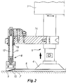
- the removing means 8 of the present invention are secured to suction-pad rods, whereby the removing means automatically follow the movements of the suction-pads, when they are horizontally moved relative to the conveyor carriage.
- This feature has a purpose that both the suction-pads and the removing means can be moved in unison with the correct location when the type of glass (size and shape) is changed.
- the currently available solutions include a flame-effected removal on the one hand and a mechanical removal on the other.
- a flame-effected removal procedure In the flame-effected removal procedure, a marginal zone to be removed is first subjected to a heating flame and the corners are then cut open by sharp cutting flames.
- a drawback in flame-effected removal is a wide marginal zone required thereby, resulting in a large loss of glass.
- Another drawback is that automatization of a plurality of flame stations is complicated in mixed production.
- mechanical removal the opening of corners is effected by means of a cutting knife and it further requires the use of presses for forcing the marginal zone loose.
- a drawback is that two separate removing stations are required and, furthermore, this removing method is also difficult to automatize in mixed production.
- An object of the invention is to provide a method and an apparatus applicable to the removal of a marginal zone in a glass sheet, which make it possible to remove a very narrow marginal zone (5 - 10 mm) and whose operation can be automated in a simple fashion.
- a method and apparatus of the invention can be applied e.g. in the connection of an assembly described in FI Patent application 885048, with publication no. 89039.
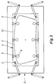
- a conveyor carriage 1 fitted with suction pads 4 is used to carry a glass sheet 6 from an edge-cutting station to a marginal-zone removing station and, after the removal, further to an edge-grinding station.
- a rectangular glass sheet 6 is provided with a cut outline 7, whereby a marginal zone 10 remaining outside said outline is to be removed in an edge-removing station 2.
- said glass sheet 6 is lowered e.g. upon a grid-like base by descending a portion of carriage 1 having suction-pad rods 5 mounted thereon. This is followed by subjecting the four corners of glass sheet 6 to the action of heating flames by means of flame burners 3, the thermal stresses produced thereby removing and crushing said marginal zone 10 external of outline 7.
- the long and narrow marginal zones 10 do not always come loose.
- the removal thereof is secured by means of mechanical removing members 8 which are mounted on rods 5 of suction pads 4 by means of horizontal brackets 14.
- the removing members 8 are spaced a certain horizontal distance from suction pads 4.
- the location of suction pads 4 is adjusted by displacing suction-pad rods 5 in horizontal direction and, thus, said removing members 8 are also automatically carried to a correct location within the boundaries of a marginal zone 10 to be removed.
- a spring 11 urges said removing members 8 downwards.
- a rod 12 is movable through a linear bearing 13, whereby said removing member 8 can be urged upwards against the force of spring 11.
- the cut-off head of a removing member 8 is provided with a bottom surface 9 bevelled to rise from outside towards inside, whereby the removing member 8 does not require exactly precise positioning in lateral direction.
Landscapes
- Chemical & Material Sciences (AREA)
- Engineering & Computer Science (AREA)
- Materials Engineering (AREA)
- Organic Chemistry (AREA)
- Physics & Mathematics (AREA)
- Thermal Sciences (AREA)
- Re-Forming, After-Treatment, Cutting And Transporting Of Glass Products (AREA)
Claims (2)
- Procédé d'enlèvement d'une zone marginale (10) d'une feuille de verre (6) d'une zone intérieure de celle-ci, comprenant les étapes consistant à :
inciser une ligne (7) dans une feuille de verre (6) pour définir une zone intérieure de la feuille de verre située à l'intérieur de la ligne (7), et une zone marginale (10) de la feuille de verre (6) située à l'extérieur de la ligne (7) ;
positionner la feuille de verre (6) sur des moyens formant surface de support de telle sorte que ladite zone intérieure et ladite zone marginale (10) soient toutes deux supportées du dessous par lesdits moyens formant surface de support ;
agencer un chariot de convoyeur (1) portant des ventouses (4) et des moyens mécaniques d'enlèvement de telle sorte que lesdites ventouses (4) adhérent à la zone intérieure de la feuille de verre (6), et qu'une surface inférieure desdits moyens mécaniques d'enlèvement (8) soit en contact avec un bord extérieur de la zone marginale (10), ladite surface inférieure étant biseautée et s'étendant vers le bas afin qu'une extrémité la plus basse de celle-ci soit située vers l'extérieur par rapport à une extrémité la plus à l'intérieur de celle-ci, lesdits moyens d'enlèvement et lesdites ventouses (4) étant capables d'un mouvement relatif vers le haut et vers le bas ;
transporter la feuille de verre (6) au moyen du chariot de convoyeur (1) à ventouses (4) vers une station d'enlèvement de zone marginale ; chauffer la zone marginale (10) au moyen d'un brûleur à flamme (3) pour enlever au moins partiellement la zone marginale (10) de la feuille de verre (6) ; et
soulever ledit chariot (1) pour déplacer lesdites ventouses (4) et la zone intérieure vers le haut par rapport à ladite surface inférieure desdits moyens d'enlèvement (8) de telle manière que ladite surface inférieure empêche le mouvement vers le haut du bord extérieur de la zone marginale (10), entraînant la rupture de la zone marginale (10) le long de ladite ligne (7) et son enlèvement de ladite partie intérieure. - Appareil pour enlever une zone marginale (10) d'une feuille de verre (6), dans lequel la zone marginale (10) est située à l'extérieur d'une ligne incisée dans la feuille de verre (6), comprenant :un chariot de convoyeur (1) pour transporter une feuille de verre vers la station d'enlèvement de zone marginale ;une pluralité de tiges (5) de ventouse montées sur ledit chariot de convoyeur (1) pour se déplacer avec celui-ci ;une pluralité de ventouses (4) montées sur lesdites tiges (5) de ventouse pour être fixées sur la feuille de verre (6) et la transporter ;une pluralité de moyens mécaniques d'enlèvement (8) montés sur les tiges respectives desdites tiges (5) de ventouse, lesdits moyens d'enlèvement (8) et leur tige (5) de ventouse respective étant capables d'un mouvement relatif vers le haut et vers le bas ;lesdits moyens d'enlèvement sont pourvus d'une surface de contact (9) qui est biseautée de telle manière qu'elle s'élève quand on va du bord extérieur des moyens d'enlèvement (8) vers le bord intérieur ;des moyens pour chauffer la zone marginale (10) pour enlever, au moins partiellement, la zone marginale (10) de la feuille de verre (6), par des moyens de chauffage comprenant des brûleurs à flamme (3) ; etdes moyens pour déplacer lesdites tiges (5) de ventouse et les ventouses (4) vers le haut par rapport auxdits moyens mécaniques d'enlèvement (8) de telle manière que le mouvement vers le haut de la zone marginale (10) soit empêché par lesdits moyens mécaniques d'enlèvement (8) pour entraîner l'enlèvement de la zone marginale (10) de la feuille de verre (6) ;lesdites tiges (5) de ventouse étant mobiles horizontalement par rapport audit chariot de convoyeur (1) afin que lesdites ventouses (4) et lesdits moyens mécaniques d'enlèvement (8) puissent être ajustés horizontalement par rapport à la feuille de verre (6).
Applications Claiming Priority (2)
| Application Number | Priority Date | Filing Date | Title |
|---|---|---|---|
| FI892858A FI82677C (fi) | 1989-06-09 | 1989-06-09 | Foerfarande och anordning foer loesgoerning av en utanfoer i en glasskiva skuren konturlinje staoende randzon |
| FI892858 | 1989-06-09 |
Publications (3)
| Publication Number | Publication Date |
|---|---|
| EP0401825A2 EP0401825A2 (fr) | 1990-12-12 |
| EP0401825A3 EP0401825A3 (fr) | 1992-07-22 |
| EP0401825B1 true EP0401825B1 (fr) | 1996-09-11 |
Family
ID=8528618
Family Applications (1)
| Application Number | Title | Priority Date | Filing Date |
|---|---|---|---|
| EP90110812A Expired - Lifetime EP0401825B1 (fr) | 1989-06-09 | 1990-06-07 | Procédé et dispositif pour enlever une zone marginale à l'extérieur d'une ligne incisée dans une feuille de verre |
Country Status (5)
| Country | Link |
|---|---|
| US (2) | US5110340A (fr) |
| EP (1) | EP0401825B1 (fr) |
| JP (1) | JPH0323234A (fr) |
| DE (1) | DE69028446T2 (fr) |
| FI (1) | FI82677C (fr) |
Families Citing this family (14)
| Publication number | Priority date | Publication date | Assignee | Title |
|---|---|---|---|---|
| US5221034A (en) * | 1990-01-31 | 1993-06-22 | Bando Kiko Co., Ltd. | Machine for working a glass plate |
| DE4123929C2 (de) * | 1991-07-19 | 1995-04-06 | Schott Glaswerke | Verfahren und Vorrichtung zum Zerteilen von Flachglastafeln |
| FI103569B (fi) * | 1997-12-17 | 1999-07-30 | Tamglass Ltd Oy | Laite lasilevyyn leikatun ääriviivan ulkopuolisen reunavyöhykkeen irro ttamiseksi |
| WO2000034194A1 (fr) * | 1998-12-09 | 2000-06-15 | Billco Manufacturing, Inc. | Procede et appareil de traitement et de transport de pieces en verre plates |
| KR100622467B1 (ko) * | 2002-06-06 | 2006-09-13 | 카야바 고교 가부시기가이샤 | 전자기 완충기 |
| JP2004217492A (ja) * | 2003-01-17 | 2004-08-05 | Murakami Corp | ガラス板材の切抜方法 |
| IT1401265B1 (it) * | 2010-08-06 | 2013-07-18 | Gallucci | Dispositivo per lo scarico, da un piano di lavoro, di articoli piani nei quali sono ricavate, mediante taglio e/o incisione, porzioni su cui sono riprodotti disegni e/o scritte |
| WO2015048902A1 (fr) * | 2013-10-03 | 2015-04-09 | Bromer Inc. | Dispositif et appareil de découpe de verre par cassage |
| JP6428642B2 (ja) * | 2013-12-27 | 2018-11-28 | Agc株式会社 | 脆性板の加工方法、および脆性板の加工装置 |
| WO2015136946A1 (fr) * | 2014-03-14 | 2015-09-17 | 坂東機工株式会社 | Procédé et dispositif de traitement de plaque de verre |
| JP2016104683A (ja) * | 2014-11-19 | 2016-06-09 | 坂東機工株式会社 | ガラス板の折割方法及びその折割装置 |
| KR102618517B1 (ko) * | 2016-08-17 | 2023-12-28 | 주식회사 탑 엔지니어링 | 스크라이빙 휠의 자동 교체가 가능한 스크라이빙 장치 |
| JP2019107779A (ja) * | 2017-12-15 | 2019-07-04 | 三星ダイヤモンド工業株式会社 | ピックアップユニット |
| KR20220087220A (ko) * | 2020-12-17 | 2022-06-24 | 코닝 인코포레이티드 | 유리기판 히트 챔퍼링 방법 및 장치 |
Family Cites Families (9)
| Publication number | Priority date | Publication date | Assignee | Title |
|---|---|---|---|---|
| US3215345A (en) * | 1963-02-06 | 1965-11-02 | Ferguson Fabrication Co | Apparatus for severing glass articles by thermal shock |
| DE1596352C3 (de) * | 1966-10-18 | 1974-07-04 | Asahi Glass Co. Ltd., Tokio | Vorrichtung zum Abbrechen und Abtransportieren einer Glasplatte von einer sich kontinuierlichen nach oben bewegenden bandförmigen Glastafel |
| US3520457A (en) * | 1968-10-07 | 1970-07-14 | Ford Motor Co | Method of separating pieces of edge trim remaining after the cutting of a glass bracket |
| JPS48102815A (fr) * | 1972-04-10 | 1973-12-24 | ||
| GB1536137A (en) * | 1975-03-06 | 1978-12-20 | Pilkington Brothers Ltd | Methods and apparatus for separating glass sheets into separate sheet portions |
| FR2319589A1 (fr) * | 1975-08-01 | 1977-02-25 | Saint Gobain | Obtention d'un vitrage par brisure, suivant une ligne de decoupe, des bordures d'une plaque de verre |
| DE2945682C2 (de) * | 1979-11-13 | 1982-06-24 | Vereinigte Glaswerke Gmbh, 5100 Aachen | Verfahren und Vorrichtung zum Abbrechen des Randstreifens einer nach einem vorgegebenen Umriß innerhalb eines Glasscheibenrohlings eingeritzten Glasscheibe |
| JPS6278123A (ja) * | 1985-09-30 | 1987-04-10 | Bandou Kiko Kk | 数値制御によるガラス板加工機械 |
| IL84383A (en) * | 1987-11-06 | 1994-08-26 | Kyro Oy | Apparatus for cutting glass blanks |
-
1989
- 1989-06-09 FI FI892858A patent/FI82677C/fi not_active IP Right Cessation
-
1990
- 1990-05-29 US US07/529,664 patent/US5110340A/en not_active Expired - Fee Related
- 1990-06-06 JP JP2148417A patent/JPH0323234A/ja active Pending
- 1990-06-07 EP EP90110812A patent/EP0401825B1/fr not_active Expired - Lifetime
- 1990-06-07 DE DE69028446T patent/DE69028446T2/de not_active Expired - Fee Related
-
1992
- 1992-04-20 US US07/871,115 patent/US5314523A/en not_active Expired - Fee Related
Also Published As
| Publication number | Publication date |
|---|---|
| FI82677B (fi) | 1990-12-31 |
| DE69028446D1 (de) | 1996-10-17 |
| DE69028446T2 (de) | 1997-01-30 |
| EP0401825A3 (fr) | 1992-07-22 |
| FI82677C (fi) | 1994-02-12 |
| FI892858A7 (fi) | 1990-12-10 |
| US5110340A (en) | 1992-05-05 |
| JPH0323234A (ja) | 1991-01-31 |
| EP0401825A2 (fr) | 1990-12-12 |
| US5314523A (en) | 1994-05-24 |
| FI892858A0 (fi) | 1989-06-09 |
Similar Documents
| Publication | Publication Date | Title |
|---|---|---|
| US5314523A (en) | Method for removing a marginal zone external of an outline cut in a glass sheet | |
| CA2354141C (fr) | Procede et appareil de traitement et de transport de pieces en verre plates | |
| US4813993A (en) | Device for forming glass | |
| JP6894844B2 (ja) | ガラス板の曲げ加工用装置 | |
| US4749399A (en) | Ring mold unit for shaping and tempering glass sheet | |
| EP0531153B1 (fr) | Procédé et dispositif de formation de feuilles de verre pliées | |
| CN214991160U (zh) | 一种用于玻璃激光切割裂片一体的装置 | |
| EP0121258A2 (fr) | Façonnage de formes complexes avec des feuilles de verre | |
| KR20130056322A (ko) | 판유리의 절입 절단 장치 | |
| JPWO2014109237A1 (ja) | 強化ガラスの製造方法及び製造装置 | |
| JP3739333B2 (ja) | 板ガラスの割断システム | |
| KR20190126050A (ko) | 판유리의 제조 방법 및 판유리의 스냅핑 장치 | |
| JP4209498B2 (ja) | ガラスの型押し装置 | |
| JP2823642B2 (ja) | 反らせ装置又はその他の熱処理装置に対してガラス板を位置決めする方法並びに装置 | |
| KR102064891B1 (ko) | 취성 재료 기판의 분단 장치 및 그 분단 방법 | |
| CN209615718U (zh) | Pcb板自动曲线分板机 | |
| KR20060059835A (ko) | 위치결정 장치 | |
| CN215940668U (zh) | 一种带有筛选功能的光学影像测量仪 | |
| CN216324437U (zh) | 一种金属板材加工用冲压模具 | |
| KR100838790B1 (ko) | 프레스금형의 소재안착장치 | |
| KR950031949A (ko) | 유리판 벤딩 방법 및 장치 | |
| JPH0583491B2 (fr) | ||
| KR20060075107A (ko) | 유리기판의 절단장치 | |
| JP3429617B2 (ja) | 湾曲ガラス板の成形不良部検出方法および成形支持枠 | |
| CN107324642B (zh) | 玻璃烘弯自重成型模具 |
Legal Events
| Date | Code | Title | Description |
|---|---|---|---|
| PUAI | Public reference made under article 153(3) epc to a published international application that has entered the european phase |
Free format text: ORIGINAL CODE: 0009012 |
|
| AK | Designated contracting states |
Kind code of ref document: A2 Designated state(s): CH DE FR GB IT LI |
|
| PUAL | Search report despatched |
Free format text: ORIGINAL CODE: 0009013 |
|
| AK | Designated contracting states |
Kind code of ref document: A3 Designated state(s): CH DE FR GB IT LI |
|
| 17P | Request for examination filed |
Effective date: 19921204 |
|
| RAP1 | Party data changed (applicant data changed or rights of an application transferred) |
Owner name: TAMGLASS ENGINEERING OY |
|
| 17Q | First examination report despatched |
Effective date: 19940228 |
|
| GRAH | Despatch of communication of intention to grant a patent |
Free format text: ORIGINAL CODE: EPIDOS IGRA |
|
| GRAH | Despatch of communication of intention to grant a patent |
Free format text: ORIGINAL CODE: EPIDOS IGRA |
|
| GRAA | (expected) grant |
Free format text: ORIGINAL CODE: 0009210 |
|
| AK | Designated contracting states |
Kind code of ref document: B1 Designated state(s): CH DE FR GB IT LI |
|
| REG | Reference to a national code |
Ref country code: CH Ref legal event code: NV Representative=s name: DIPL.-ING. HORST QUEHL PATENTANWALT |
|
| ITF | It: translation for a ep patent filed | ||
| REF | Corresponds to: |
Ref document number: 69028446 Country of ref document: DE Date of ref document: 19961017 |
|
| ET | Fr: translation filed | ||
| PLBE | No opposition filed within time limit |
Free format text: ORIGINAL CODE: 0009261 |
|
| STAA | Information on the status of an ep patent application or granted ep patent |
Free format text: STATUS: NO OPPOSITION FILED WITHIN TIME LIMIT |
|
| 26N | No opposition filed | ||
| PGFP | Annual fee paid to national office [announced via postgrant information from national office to epo] |
Ref country code: FR Payment date: 20000518 Year of fee payment: 11 |
|
| PGFP | Annual fee paid to national office [announced via postgrant information from national office to epo] |
Ref country code: GB Payment date: 20000523 Year of fee payment: 11 |
|
| PG25 | Lapsed in a contracting state [announced via postgrant information from national office to epo] |
Ref country code: GB Free format text: LAPSE BECAUSE OF NON-PAYMENT OF DUE FEES Effective date: 20010607 |
|
| GBPC | Gb: european patent ceased through non-payment of renewal fee |
Effective date: 20010607 |
|
| PG25 | Lapsed in a contracting state [announced via postgrant information from national office to epo] |
Ref country code: FR Free format text: LAPSE BECAUSE OF NON-PAYMENT OF DUE FEES Effective date: 20020228 |
|
| PGFP | Annual fee paid to national office [announced via postgrant information from national office to epo] |
Ref country code: CH Payment date: 20020521 Year of fee payment: 13 |
|
| PGFP | Annual fee paid to national office [announced via postgrant information from national office to epo] |
Ref country code: DE Payment date: 20020523 Year of fee payment: 13 |
|
| PG25 | Lapsed in a contracting state [announced via postgrant information from national office to epo] |
Ref country code: LI Free format text: LAPSE BECAUSE OF NON-PAYMENT OF DUE FEES Effective date: 20030630 Ref country code: CH Free format text: LAPSE BECAUSE OF NON-PAYMENT OF DUE FEES Effective date: 20030630 |
|
| PG25 | Lapsed in a contracting state [announced via postgrant information from national office to epo] |
Ref country code: DE Free format text: LAPSE BECAUSE OF NON-PAYMENT OF DUE FEES Effective date: 20040101 |
|
| REG | Reference to a national code |
Ref country code: CH Ref legal event code: PL |
|
| PG25 | Lapsed in a contracting state [announced via postgrant information from national office to epo] |
Ref country code: IT Free format text: LAPSE BECAUSE OF NON-PAYMENT OF DUE FEES;WARNING: LAPSES OF ITALIAN PATENTS WITH EFFECTIVE DATE BEFORE 2007 MAY HAVE OCCURRED AT ANY TIME BEFORE 2007. THE CORRECT EFFECTIVE DATE MAY BE DIFFERENT FROM THE ONE RECORDED. Effective date: 20050607 |