EP0401910A1 - Prothèse de jambe universelle - Google Patents
Prothèse de jambe universelle Download PDFInfo
- Publication number
- EP0401910A1 EP0401910A1 EP90201399A EP90201399A EP0401910A1 EP 0401910 A1 EP0401910 A1 EP 0401910A1 EP 90201399 A EP90201399 A EP 90201399A EP 90201399 A EP90201399 A EP 90201399A EP 0401910 A1 EP0401910 A1 EP 0401910A1
- Authority
- EP
- European Patent Office
- Prior art keywords
- sheath
- prosthesis
- leg prosthesis
- universal
- universal leg
- Prior art date
- Legal status (The legal status is an assumption and is not a legal conclusion. Google has not performed a legal analysis and makes no representation as to the accuracy of the status listed.)
- Withdrawn
Links
Images

Classifications
-
- A—HUMAN NECESSITIES
- A61—MEDICAL OR VETERINARY SCIENCE; HYGIENE
- A61F—FILTERS IMPLANTABLE INTO BLOOD VESSELS; PROSTHESES; DEVICES PROVIDING PATENCY TO, OR PREVENTING COLLAPSING OF, TUBULAR STRUCTURES OF THE BODY, e.g. STENTS; ORTHOPAEDIC, NURSING OR CONTRACEPTIVE DEVICES; FOMENTATION; TREATMENT OR PROTECTION OF EYES OR EARS; BANDAGES, DRESSINGS OR ABSORBENT PADS; FIRST-AID KITS
- A61F2/00—Filters implantable into blood vessels; Prostheses, i.e. artificial substitutes or replacements for parts of the body; Appliances for connecting them with the body; Devices providing patency to, or preventing collapsing of, tubular structures of the body, e.g. stents
- A61F2/50—Prostheses not implantable in the body
- A61F2/78—Means for protecting prostheses or for attaching them to the body, e.g. bandages, harnesses, straps, or stockings for the limb stump
- A61F2/80—Sockets, e.g. of suction type
-
- A—HUMAN NECESSITIES
- A61—MEDICAL OR VETERINARY SCIENCE; HYGIENE
- A61F—FILTERS IMPLANTABLE INTO BLOOD VESSELS; PROSTHESES; DEVICES PROVIDING PATENCY TO, OR PREVENTING COLLAPSING OF, TUBULAR STRUCTURES OF THE BODY, e.g. STENTS; ORTHOPAEDIC, NURSING OR CONTRACEPTIVE DEVICES; FOMENTATION; TREATMENT OR PROTECTION OF EYES OR EARS; BANDAGES, DRESSINGS OR ABSORBENT PADS; FIRST-AID KITS
- A61F2/00—Filters implantable into blood vessels; Prostheses, i.e. artificial substitutes or replacements for parts of the body; Appliances for connecting them with the body; Devices providing patency to, or preventing collapsing of, tubular structures of the body, e.g. stents
- A61F2/50—Prostheses not implantable in the body
- A61F2/60—Artificial legs or feet or parts thereof
Definitions
- the invention relates to a universal leg prosthesis comprising: a longitudinally stiff sheath-like body open on one side, the edge of which on the open side is bent outward over a portion of the periphery; a tubular body adjustable in lengthwise direction fixed on the closed side of the sheath-like body approximately in the line of the longitudinal axis of that body; and a treading body fixed on the free outer end of the tubular body.
- a problem which occurs here, however, is that a leg stump only assumes its definitive form several months after the amputation. Use is therefore generally made of training or interim prostheses in the period between the moment of amputation and the provision of a permanent prosthesis.
- training prostheses There are two sorts of training prostheses, namely the individually manufactured training prosthesis and the training prosthesis for universal use.
- the portion of the prosthesis in which the leg stump is received is made to size for the patient from a simply deformable material, such as for instance plaster or a plastic.
- the portion of the prosthesis in which the leg stump is received is provided with means whereby this portion can be simply adapted to the dimensions of the leg stumps of the various users.
- a great problem with universally applicable training prostheses is usually the fit of the prosthesis.
- the leg prosthesis In order to be worn comfortably the leg prosthesis must namely preferably be supported, just as in the case of a leg, on parts of the body which are suitable for withstanding heavy loadings for long periods, such as parts of the skeleton and some tendons.
- the ischial tuberosity (tuber ischiadicum) is preferably chosen as a suitable body part for the support, whereto most upper leg prostheses are provided at the top with an edge bent over through a part of the periphery, the so-called tuberosity ridge.
- Lower leg prostheses usually support on the knee cap (patella tendon) or, when the stump is too short to fix the lower leg prosthesis optimally thereon, it is supported by means of a thigh corset on the upper leg, while prostheses for amputations through the knee joint (the so-called knee exarticulations) are usually supported on the extremity of the upper leg.
- the present invention therefore has for its object to provide a universally applicable leg prosthesis which can be well supported under all conditions because it directly engages the ischial tuberosity, and wherein the heretofore mentioned drawbacks are avoided.
- the sheath-like body of the universal leg prosthesis is provided on the inside with means for fastening the leg stump against the side of the body situated in the line of the bent over edge.
- the means for fixing the leg stump consist of straps attached to the inside of the sheath-like body that are continuously adjustable in lengthwise direction and the outer ends of which are situated outside the sheath-like body. These straps are preferably relatively stiff in order to distribute the fixing forces as well as possible over the surface of the leg tissue and to facilitate fitting of the prosthesis. These straps are preferably provided at the ends with Velcro tape.
- the treading body is a foot prosthesis.
- the sheath-like body is provided with a slit beginning at the open side and running along a large portion of the length of the body, whereby the sheath-like body can be bent open to facilitate putting on and taking off the prosthesis, and with fastening means bridging the slit wherewith the sheath can be closed again after being put on. Provisions are preferably arranged on the sheath-like body for attaching a shoulder strap.
- the tubular body on the outer end of the prosthesis is preferably continuously adjustable in lengthwise direction.
- Figure 1 shows a sheath-like body 1 open on one side, of which the edge 2 on the open side is bent outward over a part of the periphery, whereby a so-called tuberosity ridge is formed.
- the sheath-like body 1 is provided on the closed side with a longitudinally adjustable tubular body 3 attached approximately in the line of the axis of the body, and on the free end of which is fixed a treading body 4.
- the sheath-like body 1 is provided on the inside with means 5 for fastening a leg stump 6 against the side of the body lying in the line of the tuberosity ridge.
- fastening means 5 run from the point where they are fastened to the sheath-like body 1 along a large portion of the peripheral direction of the body and on the interior thereof, to finally leave the body through slots 16.
- the fastening means 5 are provided with Velcro tape on their free outer ends 7 on the side facing the sheath-like body 1.
- the fastening means 5 are provided with Velcro tape along a portion of their length lying outside the sheath-like body 1 on the side facing away from the sheath-like body 1.
- the sheath-like body 1 is provided over a portion of its length with a slit 8 which, when the prosthesis is in use, is closed by fastening means 9 bridging the slit.
- the fastening means 9 comprise a strap, which on one side of the slit 8 is fixed onto the sheath-like body 1, and the free end of which, which is provided on the side facing the sheath-like body 1 with Velcro tape, can be fastened to a strip of Velcro tape 17 fixed onto the sheath-like body 1.
- the outer ends of the fastening means 5 and 9 are loosened, and the sheath like body 1 is bent out slightly whereby step-in is facilitated.
- the outer ends of the fastening means 5 are then guided into the sheath-like body 1 until the fastening means 5 lie precisely against the inner wall thereof, whereby step-in is further facilitated, and are temporarily fixed in place.
- the leg stump 6 is positioned in the sheath such that the patient's ischial tuberosity 19 rests precisely on the bent over portion of the edge 2 of the sheath-like body 1, the so-called tuberosity ridge. This optimal position of the prosthesis is indicated in figure 1 by a dashed-dotted line.
- FIG 2 the sheath-like body 1 is shown with the fastening means 5 arranged therein.
- the outer ends 20 of the fastening means 5 are fixed on one side of the bent over portion of the edge 2 to the sheath-like body 1, from where the fastening means 5 are guided along the side of the sheath-like body 1 lying opposite the bent over portion of the edge 2 to the slots 16, through which they leave the sheath-like body 1.
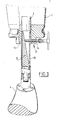
- FIG. 3 shows the tubular body 3, which is provided with an adjusting mechanism 12, with which the total length of the prosthesis can be varied.
- the adjusting mechanism 12 comprises a socket 13 mounted on the underside of the sheath-like body 1, in which the tubular body 3 can move up and down, and wherein likewise an adjustable screw bolt 14 is arranged.
- an adjustable screw bolt 14 is arranged through a slot 18 arranged in the wall of the tubular body 3 the screw bolt 14 engages a wedge-shaped part 15, the thickest end part of which is situated on the side of the treading body 4.
- the length of the prosthesis can be varied by loosening the screw bolt 14, moving the tubular body 3 in the socket 13 upward or downward until the desired position is reached and subsequently tightening the screw bolt 14 again.
- the prosthesis will only undergo a slight shortening when loaded in the case the screw bolt 14 unexpectedly become slightly loose.
Landscapes
- Health & Medical Sciences (AREA)
- Transplantation (AREA)
- Heart & Thoracic Surgery (AREA)
- Oral & Maxillofacial Surgery (AREA)
- Engineering & Computer Science (AREA)
- Biomedical Technology (AREA)
- Cardiology (AREA)
- Vascular Medicine (AREA)
- Life Sciences & Earth Sciences (AREA)
- Animal Behavior & Ethology (AREA)
- General Health & Medical Sciences (AREA)
- Public Health (AREA)
- Veterinary Medicine (AREA)
- Orthopedic Medicine & Surgery (AREA)
- Prostheses (AREA)
Applications Claiming Priority (2)
| Application Number | Priority Date | Filing Date | Title |
|---|---|---|---|
| NL8901357A NL8901357A (nl) | 1989-05-29 | 1989-05-29 | Universele beenprothese. |
| NL8901357 | 1989-05-29 |
Publications (1)
| Publication Number | Publication Date |
|---|---|
| EP0401910A1 true EP0401910A1 (fr) | 1990-12-12 |
Family
ID=19854736
Family Applications (1)
| Application Number | Title | Priority Date | Filing Date |
|---|---|---|---|
| EP90201399A Withdrawn EP0401910A1 (fr) | 1989-05-29 | 1990-05-29 | Prothèse de jambe universelle |
Country Status (2)
| Country | Link |
|---|---|
| EP (1) | EP0401910A1 (fr) |
| NL (1) | NL8901357A (fr) |
Cited By (2)
| Publication number | Priority date | Publication date | Assignee | Title |
|---|---|---|---|---|
| DE4325444C1 (de) * | 1993-07-29 | 1995-04-13 | Felix Carstens | Künstliches Glied |
| WO2017191120A1 (fr) * | 2016-05-02 | 2017-11-09 | Otto Bock Healthcare Gmbh | Dispositif orthopédique |
Citations (6)
| Publication number | Priority date | Publication date | Assignee | Title |
|---|---|---|---|---|
| DE314499C (fr) * | ||||
| FR482766A (fr) * | 1916-09-01 | 1917-04-26 | Ingvard Svindt | Procédé de fabrication de jambes artificielles |
| GB109085A (en) * | 1916-08-29 | 1917-08-29 | Adjustable Artificial Limb Co Inc | Improvements in Artificial Limbs. |
| GB127451A (en) * | 1918-07-30 | 1919-06-05 | Frederick Charles Lynde | Improvements in Artificial Limbs and the like. |
| GB2103490A (en) * | 1981-08-14 | 1983-02-23 | Blatchford & Sons Ltd | Artificial limb socket |
| US4842608A (en) * | 1988-01-27 | 1989-06-27 | Ortho-Bionics Laboratory, Inc. | Fluctuating volume adjustable preparatory below knee prosthetic socket |
-
1989
- 1989-05-29 NL NL8901357A patent/NL8901357A/nl not_active Application Discontinuation
-
1990
- 1990-05-29 EP EP90201399A patent/EP0401910A1/fr not_active Withdrawn
Patent Citations (6)
| Publication number | Priority date | Publication date | Assignee | Title |
|---|---|---|---|---|
| DE314499C (fr) * | ||||
| GB109085A (en) * | 1916-08-29 | 1917-08-29 | Adjustable Artificial Limb Co Inc | Improvements in Artificial Limbs. |
| FR482766A (fr) * | 1916-09-01 | 1917-04-26 | Ingvard Svindt | Procédé de fabrication de jambes artificielles |
| GB127451A (en) * | 1918-07-30 | 1919-06-05 | Frederick Charles Lynde | Improvements in Artificial Limbs and the like. |
| GB2103490A (en) * | 1981-08-14 | 1983-02-23 | Blatchford & Sons Ltd | Artificial limb socket |
| US4842608A (en) * | 1988-01-27 | 1989-06-27 | Ortho-Bionics Laboratory, Inc. | Fluctuating volume adjustable preparatory below knee prosthetic socket |
Cited By (4)
| Publication number | Priority date | Publication date | Assignee | Title |
|---|---|---|---|---|
| DE4325444C1 (de) * | 1993-07-29 | 1995-04-13 | Felix Carstens | Künstliches Glied |
| WO2017191120A1 (fr) * | 2016-05-02 | 2017-11-09 | Otto Bock Healthcare Gmbh | Dispositif orthopédique |
| EP3451977A1 (fr) * | 2016-05-02 | 2019-03-13 | Ottobock SE & Co. KGaA | Dispositif orthopédique |
| EP3451977B1 (fr) * | 2016-05-02 | 2025-11-19 | Ottobock SE & Co. KGaA | Dispositif orthopédique |
Also Published As
| Publication number | Publication date |
|---|---|
| NL8901357A (nl) | 1990-12-17 |
Similar Documents
| Publication | Publication Date | Title |
|---|---|---|
| US5728165A (en) | Adjustable post-operative preparatory prosthetic system | |
| US5651792A (en) | Flexible lower limb prosthetic assembly with removable dressing | |
| EP1620046B1 (fr) | Systeme d'ancrage de prothese a fixation fiable | |
| US4908037A (en) | Suspension prosthetic sleeve for rigorous activity | |
| US6991657B1 (en) | Adjustable prosthetic socket | |
| US4128903A (en) | Temporary walking aid for use after lower leg amputations | |
| US20040158332A1 (en) | Prosthesis | |
| CA2312832A1 (fr) | Orthese pedi-jambiere | |
| SE420048B (sv) | Anordning for anbringning av en ben- eller armprotes pa en amputationsstump | |
| CA2001287A1 (fr) | Attelle de la cheville | |
| EP1216670A3 (fr) | Membre artificiel avec emboíture anatomique | |
| CA2326678A1 (fr) | Appareillage du type bequille | |
| CA2470182A1 (fr) | Support de cheville | |
| US4483336A (en) | Universal suspensory leg cast and splint support | |
| GB2241440B (en) | A lower limb prosthesis and an artificial foot for a lower limb prosthesis | |
| EP0401910A1 (fr) | Prothèse de jambe universelle | |
| GB2228201A (en) | A self-suspending prosthesis for a long below-knee stump | |
| US5911696A (en) | Integral strap handling device for a leg cast | |
| US5419755A (en) | Weight bearing brace for femur and hip joint | |
| EP0195186A2 (fr) | Orthèse pour stabilisation | |
| US7288118B1 (en) | Quadriceps control device for prosthetics/orthotics | |
| SU1703090A1 (ru) | Крепление протеза голени | |
| SU957893A1 (ru) | Протез голени | |
| RU2076669C1 (ru) | Металлический протез голени | |
| Ruder et al. | Techniques of lower limb prosthetic manufacture using Lightcast II |
Legal Events
| Date | Code | Title | Description |
|---|---|---|---|
| PUAI | Public reference made under article 153(3) epc to a published international application that has entered the european phase |
Free format text: ORIGINAL CODE: 0009012 |
|
| AK | Designated contracting states |
Kind code of ref document: A1 Designated state(s): AT BE CH DE DK ES FR GB GR IT LI LU NL SE |
|
| STAA | Information on the status of an ep patent application or granted ep patent |
Free format text: STATUS: THE APPLICATION IS DEEMED TO BE WITHDRAWN |
|
| 18D | Application deemed to be withdrawn |
Effective date: 19910613 |