EP0401933B1 - Video-Signalempfangs- und -verarbeitungssystem - Google Patents
Video-Signalempfangs- und -verarbeitungssystem Download PDFInfo
- Publication number
- EP0401933B1 EP0401933B1 EP90201434A EP90201434A EP0401933B1 EP 0401933 B1 EP0401933 B1 EP 0401933B1 EP 90201434 A EP90201434 A EP 90201434A EP 90201434 A EP90201434 A EP 90201434A EP 0401933 B1 EP0401933 B1 EP 0401933B1
- Authority
- EP
- European Patent Office
- Prior art keywords
- signal
- video signal
- signal component
- component
- components
- Prior art date
- Legal status (The legal status is an assumption and is not a legal conclusion. Google has not performed a legal analysis and makes no representation as to the accuracy of the status listed.)
- Expired - Lifetime
Links
- 230000005540 biological transmission Effects 0.000 abstract description 15
- 230000008054 signal transmission Effects 0.000 abstract description 3
- 230000002457 bidirectional effect Effects 0.000 description 2
- 239000002131 composite material Substances 0.000 description 2
- 238000000034 method Methods 0.000 description 1
Images
Classifications
-
- H—ELECTRICITY
- H04—ELECTRIC COMMUNICATION TECHNIQUE
- H04N—PICTORIAL COMMUNICATION, e.g. TELEVISION
- H04N5/00—Details of television systems
- H04N5/76—Television signal recording
- H04N5/765—Interface circuits between an apparatus for recording and another apparatus
-
- H—ELECTRICITY
- H04—ELECTRIC COMMUNICATION TECHNIQUE
- H04N—PICTORIAL COMMUNICATION, e.g. TELEVISION
- H04N11/00—Colour television systems
Definitions
- the invention relates to a device for receiving a video signal including a luminance signal component and a chrominance signal component, which device has an input for the video signal.
- the invention also relates to a device for processing a video signal including a luminance signal component and a chrominance signal component, which device has an input and an output for the video signal.
- a video signal transmission system comprising a transmission device, and a receiver is described in Funktechnik 38 (1983), Vol. 5, pp. 208-212 in which the technique known as SCART connection for transmitting signals between a television receiver and external video apparatuses is described.
- the above-mentioned video signal processing device is constituted by a television receiver or a video recorder which can receive the video signal from another device as well as supply this signal to the device.
- a device for receiving a video signal including a luminance signal component and a chrominance signal component which device has an input for the video signal, a further input for one of said signal components and a signal combination circuit for obtaining the other one of said signal components, is known from IEEE Trans. on CE, 1988 Int. Conf. on CE, Part 1, Vol. 34, No. 3, August 1988. This known device requires two input terminals for receiving separate chrominance and luminance components and a separate third terminal for receiving a composite video signal.
- the receiving device described above is characterized in that the first mentioned input and the further input are coupled to corresponding inputs of the signal combination circuit so as to obtain the other one of said signal components from the video signal and the one of said signal components.
- the device for processing the video signal including a luminance signal component and a chrominance signal component, which device has an input and an output for the video signal, a further input for one of said signal components, a signal combination circuit for obtaining the other one of said signal components, and a further output for the one of said signal components, is characterized in that the first mentioned input and the further input are coupled to corresponding inputs of the signal combination circuit so as to obtain the other one of said signal components from the video signal and the one of said signal components.
- the invention is based on the recognition that the signal component which is not transmitted can be obtained in a very simple manner from the video signal and the transmitted signal component by means of a subtractor circuit in the receiving device according to the invention, if not only the video signal but also one of the said signal components is transmitted by the transmission device according to the invention.
- the one, transmitted signal component may be either the luminance signal component or the chrominance signal component.
- the chrominance signal component is preferred for the following reason.
- amplitude and delay time differences will arise between the video signal and the one signal component, so that crosstalk errors of the signal component which has been transmitted on the component which has not been transmitted will be produced when regaining the signal component which has not been transmitted.
- cross-luminance errors errors in the luminance signal component due to crosstalk of the chrominance signal component
- cross-color errors errors in the chrominance signal component due to crosstalk of the luminance signal component
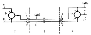
- a luminance signal component Y and a chrominance signal component C are added to obtain a video signal CVBS by an adder 1, which signal is applied to a first output 3 of the transmission device T.
- the chrominance signal component C is applied to a second output 5 of the transmission device T.
- a transmission lead L shown in the centre comprises a first lead for the video signal CVBS and a second lead for the chrominance signal component C.
- the first lead connects the output 3 of the transmission device T to a first input 7 of a receiving device R.
- the second lead connects the output 5 of the transmission device T to a second input 9 of the receiving device R.
- the video signal CVBS and the chrominance signal C are applied to a subtractor 11 for obtaining the luminance signal component Y which has not been transmitted from these transmitted signals.
- a video signal processing device which must be able to receive and supply a video signal can be composed in a simple manner by means of the transmission device T and the receiving device R and is therefore not shown separately.
- the (bidirectional) transmission lead comprises a lead pair for the video signal CVBS and a further lead pair for the chrominance signal component C.
Landscapes
- Engineering & Computer Science (AREA)
- Multimedia (AREA)
- Signal Processing (AREA)
- Color Television Systems (AREA)
- Processing Of Color Television Signals (AREA)
- Radio Transmission System (AREA)
- Two-Way Televisions, Distribution Of Moving Picture Or The Like (AREA)
- Radar Systems Or Details Thereof (AREA)
Claims (4)
- Anordnung zum Empfangen eines Videosignals mit einer Leuchtdichtesignalkomponente und einer Farbartsignalkomponente, und diese Anordnung enthält einen Eingang für das Videosignal, einen weiteren Eingang für eine der Signalkomponenten und eine Signalverknüpfungsschaltung zum Erhalten der anderen der Signalkomponenten, dadurch gekennzeichnet, daß der erstgenannte Eingang und der weitere Eingang mit entsprechenden Eingängen der Signalverknüpfungsschaltung gekoppelt sind, um die andere der Signalkomponenten aus dem Videosignal und die eine der Signalkomponenten zu erhalten.
- Empfangsanordnung nach Anspruch 1, in der die eine der Signalkomponenten die Farbartsignalkomponente ist.
- Anordnung zum Verarbeiten eines Videosignals mit einer Leuchtdichtesignalkomponente und einer Farbartsignalkomponente, wobei die Anordnung einen Eingang und einen Ausgang für das Videosignal, einen weiteren Eingang für eine der Signalkomponenten, eine Signalverknüpfungseinheit zum Erhalten der anderen der Signalkomponenten, und einen weiteren Ausgang für die eine der Signalkomponenten enthält, dadurch gekennzeichnet, daß der erstgenannte Eingang und der weitere Eingang mit entsprechenden Eingängen der Signalverknüpfungsschaltung gekoppelt sind, um die andere der Signalkomponenten aus dem Videosignal und die eine der Signalkomponenten zu erhalten.
- Videosignalverarbeitungsanordnung nach Anspruch 3,worin die eine der Signalkomponenten die Farbartsignalkomponente ist.
Applications Claiming Priority (2)
| Application Number | Priority Date | Filing Date | Title |
|---|---|---|---|
| NL8901472 | 1989-06-09 | ||
| NL8901472A NL8901472A (nl) | 1989-06-09 | 1989-06-09 | Videosignaaloverdrachtssysteem. |
Publications (2)
| Publication Number | Publication Date |
|---|---|
| EP0401933A1 EP0401933A1 (de) | 1990-12-12 |
| EP0401933B1 true EP0401933B1 (de) | 1994-08-31 |
Family
ID=19854808
Family Applications (1)
| Application Number | Title | Priority Date | Filing Date |
|---|---|---|---|
| EP90201434A Expired - Lifetime EP0401933B1 (de) | 1989-06-09 | 1990-06-05 | Video-Signalempfangs- und -verarbeitungssystem |
Country Status (5)
| Country | Link |
|---|---|
| EP (1) | EP0401933B1 (de) |
| JP (1) | JPH0326190A (de) |
| AT (1) | ATE110915T1 (de) |
| DE (1) | DE69011962T2 (de) |
| NL (1) | NL8901472A (de) |
Families Citing this family (1)
| Publication number | Priority date | Publication date | Assignee | Title |
|---|---|---|---|---|
| DE502005010654D1 (de) | 2005-09-07 | 2011-01-20 | Modine Mfg Co | Wärmetauscher |
Family Cites Families (1)
| Publication number | Priority date | Publication date | Assignee | Title |
|---|---|---|---|---|
| US4660073A (en) * | 1984-12-18 | 1987-04-21 | Eastman Kodak Company | Video apparatus for selectively processing either composite or component color video signals |
-
1989
- 1989-06-09 NL NL8901472A patent/NL8901472A/nl not_active Application Discontinuation
-
1990
- 1990-06-05 AT AT90201434T patent/ATE110915T1/de not_active IP Right Cessation
- 1990-06-05 DE DE69011962T patent/DE69011962T2/de not_active Expired - Fee Related
- 1990-06-05 EP EP90201434A patent/EP0401933B1/de not_active Expired - Lifetime
- 1990-06-06 JP JP2146377A patent/JPH0326190A/ja active Pending
Also Published As
| Publication number | Publication date |
|---|---|
| DE69011962D1 (de) | 1994-10-06 |
| NL8901472A (nl) | 1991-01-02 |
| DE69011962T2 (de) | 1995-03-30 |
| EP0401933A1 (de) | 1990-12-12 |
| ATE110915T1 (de) | 1994-09-15 |
| JPH0326190A (ja) | 1991-02-04 |
Similar Documents
| Publication | Publication Date | Title |
|---|---|---|
| CA1062361A (en) | Chrominance-luninance separator | |
| GB1515551A (en) | Noise reduction in electrical signals | |
| EP0392552B9 (de) | Tonumschaltung für ein Ton/Videosystem mit S-Videofähigkeit | |
| US2993086A (en) | Color television system | |
| US4855815A (en) | Digital composite color video signal separating circuit with vertical correlation weighting function | |
| JP2556368B2 (ja) | ビデオ信号処理装置 | |
| GB1398636A (en) | Colour television system | |
| US4695877A (en) | Video signal processing apparatus for compensating for time differences between luminance and chrominance signals of a PAL system | |
| CA2002555A1 (en) | Television receiver | |
| KR880004695A (ko) | 컬러영상신호의 전송방법, 표시장치및 처리장치 | |
| US5389975A (en) | Video additive information identifying device with plural inputs | |
| EP0241935B1 (de) | Schaltungen zur Verarbeitung eines Farbvideosignales | |
| EP0401933A1 (de) | Video-Signalempfangs- und -verarbeitungssystem | |
| GB2009546A (en) | Television receiver IF and detector arrangement | |
| KR930010356B1 (ko) | 동적응재생회로 | |
| GB2134743A (en) | Color display system | |
| EP0334351A3 (de) | Schaltung zur Verarbeitung eines Videosignals und eine Einfügungsschaltung dafür | |
| KR0141679B1 (ko) | 디지탈 콤필터의 고역 보상회로 | |
| KR960007568B1 (ko) | 위성방송 수신기의 디코더용 콘넥터를 비디오 카세트 레코더와 공용하기 위한 스위칭 회로 | |
| KR200272078Y1 (ko) | 일체형 영상 입출력장치 | |
| KR890006337Y1 (ko) | 비데오, 카메라의 색신호 라인 페어링 방지회로 | |
| JPS5851716B2 (ja) | 画像伝送方式 | |
| KR940001861Y1 (ko) | Pal/secam 겸용 tv의 휘도 신호 휠터 회로 | |
| KR100257268B1 (ko) | 입출력 공용단자의 분리 적용회로 | |
| JPS62272797A (ja) | カラ−映像信号記録再生装置 |
Legal Events
| Date | Code | Title | Description |
|---|---|---|---|
| PUAI | Public reference made under article 153(3) epc to a published international application that has entered the european phase |
Free format text: ORIGINAL CODE: 0009012 |
|
| AK | Designated contracting states |
Kind code of ref document: A1 Designated state(s): AT DE FR GB |
|
| 17P | Request for examination filed |
Effective date: 19910606 |
|
| 17Q | First examination report despatched |
Effective date: 19930524 |
|
| GRAA | (expected) grant |
Free format text: ORIGINAL CODE: 0009210 |
|
| AK | Designated contracting states |
Kind code of ref document: B1 Designated state(s): AT DE FR GB |
|
| PG25 | Lapsed in a contracting state [announced via postgrant information from national office to epo] |
Ref country code: AT Effective date: 19940831 |
|
| REF | Corresponds to: |
Ref document number: 110915 Country of ref document: AT Date of ref document: 19940915 Kind code of ref document: T |
|
| REF | Corresponds to: |
Ref document number: 69011962 Country of ref document: DE Date of ref document: 19941006 |
|
| ET | Fr: translation filed | ||
| PG25 | Lapsed in a contracting state [announced via postgrant information from national office to epo] |
Ref country code: GB Effective date: 19950605 |
|
| PLBE | No opposition filed within time limit |
Free format text: ORIGINAL CODE: 0009261 |
|
| STAA | Information on the status of an ep patent application or granted ep patent |
Free format text: STATUS: NO OPPOSITION FILED WITHIN TIME LIMIT |
|
| 26N | No opposition filed | ||
| GBPC | Gb: european patent ceased through non-payment of renewal fee |
Effective date: 19950605 |
|
| PG25 | Lapsed in a contracting state [announced via postgrant information from national office to epo] |
Ref country code: FR Effective date: 19960229 |
|
| PG25 | Lapsed in a contracting state [announced via postgrant information from national office to epo] |
Ref country code: DE Effective date: 19960301 |
|
| REG | Reference to a national code |
Ref country code: FR Ref legal event code: ST |