EP0401974A2 - Funkübertragungssystem mit einer Frequenz - Google Patents
Funkübertragungssystem mit einer Frequenz Download PDFInfo
- Publication number
- EP0401974A2 EP0401974A2 EP90304884A EP90304884A EP0401974A2 EP 0401974 A2 EP0401974 A2 EP 0401974A2 EP 90304884 A EP90304884 A EP 90304884A EP 90304884 A EP90304884 A EP 90304884A EP 0401974 A2 EP0401974 A2 EP 0401974A2
- Authority
- EP
- European Patent Office
- Prior art keywords
- repeater
- message
- repeaters
- receiver
- radio transmission
- Prior art date
- Legal status (The legal status is an assumption and is not a legal conclusion. Google has not performed a legal analysis and makes no representation as to the accuracy of the status listed.)
- Granted
Links
Images

Classifications
-
- H—ELECTRICITY
- H04—ELECTRIC COMMUNICATION TECHNIQUE
- H04B—TRANSMISSION
- H04B7/00—Radio transmission systems, i.e. using radiation field
- H04B7/14—Relay systems
- H04B7/15—Active relay systems
- H04B7/155—Ground-based stations
Definitions
- the present invention relates to a radio transmission system in which messages sent by a transmitter are picked up by a central receiver via a number of repeaters.
- the invention is particularly concerned with low power radio transmissions using a single frequency, since low power radio transmitters and their associated receivers are licence-exempt, provided that they operate on a single defined channel (which may be in the HF, VHF or UHF band), the transmitter output power is restricted to a low level, and the radio system operates on a single site.
- Such low power, licence-exempt devices are commonly used to send binary data messages for various purposes, such as telemetry, telecontrol and telecommand applications, for indentification tagging and increasingly for "in-building” and “on-site” wireless security systems.
- the present invention seeks to overcome this difficulty, whilst retaining the advantage of greater operational range resulting from the use of repeaters.
- a radio transmission system designed to operate on a single defined frequency channel, the system comprising a central receiver, at least one transmitter remote from the central receiver and, located between said receiver and transmitter, a plurality of repeaters each adapted to receive a message from a transmitter or from another repeater and to re-transmit said message to the receiver either directly or via at least one other repeater, in which the system includes protection means associated with the repeaters for protecting said message against loss or corruption during transmission of said message from said transmitter to said receiver.
- the protection means comprises means for preventing simultaneous transmission of said message by two or more repeaters.
- each repeater includes delay means for imposing a time delay between receipt of said message by said repeater and re-transmission of said message by said repeater, the time delay associated with each repeater being unique to that repeater.
- each repeater prevents a message received by more than one repeater from being re-transmitted exactly simultaneously, thereby avoiding loss of the message due to traffic contention.
- the unique time delay can be pre-set using data in a further electronic memory of the repeater, or alternatively using switches or potentiometers.
- the repeaters are arranged in zones around the central receiver, each repeater including the zone address number such that the repeaters closest to the central receiver are designated "zone 1", and those furthest away from the central receiver have the highest zone number.
- a transmitter when a transmitter sends a message, it is received by one or more repeaters and/or the central receiver.
- the message is stored in the repeater for the unique time delay, and the zone number information of that repeater is added to the message, which is then re-transmitted.
- This re-transmitted message (including the zone number information) is received by one or more repeaters and/or the central receiver, but a repeater with a zone number equal to or greater than that in the received message does not process the message further.
- Any repeater with a lower zone number overwrites the zone number information in the message with its own zone number and re-transmits the message after its own pre-set unique time delay.
- each repeater has a unique identification address, memory means storing a list of identification addresses relating to those repeaters within its range and control means operative to cause the repeater to re-transmit said message to a first identification address on said list and, in the event that said re-transmitted message is not received or is incorrectly received by the first addressed repeater, to re-transmit said message again, but to a second identification address on said list.
- the address list would be arranged in order of proximity to the central receiver, i.e. the addresses of those repeaters closest to the central receiver are at the top of the list.
- control means directs the re-transmitted message first to the repeater address at the top of the list, monitors the channel until it receives the message repeated by the addressed repeater, and, in the event that it does not receive the message which should have been repeated by the addressed repeater, redirects the message to the second address on the list, and so on until the addressing repeater finally receives confirmation that its message has been received.
- This system of "intelligent" repeaters may be used in conjunction with the pre-set time delay and/or interrogation means provided in the first aspect of the invention, and is particularly suited to larger sites with a large number of repeaters.
- the repeaters would each be defined as belonging to a particular zone, as in the first aspect of the present invention.
- the system includes a rechargeable battery back-up facility which ensures operation of the repeaters should there be a mains failure.
- the pre-set unique time delay also serves to prevent traffic contention in the event that mains failed generally to all the repeaters on site.
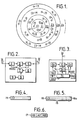
- a site as shown in Fig 1 has located therein a central receiver 12, transmitters 14 and repeaters 13.
- the site is divided into a number of zones, Z1, Z2, Z3. . . .Zn, and the repeaters in each zone are assigned zone address numbers related to their zone.
- the repeaters in zone 1 are nearest to the central receiver and those furthest away from the central reveiver have the highest zone number.
- Fig 2 One type of repeater is illustrated in Fig 2, and comprises a receiver aerial 1, transmitter aerial 5, receiver and demodulator 2, data message memory 3, transmitter 4, zone address memory 6, electronic control circuitry 7, mains power supply 8 and a rechargeable battery 9.
- the aim of the system is to relay messages which are originated by a transmitter 14, via a number of repeaters 13, to the central receiver 12. This is achieved as follows.
- Binary data messages are originated by transmitters 14 which may be at fixed positions on the site or may be mobile units carried by people or live stock or attached to objects which are moved around the site.
- Fig 4 shows a message from transmitter 14, which will consist of n bits of binary data 15, including error corrrection bits if required.
- the message will be received by one or more repeaters 13 and/or the central receiver 12.
- the message is received and demodulated by receiver and demodulator 2, then is stored in electronic memory 3 for a pre-set time controlled by electronic circuitry 7 and unique to that particular repeater.
- An additional m bits of data 16a are added to the message 15 to convey the repeater's zone number information.
- These m bits of zone number information may be stored in the zone address memory 6, or alternatively may be set during installation using switches, wire links etc, or similar means.
- the receiver and demodulator 2 sends a "received signal strength indication" or RSSI to the control circuitry 7 to allow the repeater to ensure that there is no traffic on the channel within its own range before retransmitting the message after the pre-set time delay. If the channel is clear, ie if the received signal strength indicator does not detect traffic on the channel, then the message is retransmitted by transmitter 4 through aerial 5.
- the message 16 which is transmitted (see Fig 5) is exactly the same as the original received message 15 with the zone number 16a added.
- This repeated message is then received by one or more repeaters 13 and/or the central receiver 12. Any repeater with a higher zone number or equal zone number to the zone number in the received message does not process the message any further. Repeaters with a lower zone number store the message in memory and overwrite the zone number with their own lower zone number before retransmitting (if the channel is clear) as described above. Thus, messages are passed by repeaters towards the central receiver 12, where the process stops.
- repeated messages 16 are delayed before being transmitted.
- the purpose of this delay is to prevent a situation where a message received by more than one repeater is re-transmitted exactly simultaneously causing the loss of the message due to traffic contention.
- the delay can be set using data in a further electronic memory, or alternatively using switches potentiometers or similar means, and each repeater on the site is set with a different delay during installation.
- the repeater units In the case of mains failure, the repeater units continue to operate using the rechargeable battery 9.
- the repeater automatically transmits a mains fail message 17 (see Fig 6) (after a pre-set delay) to alert the central receiver station of the mains failure.
- the pre-set delay is necessary to prevent traffic contention if mains fails generally on site to all the repeaters.
- repeaters operating on battery back-up may be programmed not to re-transmit a mains failure message, but simply to send an acknowledgement signal to the originating repeater.
- the mains fail message 17 will consist of a repeater identity 47, a mains fail message 49 and the zone address 48 as shown in Fig 6.
- the mains fail message 17 has a similar format to the repeated message 16, but the binary data 15 and 16a is replaced by the repeater identity code 47 and the mains fail message 49.
- the repeater identity 47 may be set in an electronic memory or using switches. It is also possible that the switches described above, which set the pre-set transmit delay, could define the repeater identity.
- the repeater of Figure 3 differs on that it uses a common transmit and receive aerial 11, and in that the control circuitry 7 controls a transmit/receive switch 10.
- the system of "zoned repeaters" and “site zones” as above described overcomes the problem of low transmitter operational range, which limits site size, and the coverage area can be increased indefinitely by adding further zones.
- the problems of traffic contention are reduced by the pre-set time delays in the repeaters which prevents those repeaters which received the same message from re-transmitting simultaneously, and also by the use of the RSSI output from the receiver 2 which is used to ensure that the channel is clear before transmission.
- the received signal strength indicator can be generated using the signal level at the receiver intermediate frequency, as is the case for RSSI on commercially available receiver integrated circuits, or alternatively the data protocol can be designed to enable simple detection of on-channel traffic. For example, if data messages are split into groups of bits separated by relatively long periods where unmodulated carrier is transmitted, then these long periods of "no data" and "no noise" out of the demodulator can be detected using appropriate electronic circuitry to indicate traffic on the channel.
- each repeater 29 has the repeater address uniquely set at manufacture and stored in repeater address memory 24 before despatch to the site. These pre-addressed repeaters are installed on site without regard to this address.
- Each repeater also includes a transmit/receive aerial 18, a transmit/receive switch 19, a receiver and demodulator 20, a message memory 21, a power supply 22, a battery backup 23, control circuitry 25, a destination address memory 26, a zone number memory 27 and a transmitter 28.
- the central receiver/transmitter 34 When all repeaters are positioned, the central receiver/transmitter 34 is operated to transmit a set up message 35 (see Fig 10) which consists of a "zone set up message" 36 (i.e. a series of data bits which are defined to alert any receiving equipment that a set up message follows), and zone number data 37 (the data in this case being 0, since the central receiver/transmitter is defined as the sole occupant of zone 0).
- This set up message is generated by an installation tool 55 (see Fig 13) and is transmitted by transmitter 49 in the central station via switch 48 and transmit/receive aerial 47.
- the installation tool may be a personal computer using software which generates standard messages and decodes replies, or alternatively can be dedicated equipment or part of the central station hardware.
- the central station also includes decoder circuitry 53, a rechargeable battery 54, mains supply 56, a receiver and demodulator 51 and control circuitry 52.
- Any repeater 29 within range of the central receiver/transmitter which receives this set up message 35 defines itself as an occupant of zone 1 and this zone number information is stored in memory 27 (see Fig 8).
- each of these zone 1 repeaters After a pre-set delay (different for each repeater) which may be random or may be derived electronically from the unique repeater address, each of these zone 1 repeaters transmits a repeater zone set up message which is similar to message 35 with the exception that the zone number 37 information is now set to zone 1.
- zone 2 Any repeaters within range and which receive this message define themselves as zone 2 (unless they have previously been defined as zone 0 or zone 1), and this set up procedure continues until all repeaters have defined themselves as part of a zone.
- the received signal strength indication from the receiver is used to define a lower acceptable limit for received signal strength during the set up procedure.
- control circuitry 25 of each repeater prevents the receiving repeater from defining itself as part of the higher zone.
- the transmitter power should be reduced to a fraction of the normal transmitter power in order to build in a safety margin.
- each repeater is instructed to transmit a repeater destination set up request 46 (see Fig 11) which consists of a standard request message 39 and its own address 40 which any receiving repeaters recognise as a repeater destination set up request. Any repeater which receives this message then transmits a repeater destination set up reply 43 (see Fig 12), consisting of a standard "reply message" 45, its address code 41, zone number 42 and the address of the requesting repeater 40.
- the reply messages 43 include the requesting repeater's address in order to direct the message to the correct repeater.
- the requesting repeater receives messages from any replying repeaters, and compiles a list of neighbouring repeaters which are in-range. This list is compiled in zone order, those with lowest zone number (ie nearest to the central receiver) first. Any replying repeaters which have the same zone number are listed in reply order, but this is not important to the operation of the system. If desired, the order of destination repeaters listed within the same zone may be periodically amended by the repeater control circuitry, based on a statistical monitoring of failed transmissions for each destination repeater. These destination addresses are stored in memory 26 of the repeater.
- This repeater destination set up procedure is initiated by the installer using the installation tool 55 to send a message from the central station transmitter which is received by all repeaters (possibly via other repeaters) and is recognised as an instruction to initiate the destination set up procedure. After a delay, each repeater retransmits the initial message without modification, then after a futher delay each repeater transmits its destination request message 46.
- each repeater After all repeaters have transmitted their repeater destination set up request messages 46 and stored all repeater destination set up replies 43, each repeater will hold in its memory 26 a list of other in-range repeaters' addresses and their corresponding zone numbers.
- the installer sends a "list addresses" message from the central station transmitter using the installation tool which instructs all repeaters (which may receive the instruction via other repeaters) to transmit a list of the destination addresses in memory 26.
- Each repeater receives this "list addresses" instruction, and after a delay retransmits it on to other repeaters, then after a further delay it transmits data containing its own address and a list of destination addresses.
- a full list of all repeater addresses and their destination addresses is compiled and displayed using the installation tool 55. All repeaters should have at least two repeaters in this list. If any do not, then the installer can install further repeaters. Thus, the installation procedure is considerably simplified since only the transmitter 14 to repeater 29 propagation needs to be considered in detail.
- the repeater to repeater path can be considered using a approximate "typical" range and sited on this basis and any holes in repeater to repeater coverage are automatically discovered and made apparent to the installer at either the zone set up stage or the destination set up stage.
- a message When a message is transmitted by a transmitter 14 it is received by one or more repeaters which then format a message 57 as shown in Fig 9.
- the destination address 31 is that which is top of the list of destination addresses ie, that which is nearest to the central station. This message is then retransmitted and is received by one or more neighbouring repeaters, but only the repeater with the specified address will process the data any further.
- the addressed repeater places the destination address code from the top of its own list in the message which is then retransmitted.
- This new message will be received by neighbouring repeaters including the previous repeater which monitors the channel until it receives this message which acts as confirmation that the message has been received correctly. This process is continued until the message is received by the central receiver where the repetition stops.
- path loss between repeaters is equal in both the transmit and the receive direction. It is therefore preferred to use a common Tx/Rx aerial on each repeater.
- a previous repeater fails to receive its message acknowledgement from the next repeater in the chain then it selects the second address on its list of destination addresses and repeats the message for a second time.
- a repeater fails to retransmit the message for any reason, for example if a receiver has become faulty or if a shield is temporarily placed between repeaters in the signal path then the message is intelligently re-directed via another repeater.
- any repeater Before any repeater transmits a message it monitors the channel for traffic (using the RSSI from its receiver for example) to ensure that the channel is clear of other transmissions before transmitting data itself, thus reducing the possibility of traffic contention. If a message has been contended with and has been corrupted then the receiving repeater detects this since the error check bits will be incorrect. The receiving repeater then transmits a "message corrupted" message to the original repeater, which would be monitoring for receipt of an acknowledgement signal in the form of a repetition of its own message. Receipt of "message corrupted" message rather than the acknowledgement signal initiates a re-transmission of the original message. If the mains supply fails to a repeater then the repeater transmits a message to the central station to indicate that it is operating on battery back-up.
- the system of intelligent repeaters and site zones provides a system which allows site size to be increased with a very low probability of traffic contention and a very high probability that messages are received by the central station accurately and quickly.
- the system is designed to make the commissioning of repeaters a simple task which can be performed by a single installer operating from the central station.
Landscapes
- Engineering & Computer Science (AREA)
- Computer Networks & Wireless Communication (AREA)
- Signal Processing (AREA)
- Radio Relay Systems (AREA)
- Mobile Radio Communication Systems (AREA)
- Small-Scale Networks (AREA)
Applications Claiming Priority (2)
| Application Number | Priority Date | Filing Date | Title |
|---|---|---|---|
| GB898910997A GB8910997D0 (en) | 1989-05-12 | 1989-05-12 | Radio transmission system |
| GB8910997 | 1989-05-12 |
Publications (3)
| Publication Number | Publication Date |
|---|---|
| EP0401974A2 true EP0401974A2 (de) | 1990-12-12 |
| EP0401974A3 EP0401974A3 (de) | 1991-10-23 |
| EP0401974B1 EP0401974B1 (de) | 1995-08-16 |
Family
ID=10656672
Family Applications (1)
| Application Number | Title | Priority Date | Filing Date |
|---|---|---|---|
| EP90304884A Expired - Lifetime EP0401974B1 (de) | 1989-05-12 | 1990-05-04 | Funkübertragungssystem mit einer Frequenz |
Country Status (5)
| Country | Link |
|---|---|
| US (1) | US5129096A (de) |
| EP (1) | EP0401974B1 (de) |
| CA (1) | CA2016486A1 (de) |
| DE (1) | DE69021642D1 (de) |
| GB (1) | GB8910997D0 (de) |
Cited By (9)
| Publication number | Priority date | Publication date | Assignee | Title |
|---|---|---|---|---|
| EP0526388A3 (en) * | 1991-08-01 | 1993-12-22 | City Communications Ltd | Radio communication system wherein transceivers retransmit messages in synchronism |
| US5455569A (en) * | 1992-03-25 | 1995-10-03 | Aes Corporation | Link layered communications network and method |
| EP0704991A1 (de) * | 1994-09-28 | 1996-04-03 | Philips Patentverwaltung GmbH | Synchronisation von zentralen Funkeinrichtungen |
| WO1998013953A1 (de) * | 1996-09-25 | 1998-04-02 | Mitsubishi International Gmbh | Mobilfunkendgerät/mobilfunkrelais |
| FR2786649A1 (fr) * | 1998-10-16 | 2000-06-02 | Daimler Chrysler Ag | Procede pour diffuser une information dans une partie incomplete d'un reseau de radiocommunication |
| GB2365698A (en) * | 2000-07-20 | 2002-02-20 | Liou Jenn Chorng | Mutually-assisted proximity informer system and method with wireless devices |
| EP2453641A4 (de) * | 2010-07-07 | 2012-06-06 | Panasonic Corp | Verstärker, automatisiertes drahtloses messgerätlesesystem damit und relaisverfahren dafür |
| EP2930861A1 (de) * | 2014-04-09 | 2015-10-14 | OTA Systems Oy | Funk-repeater |
| EP3035762A4 (de) * | 2013-08-13 | 2016-10-26 | Hytera Comm Corp Ltd | Anrufkollisionsverarbeitungsverfahren, endgerät und transferplattform |
Families Citing this family (121)
| Publication number | Priority date | Publication date | Assignee | Title |
|---|---|---|---|---|
| US5239671A (en) * | 1990-11-13 | 1993-08-24 | Pagemart, Inc. | Simulcast satellite paging system with provision for signal interruption |
| US5265150A (en) * | 1991-01-30 | 1993-11-23 | At&T Bell Laboratories | Automatically configuring wireless PBX system |
| JPH0530000A (ja) * | 1991-07-18 | 1993-02-05 | Fujitsu Ltd | 移動体通信方式 |
| US5475867A (en) * | 1992-02-06 | 1995-12-12 | Itron, Inc. | Distributed supervisory control and data acquisition system |
| US5974236A (en) * | 1992-03-25 | 1999-10-26 | Aes Corporation | Dynamically reconfigurable communications network and method |
| US5377255A (en) * | 1992-07-14 | 1994-12-27 | Pcs Microcell International Inc. | RF repeaters for time division duplex cordless telephone systems |
| US5459759A (en) * | 1993-02-17 | 1995-10-17 | Interdigital Technology Corporation | Frequency hopping code division multiple access system and method |
| US7142582B2 (en) * | 1993-02-17 | 2006-11-28 | Interdigital Technology Corporation | Receiving and selectively transmitting frequency hopped data signals using a plurality of antennas |
| US5446924A (en) * | 1993-05-03 | 1995-08-29 | Motorola, Inc. | Method for assuring data integrity during a repeater transition |
| US5345600A (en) * | 1993-08-31 | 1994-09-06 | Motorola, Inc. | Method and apparatus for selectively-enabled diversity signaling in a radio communications system |
| US5479400A (en) * | 1994-06-06 | 1995-12-26 | Metricom, Inc. | Transceiver sharing between access and backhaul in a wireless digital communication system |
| US20070064771A1 (en) * | 1994-08-29 | 2007-03-22 | Interdigital Technology Corporation | Receiving and selectively transmitting frequency hopped data signals using a plurality of antennas |
| US6097707A (en) * | 1995-05-19 | 2000-08-01 | Hodzic; Migdat I. | Adaptive digital wireless communications network apparatus and process |
| US5652751A (en) * | 1996-03-26 | 1997-07-29 | Hazeltine Corporation | Architecture for mobile radio networks with dynamically changing topology using virtual subnets |
| US6078785A (en) * | 1996-10-15 | 2000-06-20 | Bush; E. William | Demand reporting of electricity consumption by radio in relays to a base station, and demand relays wattmeters so reporting over a wide area |
| US5901355A (en) * | 1996-11-01 | 1999-05-04 | Airnet Communications Corp. | Method using different frequencies and antenna types for remotes located in an inner or outer region of a cell |
| US6396839B1 (en) | 1997-02-12 | 2002-05-28 | Abb Automation Inc. | Remote access to electronic meters using a TCP/IP protocol suite |
| JP3756344B2 (ja) * | 1999-05-11 | 2006-03-15 | 京セラ株式会社 | マルチモード携帯電話装置 |
| CA2391405C (en) * | 2000-04-10 | 2006-01-10 | Zensys A/S | Rf home automation system comprising replicable controllers |
| US6647053B1 (en) | 2000-08-31 | 2003-11-11 | Ricochet Networks, Inc. | Method and system for channel masking in a communication network |
| US20100330930A1 (en) * | 2000-12-22 | 2010-12-30 | Twitchell Robert W | Lprf device wake up using wireless tag |
| US7391321B2 (en) * | 2005-01-10 | 2008-06-24 | Terahop Networks, Inc. | Keyhole communication device for tracking and monitoring shipping container and contents thereof |
| US7133704B2 (en) * | 2000-12-22 | 2006-11-07 | Terahop Networks, Inc. | Manufacture of LPRF device wake up using wireless tag |
| US7522568B2 (en) * | 2000-12-22 | 2009-04-21 | Terahop Networks, Inc. | Propagating ad hoc wireless networks based on common designation and routine |
| US7200132B2 (en) * | 2000-12-22 | 2007-04-03 | Terahop Networks, Inc. | Forming ad hoc RSI networks among transceivers sharing common designation |
| US8315563B2 (en) * | 2000-12-22 | 2012-11-20 | Google Inc. | Wireless reader tags (WRTs) with sensor components in asset monitoring and tracking systems |
| US7209468B2 (en) * | 2000-12-22 | 2007-04-24 | Terahop Networks, Inc. | Forming communication cluster of wireless AD HOC network based on common designation |
| US7539520B2 (en) * | 2005-06-17 | 2009-05-26 | Terahop Networks, Inc. | Remote sensor interface (RSI) having power conservative transceiver for transmitting and receiving wakeup signals |
| US7583769B2 (en) * | 2005-06-16 | 2009-09-01 | Terahop Netowrks, Inc. | Operating GPS receivers in GPS-adverse environment |
| US7733818B2 (en) * | 2000-12-22 | 2010-06-08 | Terahop Networks, Inc. | Intelligent node communication using network formation messages in a mobile Ad hoc network |
| US7830273B2 (en) * | 2005-08-18 | 2010-11-09 | Terahop Networks, Inc. | Sensor networks for pipeline monitoring |
| US20080303897A1 (en) * | 2000-12-22 | 2008-12-11 | Terahop Networks, Inc. | Visually capturing and monitoring contents and events of cargo container |
| US7554442B2 (en) * | 2005-06-17 | 2009-06-30 | Terahop Networks, Inc. | Event-driven mobile hazmat monitoring |
| US7574168B2 (en) * | 2005-06-16 | 2009-08-11 | Terahop Networks, Inc. | Selective GPS denial system |
| US6745027B2 (en) | 2000-12-22 | 2004-06-01 | Seekernet Incorporated | Class switched networks for tracking articles |
| US7526381B2 (en) * | 2005-06-03 | 2009-04-28 | Terahop Networks, Inc. | Network aided terrestrial triangulation using stars (NATTS) |
| US7542849B2 (en) * | 2005-06-03 | 2009-06-02 | Terahop Networks, Inc. | Network aided terrestrial triangulation using stars (NATTS) |
| US7221668B2 (en) * | 2000-12-22 | 2007-05-22 | Terahop Networks, Inc. | Communications within population of wireless transceivers based on common designation |
| US6934540B2 (en) * | 2000-12-22 | 2005-08-23 | Seekernet, Inc. | Network formation in asset-tracking system based on asset class |
| US7783246B2 (en) * | 2005-06-16 | 2010-08-24 | Terahop Networks, Inc. | Tactical GPS denial and denial detection system |
| US7574300B2 (en) * | 2005-06-16 | 2009-08-11 | Terahop Networks, Inc. | GPS denial device detection and location system |
| US7705747B2 (en) * | 2005-08-18 | 2010-04-27 | Terahop Networks, Inc. | Sensor networks for monitoring pipelines and power lines |
| US7430437B2 (en) * | 2000-12-22 | 2008-09-30 | Terahop Networks, Inc. | Transmitting sensor-acquired data using step-power filtering |
| US7209771B2 (en) * | 2000-12-22 | 2007-04-24 | Terahop Networks, Inc. | Battery powered wireless transceiver having LPRF component and second wake up receiver |
| US7155264B2 (en) * | 2000-12-22 | 2006-12-26 | Terahop Networks, Inc. | Systems and methods having LPRF device wake up using wireless tag |
| US7563991B2 (en) * | 2005-06-08 | 2009-07-21 | Terahop Networks, Inc. | All weather housing assembly for electronic components |
| US7551562B2 (en) * | 2000-12-29 | 2009-06-23 | Tropos Networks | Determining bidirectional path quality within a wireless mesh network |
| US6879806B2 (en) | 2001-06-01 | 2005-04-12 | Zensys A/S | System and a method for building routing tables and for routing signals in an automation system |
| US6999441B2 (en) * | 2001-06-27 | 2006-02-14 | Ricochet Networks, Inc. | Method and apparatus for contention management in a radio-based packet network |
| US7068630B1 (en) | 2001-07-31 | 2006-06-27 | Ricochet Networks, Inc. | Method for measuring load between MCDN devices for use in determining path with optimal throughput |
| AU2003238968A1 (en) * | 2002-06-11 | 2003-12-22 | Meshnetworks, Inc. | System and method for multicast media access in ad-hoc communication networks |
| US7119713B2 (en) | 2002-06-27 | 2006-10-10 | Elster Electricity, Llc | Dynamic self-configuring metering network |
| US20040113810A1 (en) | 2002-06-28 | 2004-06-17 | Mason Robert T. | Data collector for an automated meter reading system |
| US7792089B2 (en) * | 2002-07-31 | 2010-09-07 | Cattron-Theimeg, Inc. | System and method for wireless remote control of locomotives |
| US9077991B2 (en) | 2002-12-10 | 2015-07-07 | Sony Computer Entertainment America Llc | System and method for utilizing forward error correction with video compression |
| US7493078B2 (en) * | 2002-12-10 | 2009-02-17 | Onlive, Inc. | Antenna assembly for satellite and wireless services |
| US9138644B2 (en) * | 2002-12-10 | 2015-09-22 | Sony Computer Entertainment America Llc | System and method for accelerated machine switching |
| US7849491B2 (en) | 2002-12-10 | 2010-12-07 | Onlive, Inc. | Apparatus and method for wireless video gaming |
| US20090118019A1 (en) | 2002-12-10 | 2009-05-07 | Onlive, Inc. | System for streaming databases serving real-time applications used through streaming interactive video |
| US7558525B2 (en) * | 2002-12-10 | 2009-07-07 | Onlive, Inc. | Mass storage repository for a wireless network |
| US8526490B2 (en) | 2002-12-10 | 2013-09-03 | Ol2, Inc. | System and method for video compression using feedback including data related to the successful receipt of video content |
| US9446305B2 (en) | 2002-12-10 | 2016-09-20 | Sony Interactive Entertainment America Llc | System and method for improving the graphics performance of hosted applications |
| US8711923B2 (en) | 2002-12-10 | 2014-04-29 | Ol2, Inc. | System and method for selecting a video encoding format based on feedback data |
| US8549574B2 (en) | 2002-12-10 | 2013-10-01 | Ol2, Inc. | Method of combining linear content and interactive content compressed together as streaming interactive video |
| US7684752B2 (en) * | 2002-12-10 | 2010-03-23 | Onlive, Inc. | Wireless network providing distributed video / data services |
| US8366552B2 (en) | 2002-12-10 | 2013-02-05 | Ol2, Inc. | System and method for multi-stream video compression |
| US9192859B2 (en) | 2002-12-10 | 2015-11-24 | Sony Computer Entertainment America Llc | System and method for compressing video based on latency measurements and other feedback |
| US8964830B2 (en) * | 2002-12-10 | 2015-02-24 | Ol2, Inc. | System and method for multi-stream video compression using multiple encoding formats |
| US9314691B2 (en) | 2002-12-10 | 2016-04-19 | Sony Computer Entertainment America Llc | System and method for compressing video frames or portions thereof based on feedback information from a client device |
| US9108107B2 (en) | 2002-12-10 | 2015-08-18 | Sony Computer Entertainment America Llc | Hosting and broadcasting virtual events using streaming interactive video |
| US9061207B2 (en) | 2002-12-10 | 2015-06-23 | Sony Computer Entertainment America Llc | Temporary decoder apparatus and method |
| US20040110468A1 (en) * | 2002-12-10 | 2004-06-10 | Perlman Stephen G. | Wireless network with presentation and media layers for broadcast satellite and cable services |
| US10201760B2 (en) | 2002-12-10 | 2019-02-12 | Sony Interactive Entertainment America Llc | System and method for compressing video based on detected intraframe motion |
| US7590084B2 (en) | 2003-02-14 | 2009-09-15 | Onlive, Inc. | Self-configuring, adaptive, three-dimensional, wireless network |
| US7215660B2 (en) | 2003-02-14 | 2007-05-08 | Rearden Llc | Single transceiver architecture for a wireless network |
| US7593361B2 (en) * | 2003-02-14 | 2009-09-22 | Onlive, Inc. | Method of operation for a three-dimensional, wireless network |
| US7593688B2 (en) * | 2003-12-12 | 2009-09-22 | Subscriber Solutions, Inc. | Delay based space and time coordinated repeater system |
| US7522876B1 (en) * | 2004-04-21 | 2009-04-21 | Phc Llc | Distributed access gateway and wireless router pods and public safety communications infrastructure incorporating the same |
| US7187906B2 (en) | 2004-04-26 | 2007-03-06 | Elster Electricity, Llc | Method and system for configurable qualification and registration in a fixed network automated meter reading system |
| US7239250B2 (en) | 2004-04-26 | 2007-07-03 | Elster Electricity, Llc | System and method for improved transmission of meter data |
| US7262709B2 (en) | 2004-04-26 | 2007-08-28 | Elster Electricity, Llc | System and method for efficient configuration in a fixed network automated meter reading system |
| US7142107B2 (en) | 2004-05-27 | 2006-11-28 | Lawrence Kates | Wireless sensor unit |
| US7142106B2 (en) | 2004-06-15 | 2006-11-28 | Elster Electricity, Llc | System and method of visualizing network layout and performance characteristics in a wireless network |
| US7742430B2 (en) | 2004-09-24 | 2010-06-22 | Elster Electricity, Llc | System for automated management of spontaneous node migration in a distributed fixed wireless network |
| US7702594B2 (en) | 2004-09-24 | 2010-04-20 | Elster Electricity, Llc | System and method for automated configuration of meters |
| US7176807B2 (en) | 2004-09-24 | 2007-02-13 | Elster Electricity, Llc | System for automatically enforcing a demand reset in a fixed network of electricity meters |
| US7170425B2 (en) | 2004-09-24 | 2007-01-30 | Elster Electricity, Llc | System and method for creating multiple operating territories within a meter reading system |
| US7327998B2 (en) | 2004-12-22 | 2008-02-05 | Elster Electricity, Llc | System and method of providing a geographic view of nodes in a wireless network |
| WO2006074465A2 (en) * | 2005-01-10 | 2006-07-13 | Seekernet Incorporated | Keyhole communication device for tracking and monitoring shipping container and contents thereof |
| US7308370B2 (en) | 2005-03-22 | 2007-12-11 | Elster Electricity Llc | Using a fixed network wireless data collection system to improve utility responsiveness to power outages |
| WO2007100343A1 (en) * | 2005-06-03 | 2007-09-07 | Terahop Networks Inc. | Remote sensor interface (rsi) stepped wake-up sequence |
| EP1905200A1 (de) | 2005-07-01 | 2008-04-02 | Terahop Networks, Inc. | Nichtdeterministisches und deterministisches netzwerk-routing |
| US7828342B2 (en) * | 2005-07-29 | 2010-11-09 | Terahop Networks, Inc. | Reusable locking body, of bolt-type seal lock, having open-ended passageway and U-shaped bolt |
| US7495578B2 (en) | 2005-09-02 | 2009-02-24 | Elster Electricity, Llc | Multipurpose interface for an automated meter reading device |
| US7308369B2 (en) | 2005-09-28 | 2007-12-11 | Elster Electricity Llc | Ensuring automatic season change demand resets in a mesh type network of telemetry devices |
| WO2007067831A1 (en) * | 2005-10-31 | 2007-06-14 | Terahop Networks, Inc. | Determining relative elevation using gps and ranging |
| US7694005B2 (en) | 2005-11-04 | 2010-04-06 | Intermatic Incorporated | Remote device management in a home automation data transfer system |
| US7640351B2 (en) | 2005-11-04 | 2009-12-29 | Intermatic Incorporated | Application updating in a home automation data transfer system |
| US7698448B2 (en) | 2005-11-04 | 2010-04-13 | Intermatic Incorporated | Proxy commands and devices for a home automation data transfer system |
| US7870232B2 (en) | 2005-11-04 | 2011-01-11 | Intermatic Incorporated | Messaging in a home automation data transfer system |
| WO2008036425A1 (en) * | 2006-01-01 | 2008-03-27 | Terahop Networks, Inc. | Determining presence of radio frequency communication device |
| US20090129306A1 (en) * | 2007-02-21 | 2009-05-21 | Terahop Networks, Inc. | Wake-up broadcast including network information in common designation ad hoc wireless networking |
| US7427927B2 (en) | 2006-02-16 | 2008-09-23 | Elster Electricity, Llc | In-home display communicates with a fixed network meter reading system |
| US7545285B2 (en) | 2006-02-16 | 2009-06-09 | Elster Electricity, Llc | Load control unit in communication with a fixed network meter reading system |
| US7990255B2 (en) * | 2006-11-02 | 2011-08-02 | Audiovox Corporation | Range extending positive repeater |
| US8073384B2 (en) | 2006-12-14 | 2011-12-06 | Elster Electricity, Llc | Optimization of redundancy and throughput in an automated meter data collection system using a wireless network |
| US7729278B2 (en) | 2007-02-14 | 2010-06-01 | Tropos Networks, Inc. | Wireless routing based on data packet classifications |
| US8223680B2 (en) * | 2007-02-21 | 2012-07-17 | Google Inc. | Mesh network control using common designation wake-up |
| US8320302B2 (en) | 2007-04-20 | 2012-11-27 | Elster Electricity, Llc | Over the air microcontroller flash memory updates |
| US9168457B2 (en) | 2010-09-14 | 2015-10-27 | Sony Computer Entertainment America Llc | System and method for retaining system state |
| WO2009082761A1 (en) | 2007-12-26 | 2009-07-02 | Elster Electricity, Llc. | Optimized data collection in a wireless fixed network metering system |
| JP5281312B2 (ja) * | 2008-04-25 | 2013-09-04 | キヤノン株式会社 | 通信装置及びその制御方法、コンピュータプログラム |
| US8462662B2 (en) * | 2008-05-16 | 2013-06-11 | Google Inc. | Updating node presence based on communication pathway |
| WO2009151877A2 (en) | 2008-05-16 | 2009-12-17 | Terahop Networks, Inc. | Systems and apparatus for securing a container |
| US8525692B2 (en) | 2008-06-13 | 2013-09-03 | Elster Solutions, Llc | Techniques for limiting demand from an electricity meter with an installed relay |
| US8391435B2 (en) | 2008-12-25 | 2013-03-05 | Google Inc. | Receiver state estimation in a duty cycled radio |
| US8300551B2 (en) * | 2009-01-28 | 2012-10-30 | Google Inc. | Ascertaining presence in wireless networks |
| US8705523B2 (en) * | 2009-02-05 | 2014-04-22 | Google Inc. | Conjoined class-based networking |
| US8203463B2 (en) | 2009-02-13 | 2012-06-19 | Elster Electricity Llc | Wakeup and interrogation of meter-reading devices using licensed narrowband and unlicensed wideband radio communication |
| US8346160B2 (en) | 2010-05-12 | 2013-01-01 | Andrew Llc | System and method for detecting and measuring uplink traffic in signal repeating systems |
| US9112790B2 (en) | 2013-06-25 | 2015-08-18 | Google Inc. | Fabric network |
Family Cites Families (8)
| Publication number | Priority date | Publication date | Assignee | Title |
|---|---|---|---|---|
| US4255814A (en) * | 1977-07-15 | 1981-03-10 | Motorola, Inc. | Simulcast transmission system |
| DE2856019A1 (de) * | 1978-12-23 | 1980-07-10 | Bosch Gmbh Robert | Sprechfunknetz mit einer hauptstation, mindestens zwei auf demselben funkkanal arbeitenden relaisstationen und mit mehreren unterstationen |
| DE3206133A1 (de) * | 1982-02-20 | 1983-09-01 | Robert Bosch Gmbh, 7000 Stuttgart | Verfahren zur funkuebertragung digitaler informationen mittels einer uebertragungsfrequenz |
| DE3210298A1 (de) * | 1982-03-20 | 1983-09-29 | Robert Bosch Gmbh, 7000 Stuttgart | Diversity-funknetz |
| US4475246A (en) * | 1982-12-21 | 1984-10-02 | Motorola, Inc. | Simulcast same frequency repeater system |
| US4479245A (en) * | 1982-12-21 | 1984-10-23 | Motorola, Inc. | Same frequency repeater for a multiple repeater system |
| CA1235751A (en) * | 1985-01-09 | 1988-04-26 | Junji Namiki | One frequency repeater for a digital microwave radio system with cancellation of transmitter-to-receiver interference |
| CA1246681A (en) * | 1985-01-30 | 1988-12-13 | Northern Telecom Limited | Terminal address assignment in a broadcast transmission system |
-
1989
- 1989-05-12 GB GB898910997A patent/GB8910997D0/en active Pending
-
1990
- 1990-05-04 EP EP90304884A patent/EP0401974B1/de not_active Expired - Lifetime
- 1990-05-04 DE DE69021642T patent/DE69021642D1/de not_active Expired - Lifetime
- 1990-05-04 US US07/518,457 patent/US5129096A/en not_active Expired - Fee Related
- 1990-05-10 CA CA002016486A patent/CA2016486A1/en not_active Abandoned
Cited By (12)
| Publication number | Priority date | Publication date | Assignee | Title |
|---|---|---|---|---|
| EP0526388A3 (en) * | 1991-08-01 | 1993-12-22 | City Communications Ltd | Radio communication system wherein transceivers retransmit messages in synchronism |
| US5369784A (en) * | 1991-08-01 | 1994-11-29 | City Communications Limited | Radio communications system using multiple simultaneously transmitting transceivers |
| US5455569A (en) * | 1992-03-25 | 1995-10-03 | Aes Corporation | Link layered communications network and method |
| EP0704991A1 (de) * | 1994-09-28 | 1996-04-03 | Philips Patentverwaltung GmbH | Synchronisation von zentralen Funkeinrichtungen |
| WO1998013953A1 (de) * | 1996-09-25 | 1998-04-02 | Mitsubishi International Gmbh | Mobilfunkendgerät/mobilfunkrelais |
| FR2786649A1 (fr) * | 1998-10-16 | 2000-06-02 | Daimler Chrysler Ag | Procede pour diffuser une information dans une partie incomplete d'un reseau de radiocommunication |
| GB2365698A (en) * | 2000-07-20 | 2002-02-20 | Liou Jenn Chorng | Mutually-assisted proximity informer system and method with wireless devices |
| US6950413B1 (en) * | 2000-07-20 | 2005-09-27 | Jenn-Chorng Liou | Mutually-assisted proximity informer system and method with wireless devices |
| EP2453641A4 (de) * | 2010-07-07 | 2012-06-06 | Panasonic Corp | Verstärker, automatisiertes drahtloses messgerätlesesystem damit und relaisverfahren dafür |
| EP3035762A4 (de) * | 2013-08-13 | 2016-10-26 | Hytera Comm Corp Ltd | Anrufkollisionsverarbeitungsverfahren, endgerät und transferplattform |
| US10091823B2 (en) | 2013-08-13 | 2018-10-02 | Hytera Communications Corporation Limited | Call collision processing method, terminal and transfer platform |
| EP2930861A1 (de) * | 2014-04-09 | 2015-10-14 | OTA Systems Oy | Funk-repeater |
Also Published As
| Publication number | Publication date |
|---|---|
| DE69021642D1 (de) | 1995-09-21 |
| EP0401974A3 (de) | 1991-10-23 |
| CA2016486A1 (en) | 1990-11-12 |
| GB8910997D0 (en) | 1989-06-28 |
| EP0401974B1 (de) | 1995-08-16 |
| US5129096A (en) | 1992-07-07 |
Similar Documents
| Publication | Publication Date | Title |
|---|---|---|
| US5129096A (en) | System which routes radio transmissions to selected repeaters for retransmission | |
| US7672683B2 (en) | Non-interfering multipath communication system | |
| JP4396584B2 (ja) | 火災報知システム | |
| EP0781477B1 (de) | Gleitfrequenzkommunikationssystem, und sende-/ empfangsvorrichtung für das system | |
| EP0788689B1 (de) | Gebäudeleitsystem mit paketsprungübertragung | |
| US4882765A (en) | Data transmission system | |
| EP0940022B1 (de) | Leitweglenkung von nachrichten in drahtlosen netzen | |
| US4638298A (en) | Communication system having message repeating terminals | |
| EP2640111A1 (de) | Verfahren und Vorrichtung zur Steuerung eines drahtlosen Heimsystems | |
| US20040239497A1 (en) | Method and apparatus for two-way communications amongst a plurality of communications devices | |
| GB2131990A (en) | Remote system systems | |
| EP0330178B1 (de) | Satellitennachrichtübertragungssystem mit Vielfachzugriff und Ersatzzentralstation | |
| GB2056820A (en) | Method of radio data transmission | |
| US4222052A (en) | Data transmission system | |
| US7274907B1 (en) | Wireless instrumentation system and power management scheme therefore | |
| EP1201055B1 (de) | Verfahren und gerät für drahtlose kommunikation | |
| WO1996022636A1 (en) | Radio communications systems with repeaters using identification codes | |
| US7554932B1 (en) | Message control protocol in a communications network having repeaters | |
| US8320294B2 (en) | Method for communicating in a network comprising wire and wireless nodes | |
| JP2008004035A (ja) | 火災報知システム | |
| WO1994026039A1 (en) | Method for assuring data integrity during a repeater transition | |
| US7379730B2 (en) | Vehicle security system receiving acknowledgment of transmitted vehicle security message and related methods | |
| JP2810569B2 (ja) | ページング方式 | |
| JPS6013537B2 (ja) | 通信方式 | |
| ES2214456T3 (es) | Procedimiento para la radiotransmision en un sistema de alarma. |
Legal Events
| Date | Code | Title | Description |
|---|---|---|---|
| PUAI | Public reference made under article 153(3) epc to a published international application that has entered the european phase |
Free format text: ORIGINAL CODE: 0009012 |
|
| AK | Designated contracting states |
Kind code of ref document: A2 Designated state(s): DE DK FR GB NL SE |
|
| PUAL | Search report despatched |
Free format text: ORIGINAL CODE: 0009013 |
|
| AK | Designated contracting states |
Kind code of ref document: A3 Designated state(s): DE DK FR GB NL SE |
|
| 17P | Request for examination filed |
Effective date: 19920327 |
|
| 17Q | First examination report despatched |
Effective date: 19940207 |
|
| GRAA | (expected) grant |
Free format text: ORIGINAL CODE: 0009210 |
|
| AK | Designated contracting states |
Kind code of ref document: B1 Designated state(s): DE DK FR GB NL SE |
|
| PG25 | Lapsed in a contracting state [announced via postgrant information from national office to epo] |
Ref country code: FR Free format text: THE PATENT HAS BEEN ANNULLED BY A DECISION OF A NATIONAL AUTHORITY Effective date: 19950816 Ref country code: NL Free format text: LAPSE BECAUSE OF FAILURE TO SUBMIT A TRANSLATION OF THE DESCRIPTION OR TO PAY THE FEE WITHIN THE PRESCRIBED TIME-LIMIT Effective date: 19950816 Ref country code: DK Effective date: 19950816 |
|
| REF | Corresponds to: |
Ref document number: 69021642 Country of ref document: DE Date of ref document: 19950921 |
|
| PG25 | Lapsed in a contracting state [announced via postgrant information from national office to epo] |
Ref country code: SE Effective date: 19951116 |
|
| PG25 | Lapsed in a contracting state [announced via postgrant information from national office to epo] |
Ref country code: DE Effective date: 19951117 |
|
| EN | Fr: translation not filed | ||
| NLV1 | Nl: lapsed or annulled due to failure to fulfill the requirements of art. 29p and 29m of the patents act | ||
| PLBE | No opposition filed within time limit |
Free format text: ORIGINAL CODE: 0009261 |
|
| STAA | Information on the status of an ep patent application or granted ep patent |
Free format text: STATUS: NO OPPOSITION FILED WITHIN TIME LIMIT |
|
| 26N | No opposition filed | ||
| REG | Reference to a national code |
Ref country code: GB Ref legal event code: 732E |
|
| REG | Reference to a national code |
Ref country code: GB Ref legal event code: IF02 |
|
| REG | Reference to a national code |
Ref country code: GB Ref legal event code: 732E |
|
| PGFP | Annual fee paid to national office [announced via postgrant information from national office to epo] |
Ref country code: GB Payment date: 20090507 Year of fee payment: 20 |
|
| REG | Reference to a national code |
Ref country code: GB Ref legal event code: PE20 Expiry date: 20100503 |
|
| PG25 | Lapsed in a contracting state [announced via postgrant information from national office to epo] |
Ref country code: GB Free format text: LAPSE BECAUSE OF EXPIRATION OF PROTECTION Effective date: 20100503 |