EP0401988A2 - Dispositif pour retenir et/ou verser pour cuves pour bains de métaux coulées - Google Patents
Dispositif pour retenir et/ou verser pour cuves pour bains de métaux coulées Download PDFInfo
- Publication number
- EP0401988A2 EP0401988A2 EP90305293A EP90305293A EP0401988A2 EP 0401988 A2 EP0401988 A2 EP 0401988A2 EP 90305293 A EP90305293 A EP 90305293A EP 90305293 A EP90305293 A EP 90305293A EP 0401988 A2 EP0401988 A2 EP 0401988A2
- Authority
- EP
- European Patent Office
- Prior art keywords
- molten metal
- outlet
- means according
- starting tube
- protective ring
- Prior art date
- Legal status (The legal status is an assumption and is not a legal conclusion. Google has not performed a legal analysis and makes no representation as to the accuracy of the status listed.)
- Granted
Links
Images

Classifications
-
- B—PERFORMING OPERATIONS; TRANSPORTING
- B22—CASTING; POWDER METALLURGY
- B22D—CASTING OF METALS; CASTING OF OTHER SUBSTANCES BY THE SAME PROCESSES OR DEVICES
- B22D43/00—Mechanical cleaning, e.g. skimming of molten metals
- B22D43/001—Retaining slag during pouring molten metal
- B22D43/002—Retaining slag during pouring molten metal by using floating means
Definitions
- the invention relates to a means for retaining contaminations contained in a melting bath, i.e. containing molten metal, in a vessel, e.g. a tank, a ladle, a distribution means, a tundish and the like.
- a melting bath i.e. containing molten metal
- a vessel e.g. a tank, a ladle, a distribution means, a tundish and the like.
- the invention particularly relates to a pouring means for tundishes for receiving molten metal (steel) and for passing it on into ingot moulds or into the mould of a continuous casting plant but is not limited thereto.
- the steel is passed from a ladle into a tundish, which has outlets in the bottom corresponding to the positions of the moulds.
- the tundish is either provided with slide gate nozzles from below or with plugs from above, or, in the case of free-runs, with outlet nozzles only.
- the outlet areas are heated before use by means of burners, from below or from above, in order to avoid chilling during the start-up of casting.
- the first portion of the steel reaching the tundish and distributing there up to the outlets, is coined by low temperatures and contaminations, which result e.g. from refractory particles from the lining, from sand and from the oxidation of the steel during the start-up of the casting.
- dams built in for avoiding these problems, which dams were intended to effect a rise of the contaminations due to the damming up of the initial steel and which were also intended to raise the initial casting temperatures due to the high steel volume by mixing the subsequent hot steel with the initially cold steel.
- This could not prevent the contaminations floating on the surface from reaching the outlets during the starting phase, thus leading, as already described, to a devaluation of the initial steel strand or to difficulties in the starting procedure of casting.
- filters proposed for use in the outlet were not able to solve these problems due to blockings or difficulties in chilling.
- starting tubes were used with sliding gate nozzles, independently from the damming and filtering above the outlets, which starting tubes with their cylindrical shape and with a diameter corresponding to the outlet sprue, caused a temporary bulkheading off of the outlet which, though raising the starting temperature, were incapable of preventing the contaminations floating on the surface, when reaching the top of the starting tube or the overflow openings provided in the starting tube, to be the first to enter the outlet.
- the present invention is based on the problem of providing means of the initially mentioned kind in a manner as to ensure that the cast strand does not contain contaminations.
- the gist of the invention is an annular buoyancy body in the form of a protective ring which is either conducted on the starting tube or the plug or, in the case of free-runs, on a suitable means in a manner that it prevents slag from reaching the outlet.
- the protective ring serves as an inhibit member and projects with its upper part from the surface of the molten bath level to such an extent that no slag particles or the like can pass, across its upper rim, to the inner space of the protective ring.
- the projection above the bath level can be achieved by selecting the shape of the protective ring and its specific weight in correspondence to the particles floating on the surface of the melting bath or of the melting bath itself, independently from the actual level of the bath.
- the protective ring can also be fixed at a specific position with respect to the starting tube or its overflow openings. This can counteract the unwanted Vortex-effect, namely, the level in the tundish dropping on the occasion of an exchange of ladles.
- the starting tube can also be provided with openings in its lower region too.
- said openings are at first closed by pieces of sheet material so that at first they do not have any function when casting starts up. Under the action of the high temperatures of the melting bath these sheets are eventually melted so that now steel can flow through said openings into the outlet. In the normal melting procedure this actually is not necessary, since the overflow openings in the upper part of the starting tube meet this function. At the end of the sequence, however, these lower openings take over the function that the steel can flow out of the tundish so that only a small residue will result (so-called button).
- a tundish 13 is provided with a lining 13A which can be replaced upon wear. Underneath said lining 13 there is a permanent lining 14 and an insulating lining 15. 16 refers to the casing of the tundish itself.
- the tundish has an outlet or pouring opening 4 in its base and the entrance to the outlet is surrounded inside the tundish by a starting tube 1.
- Starting tube 1 has openings 3 towards its upper end.
- a protective ring 2 surrounds starting tube 1 and rests on the base of the tundish when the latter is empty.
- the surface of the molten steel is covered with a slag layer 11 and a covering insulating layer 10 both of which represent a source of contaminating particles for the steel to be poured through outlet 4.
- starting tube of Figure 1 is open-topped whereas in the embodiment shown in Figure 2, starting tube 1 has a lid 23 of greater diameter than tube 1 so that it projects beyond the tube at 21.
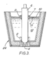
- FIG 3 a tundish 24 having an outlet 4 in its base that is closed by a plug 6.
- a protective ring 2 surrounds plug 6 and sits on the floor of the tundish when it is empty or just starting to fill with molten steel 12.
- the operation of protective ring 2 is very similar to that used with the starting tube 1 of Figures 1 and 2. Indeed, for convenience, since the conditions relating to use of the present invention for the individual pouring means, namely with a sliding gate nozzle 17 or with a plug 6 or as free-run are rather similar, the invention is subsequently described and explained principally in connection with Figures 1 and 2.
- Starting tube 1 as shown in Figure 1 has an inner diameter corresponding to the diameter of the outlet and is attached to the tundish base surrounding outlet 4 and fastened and sealed so that during the initial phase steel cannot reach outlet 4 directly and that tube 1 cannot float up.
- Said tube 1 is open at the top and has slots 3 towards its upper end at a predetermined distance from the tundish base which slots are dimensioned such that the amount of steel that can flow through is larger than that corresponding to the predetermined diameter of the outlet.
- a protective ring 2 the goemetrical shape and buoyancy of which is such that it floats up due to the buoyancy caused by the steel 12 and assumes a floating position partially submerged in the steel 12 and partly protruding above slag 11 and insulating layer 10.
- tube 1 inhibits, as long as it remains in place, and even when ladles are exchanged, characterised by a drop in the steel level, the so-called Vortex-effect, i.e. the drawing-in of slag into the outlet.
- Vortex-effect i.e. the drawing-in of slag into the outlet.
- tube 1 is designed in a manner that at the end of the sequence it will leave its position and float up or that it is mechanically forced to do so.
- tube 1 may be designed in a manner that floating ring 2 is prevented from floating up further at the upper part of tube 1 during the casting procedure. This embodiment is shown in Figure 2.
- the starting tube 1 is provided with overflow openings 3, which have a specific height and which are distributed over the circumference of starting tube 1.
- Overflow openings 3 have a total surface which is adjusted to the inlet opening of outlet 4.
- tube 1 is provided with a cover 23, which may be integral or a separate lid.
- Numeral 21 designates a projection of cover 23 which prevents the floating protective ring from disengaging from starting tube 1 in the upward direction - as shown in dotted form at the right hand side.
- a further opening is shown at 22, though a plurality of such openings can be provided distributed over the circumference of starting tube 1.
- Said opening 22 is closed by the sheet element 22A so that these openings, at first, cannot perform any function.
- steel can flow through opening 22. Since openings 22 are positioned rather far down the starting tube it can be achieved that the tundish empties to a very large extent at the end of the sequence.
- the use of such starting tubes is of advantage since in the processes used so far, starting tube 1 was removed after the actual starting procedure. This gives rise to the danger that through pouring from the tundishes contaminations get into the casting strand.
- the tube is also designed such that the pouring system can be preheated from below, which nowadays is a common measure. When doing so, care must be taken that the waste gases resulting from the burners can escape through slots 3 in the inner body, without problems occurring.
- the heating of the pouring system thus is more intensive so that the heating period or the energy density of the burner can be reduced. There is no reason either why a common tundish should not be heated from above, as both systems - heating from below and heating from above - can work independently from each other. Due to the large heat reservoir after the heating it is possible to prolong the interruption period between heating and use of the tundish while equally good preheating is maintained.
- the system can be used for applying, immediately after the heating and before the feeding of the steel to the tundish, the intended covering agents for insulation onto the tundish floor, since floating-up ring 2 around tube 1 prevents the corresponding slag or the still loose covering agent from flowing into the pouring system. This avoids the introduction of oxygen at the steel surface occurring hitherto and simultaneously reduces heat radiation and/or reduction in the steel casting temperature in the tundish during the first few minutes after the start.
Landscapes
- Engineering & Computer Science (AREA)
- Mechanical Engineering (AREA)
- Continuous Casting (AREA)
- Casting Support Devices, Ladles, And Melt Control Thereby (AREA)
- Coating With Molten Metal (AREA)
- Furnace Charging Or Discharging (AREA)
- Manufacture And Refinement Of Metals (AREA)
Priority Applications (1)
| Application Number | Priority Date | Filing Date | Title |
|---|---|---|---|
| AT90305293T ATE97598T1 (de) | 1989-06-08 | 1990-05-16 | Vorrichtung zur halterung und/oder zum ausgiessen fuer behaelter fuer metallschmelzbaeder. |
Applications Claiming Priority (2)
| Application Number | Priority Date | Filing Date | Title |
|---|---|---|---|
| DE8907044U | 1989-06-08 | ||
| DE8907044U DE8907044U1 (de) | 1989-06-08 | 1989-06-08 | Rückhalte- bzw. Ausgußvorrichtung für Behälter für Metallschmelzen |
Publications (3)
| Publication Number | Publication Date |
|---|---|
| EP0401988A2 true EP0401988A2 (fr) | 1990-12-12 |
| EP0401988A3 EP0401988A3 (fr) | 1991-02-06 |
| EP0401988B1 EP0401988B1 (fr) | 1993-11-24 |
Family
ID=6839928
Family Applications (1)
| Application Number | Title | Priority Date | Filing Date |
|---|---|---|---|
| EP90305293A Expired - Lifetime EP0401988B1 (fr) | 1989-06-08 | 1990-05-16 | Dispositif pour retenir et/ou verser pour cuves pour bains de métaux coulées |
Country Status (8)
| Country | Link |
|---|---|
| EP (1) | EP0401988B1 (fr) |
| JP (1) | JPH0371971A (fr) |
| AT (1) | ATE97598T1 (fr) |
| CA (1) | CA2018376A1 (fr) |
| DD (1) | DD294890A5 (fr) |
| DE (2) | DE8907044U1 (fr) |
| ES (1) | ES2045806T3 (fr) |
| TR (1) | TR27237A (fr) |
Cited By (4)
| Publication number | Priority date | Publication date | Assignee | Title |
|---|---|---|---|---|
| WO2002076658A1 (fr) * | 2001-03-27 | 2002-10-03 | Rhi Ag | Dispositif pour empecher un effet vortex de se produire dans la zone d'evacuation d'une cuve de fusion metallurgique |
| RU2262414C2 (ru) * | 2003-12-29 | 2005-10-20 | Техком Импорт Экспорт Гмбх | Промежуточный ковш для разливки стали |
| CN102398004A (zh) * | 2011-11-29 | 2012-04-04 | 中冶南方工程技术有限公司 | 防止旋涡产生的滑动水口装置 |
| CN107774913A (zh) * | 2017-10-13 | 2018-03-09 | 共享装备股份有限公司 | 用于砂型的浇口盆及其制造方法 |
Families Citing this family (4)
| Publication number | Priority date | Publication date | Assignee | Title |
|---|---|---|---|---|
| DE8907044U1 (de) * | 1989-06-08 | 1989-08-03 | Foseco International Ltd., Birmingham | Rückhalte- bzw. Ausgußvorrichtung für Behälter für Metallschmelzen |
| DE3922549A1 (de) * | 1989-07-08 | 1991-01-10 | Metacon Ag | Vorrichtung zum schlackenfreien angiessen von stranggiessanlagen |
| GB2450896A (en) * | 2007-07-10 | 2009-01-14 | Anglo American Platinum Corp | Separating apparatus and method for assaying |
| US9646831B2 (en) | 2009-11-03 | 2017-05-09 | The Trustees Of Columbia University In The City Of New York | Advanced excimer laser annealing for thin films |
Family Cites Families (5)
| Publication number | Priority date | Publication date | Assignee | Title |
|---|---|---|---|---|
| CH517542A (de) * | 1970-10-26 | 1972-01-15 | Concast Ag | Vorrichtung zum Abschluss einer Durchflussöffnung gegenüber Schlacke bei Giessgefässen |
| DE2316757C3 (de) * | 1973-04-04 | 1978-08-03 | Thermo-Industrie Gmbh & Co Kg, 3300 Braunschweig | Gießpfanne für Stahl |
| DE2830811C2 (de) * | 1978-07-13 | 1982-07-29 | Eisen- und Stahlwerk Pleissner GmbH, 3420 Herzberg | Verfahren und Vorrichtung zum Gießen von Formgußstücken |
| US4526349A (en) * | 1983-12-13 | 1985-07-02 | Schwer John W | Method and article of manufacture for controlling slag carry-over during tapping of a heat in steelmaking |
| DE8907044U1 (de) * | 1989-06-08 | 1989-08-03 | Foseco International Ltd., Birmingham | Rückhalte- bzw. Ausgußvorrichtung für Behälter für Metallschmelzen |
-
1989
- 1989-06-08 DE DE8907044U patent/DE8907044U1/de not_active Expired
-
1990
- 1990-05-16 AT AT90305293T patent/ATE97598T1/de not_active IP Right Cessation
- 1990-05-16 EP EP90305293A patent/EP0401988B1/fr not_active Expired - Lifetime
- 1990-05-16 ES ES90305293T patent/ES2045806T3/es not_active Expired - Lifetime
- 1990-05-16 DE DE90305293T patent/DE69004742T2/de not_active Expired - Fee Related
- 1990-06-06 CA CA002018376A patent/CA2018376A1/fr not_active Abandoned
- 1990-06-06 JP JP90149742A patent/JPH0371971A/ja active Pending
- 1990-06-06 DD DD90341370A patent/DD294890A5/de not_active IP Right Cessation
- 1990-06-20 TR TR00504/90A patent/TR27237A/xx unknown
Cited By (4)
| Publication number | Priority date | Publication date | Assignee | Title |
|---|---|---|---|---|
| WO2002076658A1 (fr) * | 2001-03-27 | 2002-10-03 | Rhi Ag | Dispositif pour empecher un effet vortex de se produire dans la zone d'evacuation d'une cuve de fusion metallurgique |
| RU2262414C2 (ru) * | 2003-12-29 | 2005-10-20 | Техком Импорт Экспорт Гмбх | Промежуточный ковш для разливки стали |
| CN102398004A (zh) * | 2011-11-29 | 2012-04-04 | 中冶南方工程技术有限公司 | 防止旋涡产生的滑动水口装置 |
| CN107774913A (zh) * | 2017-10-13 | 2018-03-09 | 共享装备股份有限公司 | 用于砂型的浇口盆及其制造方法 |
Also Published As
| Publication number | Publication date |
|---|---|
| DE69004742T2 (de) | 1994-03-17 |
| ATE97598T1 (de) | 1993-12-15 |
| EP0401988B1 (fr) | 1993-11-24 |
| CA2018376A1 (fr) | 1990-12-08 |
| EP0401988A3 (fr) | 1991-02-06 |
| DD294890A5 (de) | 1991-10-17 |
| JPH0371971A (ja) | 1991-03-27 |
| TR27237A (tr) | 1994-12-20 |
| ES2045806T3 (es) | 1994-01-16 |
| DE8907044U1 (de) | 1989-08-03 |
| DE69004742D1 (de) | 1994-01-05 |
Similar Documents
| Publication | Publication Date | Title |
|---|---|---|
| US3934755A (en) | Method and device for preventing slag from escaping when emptying a pouring vessel | |
| TW436524B (en) | Method and device for sealing a tap hole metallurgical containers | |
| EP0401988B1 (fr) | Dispositif pour retenir et/ou verser pour cuves pour bains de métaux coulées | |
| CA1186126A (fr) | Dispositif et methode de coulee du metal | |
| US5083754A (en) | Apparatus for retaining slag during the discharge of molten metal from a tundish | |
| JPS5926229B2 (ja) | 傾動式のア−ク炉の炉容器 | |
| EP0779846B1 (fr) | Dispositif de commande d'ecoulement | |
| EP0587759B1 (fr) | Support amortisseur eliminant les turbulences dans l'entonnoir de coulee | |
| CA1099477A (fr) | Traduction non-disponible | |
| CA2033009C (fr) | Appareil servant a la coulee des metaux | |
| FI104381B (fi) | Sähköuunin syöttölaite | |
| RU2247083C2 (ru) | Способ и устройство выпуска расплава материала, находящегося в тигле | |
| US5191926A (en) | Device for slag-free pouring with continuous casting machines | |
| US3794218A (en) | Method and apparatus for opening a sealing element, which cannot be actuated, of the bottom nozzle of a casting vessel | |
| US4036280A (en) | Method of starting the casting of a strand in a continuous casting installation | |
| EP0315183B1 (fr) | Dispositif pour la coulée d'acier fondu dans un moule pour la coulée continue | |
| US4630668A (en) | Integral casting apparatus for use in continuous casting of molten metal | |
| AU2004295039A1 (en) | Sequential casting method for the production of a high-purity cast metal billet | |
| DE3334733C2 (de) | Verfahren und Anlage zum Herstellen von hochreinen Legierungen | |
| JPS6372475A (ja) | 溶湯流出口を備えた溶湯容器 | |
| EP0132280A1 (fr) | Procede de chauffage d'acier en fusion dans un entonnoir pour un appareil de coulee en continu | |
| WO2024170677A1 (fr) | Dispositif de blocage de laitier pour un récipient métallurgique | |
| GB2167695A (en) | Continuous upward casting of tube | |
| RU2147484C1 (ru) | Ковш для разливки металлов | |
| JPH0292442A (ja) | 溶鋼の連続鋳造におけるノズル詰り防止方法 |
Legal Events
| Date | Code | Title | Description |
|---|---|---|---|
| PUAI | Public reference made under article 153(3) epc to a published international application that has entered the european phase |
Free format text: ORIGINAL CODE: 0009012 |
|
| AK | Designated contracting states |
Kind code of ref document: A2 Designated state(s): AT BE CH DE DK ES FR GB GR IT LI LU NL SE |
|
| PUAL | Search report despatched |
Free format text: ORIGINAL CODE: 0009013 |
|
| AK | Designated contracting states |
Kind code of ref document: A3 Designated state(s): AT BE CH DE DK ES FR GB GR IT LI LU NL SE |
|
| 17P | Request for examination filed |
Effective date: 19910611 |
|
| 17Q | First examination report despatched |
Effective date: 19920716 |
|
| GRAA | (expected) grant |
Free format text: ORIGINAL CODE: 0009210 |
|
| AK | Designated contracting states |
Kind code of ref document: B1 Designated state(s): AT BE CH DE DK ES FR GB GR IT LI LU NL SE |
|
| PG25 | Lapsed in a contracting state [announced via postgrant information from national office to epo] |
Ref country code: SE Effective date: 19931124 Ref country code: NL Effective date: 19931124 Ref country code: DK Effective date: 19931124 Ref country code: BE Effective date: 19931124 Ref country code: AT Effective date: 19931124 |
|
| REF | Corresponds to: |
Ref document number: 97598 Country of ref document: AT Date of ref document: 19931215 Kind code of ref document: T |
|
| REF | Corresponds to: |
Ref document number: 69004742 Country of ref document: DE Date of ref document: 19940105 |
|
| REG | Reference to a national code |
Ref country code: ES Ref legal event code: FG2A Ref document number: 2045806 Country of ref document: ES Kind code of ref document: T3 |
|
| ITF | It: translation for a ep patent filed | ||
| REG | Reference to a national code |
Ref country code: GR Ref legal event code: FG4A Free format text: 3009999 |
|
| ET | Fr: translation filed | ||
| NLV1 | Nl: lapsed or annulled due to failure to fulfill the requirements of art. 29p and 29m of the patents act | ||
| PG25 | Lapsed in a contracting state [announced via postgrant information from national office to epo] |
Ref country code: LU Free format text: LAPSE BECAUSE OF NON-PAYMENT OF DUE FEES Effective date: 19940531 |
|
| PLBE | No opposition filed within time limit |
Free format text: ORIGINAL CODE: 0009261 |
|
| STAA | Information on the status of an ep patent application or granted ep patent |
Free format text: STATUS: NO OPPOSITION FILED WITHIN TIME LIMIT |
|
| 26N | No opposition filed | ||
| PGFP | Annual fee paid to national office [announced via postgrant information from national office to epo] |
Ref country code: FR Payment date: 19950410 Year of fee payment: 6 |
|
| PGFP | Annual fee paid to national office [announced via postgrant information from national office to epo] |
Ref country code: GB Payment date: 19950413 Year of fee payment: 6 |
|
| PGFP | Annual fee paid to national office [announced via postgrant information from national office to epo] |
Ref country code: CH Payment date: 19950421 Year of fee payment: 6 |
|
| PGFP | Annual fee paid to national office [announced via postgrant information from national office to epo] |
Ref country code: GR Payment date: 19950428 Year of fee payment: 6 |
|
| PGFP | Annual fee paid to national office [announced via postgrant information from national office to epo] |
Ref country code: ES Payment date: 19950505 Year of fee payment: 6 |
|
| PG25 | Lapsed in a contracting state [announced via postgrant information from national office to epo] |
Ref country code: GB Effective date: 19960516 |
|
| PG25 | Lapsed in a contracting state [announced via postgrant information from national office to epo] |
Ref country code: ES Free format text: LAPSE BECAUSE OF NON-PAYMENT OF DUE FEES Effective date: 19960517 |
|
| PG25 | Lapsed in a contracting state [announced via postgrant information from national office to epo] |
Ref country code: LI Effective date: 19960531 Ref country code: CH Effective date: 19960531 |
|
| PG25 | Lapsed in a contracting state [announced via postgrant information from national office to epo] |
Ref country code: GR Free format text: THE PATENT HAS BEEN ANNULLED BY A DECISION OF A NATIONAL AUTHORITY Effective date: 19961130 |
|
| REG | Reference to a national code |
Ref country code: GR Ref legal event code: MM2A Free format text: 3009999 |
|
| GBPC | Gb: european patent ceased through non-payment of renewal fee |
Effective date: 19960516 |
|
| REG | Reference to a national code |
Ref country code: CH Ref legal event code: PL |
|
| PG25 | Lapsed in a contracting state [announced via postgrant information from national office to epo] |
Ref country code: FR Effective date: 19970131 |
|
| REG | Reference to a national code |
Ref country code: FR Ref legal event code: ST |
|
| REG | Reference to a national code |
Ref country code: ES Ref legal event code: FD2A Effective date: 19990405 |
|
| PGFP | Annual fee paid to national office [announced via postgrant information from national office to epo] |
Ref country code: DE Payment date: 20030529 Year of fee payment: 14 |
|
| PG25 | Lapsed in a contracting state [announced via postgrant information from national office to epo] |
Ref country code: DE Free format text: LAPSE BECAUSE OF NON-PAYMENT OF DUE FEES Effective date: 20041201 |
|
| PG25 | Lapsed in a contracting state [announced via postgrant information from national office to epo] |
Ref country code: IT Free format text: LAPSE BECAUSE OF NON-PAYMENT OF DUE FEES;WARNING: LAPSES OF ITALIAN PATENTS WITH EFFECTIVE DATE BEFORE 2007 MAY HAVE OCCURRED AT ANY TIME BEFORE 2007. THE CORRECT EFFECTIVE DATE MAY BE DIFFERENT FROM THE ONE RECORDED. Effective date: 20050516 |