EP0401989A2 - Vanne de non retour pour l'admission d'air - Google Patents
Vanne de non retour pour l'admission d'air Download PDFInfo
- Publication number
- EP0401989A2 EP0401989A2 EP90305305A EP90305305A EP0401989A2 EP 0401989 A2 EP0401989 A2 EP 0401989A2 EP 90305305 A EP90305305 A EP 90305305A EP 90305305 A EP90305305 A EP 90305305A EP 0401989 A2 EP0401989 A2 EP 0401989A2
- Authority
- EP
- European Patent Office
- Prior art keywords
- air
- body portion
- sealing means
- pipe
- inlet port
- Prior art date
- Legal status (The legal status is an assumption and is not a legal conclusion. Google has not performed a legal analysis and makes no representation as to the accuracy of the status listed.)
- Withdrawn
Links
Images


Classifications
-
- E—FIXED CONSTRUCTIONS
- E03—WATER SUPPLY; SEWERAGE
- E03C—DOMESTIC PLUMBING INSTALLATIONS FOR FRESH WATER OR WASTE WATER; SINKS
- E03C1/00—Domestic plumbing installations for fresh water or waste water; Sinks
- E03C1/12—Plumbing installations for waste water; Basins or fountains connected thereto; Sinks
- E03C1/122—Pipe-line systems for waste water in building
- E03C1/1222—Arrangements of devices in domestic waste water pipe-line systems
- E03C1/1225—Arrangements of devices in domestic waste water pipe-line systems of air admittance valves
-
- E—FIXED CONSTRUCTIONS
- E03—WATER SUPPLY; SEWERAGE
- E03C—DOMESTIC PLUMBING INSTALLATIONS FOR FRESH WATER OR WASTE WATER; SINKS
- E03C1/00—Domestic plumbing installations for fresh water or waste water; Sinks
- E03C1/12—Plumbing installations for waste water; Basins or fountains connected thereto; Sinks
- E03C1/122—Pipe-line systems for waste water in building
-
- Y—GENERAL TAGGING OF NEW TECHNOLOGICAL DEVELOPMENTS; GENERAL TAGGING OF CROSS-SECTIONAL TECHNOLOGIES SPANNING OVER SEVERAL SECTIONS OF THE IPC; TECHNICAL SUBJECTS COVERED BY FORMER USPC CROSS-REFERENCE ART COLLECTIONS [XRACs] AND DIGESTS
- Y10—TECHNICAL SUBJECTS COVERED BY FORMER USPC
- Y10T—TECHNICAL SUBJECTS COVERED BY FORMER US CLASSIFICATION
- Y10T137/00—Fluid handling
- Y10T137/7722—Line condition change responsive valves
- Y10T137/7837—Direct response valves [i.e., check valve type]
- Y10T137/7859—Single head, plural ports in parallel
- Y10T137/7861—Annular head
-
- Y—GENERAL TAGGING OF NEW TECHNOLOGICAL DEVELOPMENTS; GENERAL TAGGING OF CROSS-SECTIONAL TECHNOLOGIES SPANNING OVER SEVERAL SECTIONS OF THE IPC; TECHNICAL SUBJECTS COVERED BY FORMER USPC CROSS-REFERENCE ART COLLECTIONS [XRACs] AND DIGESTS
- Y10—TECHNICAL SUBJECTS COVERED BY FORMER USPC
- Y10T—TECHNICAL SUBJECTS COVERED BY FORMER US CLASSIFICATION
- Y10T137/00—Fluid handling
- Y10T137/7722—Line condition change responsive valves
- Y10T137/7837—Direct response valves [i.e., check valve type]
- Y10T137/7897—Vacuum relief type
Definitions
- This invention relates to a one way air admittance valve and, more especially, this invention relates to a one way air admittance valve for admitting air into a pipe.
- One way air admittance valves for admitting air into pipes are known. It is an aim of the present invention to provide a one way admittance valve which is of a different construction to the known valves.
- this invention provides a one way air admittance valve for admitting air into a pipe, which valve comprises a body portion for fitting to the pipe, at least one inlet air port in the body portion, and rigid sealing means which is longitudinally movable between a first position in which it seals the air inlet port and a second position in which the air inlet port is open for the admittance of air into the pipe, the valve being such that there is only one sealing means for all of the air inlet ports, the sealing means being such that it seals at two separate areas, and the two separate areas being such that in the first position of the sealing means air at the air inlet port is prevented by the sealing means from passing to the centre of the sealing means and around the periphery of the sealing means.
- the valve of the present invention may be used on a soil pipe for a water closet, or a waste pipe for a sink or a bath. As the waste material passes along the soil pipe or the water passes along the waste pipe, a vacuum tends to be created which could suck the water from the pipe trap at the bottom of the toilet bowl of the water closet or at the underneath of the sink or the bath. With the valve of the present invention, air is appropriately admitted to stop the sealing water from being sucked out of the water trap, thereby to avoid odours creeping back up the soil pipe or the waste pipe. With a soil pipe, the valve can be used to cap the soil pipe in a bathroom or a loft, and the valve avoids the need to continue the soil pipe upwardly above the roof of the house, flat, office or other structure.
- the valve of the present invention may be especially efficient at opening at low pressures, whilst at the same time giving a good seal to stop the passage of smells.
- the valve may open at 10mm head of water.
- the valve may operate to let in a substantial amount of air and this is advantageous in that the valve may be used on pipes in high storey buildings. With some known valves, it is not possible to instal the valves on buildings higher than four storeys.
- the two separate areas will usually be located inwardly and outwardly of the inlet port.
- the valve may be one in which there are three of the inlet ports. Any appropriate and desired number of the inlet ports may be employed.
- the inlet ports may be formed between web parts of the body portion.
- the inlet ports may be formed in a flanged part of the body portion.
- the sealing means preferably comprises a sealing disc.
- the sealing disc is substantially flat but it may be concave or convex if desired.
- the sealing disc may have peripheral ribs.
- the ribs may act as friction reducing guides as the sealing disc moves.
- the sealing disc may engage with a pair of seals which are mounted in the body portion and which are radially spaced apart by being positioned inwardly and outwardly of the inlet port, whereby the sealing disc effects a seal at the two separate areas.
- the pair of seals may each be a lip seal which fits in a groove in the body portion and which projects from the groove inwardly into the body portion. Instead of fitting in grooves, the seals may fit over flanges. In either embodiment, the seals are stationery and the sealing means, for example the sealing disc, moves. In alternative constructions, the seals may be mounted on the sealing means, for example on the sealing disc.
- the sealing means may include a guide member for guiding the longitudinal movement of the sealing means.
- the guide member may be a guide rod which extends from the sealing means and which runs in an aperture formed in a transverse part of the body portion.
- the guide member may be a guide rod which extends from a closed end of the body portion of the valve and which extends into a guide bore in the sealing means.
- the body portion may have an open top which is closed by a lid.
- the lid may be provided with the guide rod for locating in the bore in the piston.
- the lid is a screw lid which screws to the body portion.
- the screw lid will screw over the outside of the body portion but the screw lid may screw to the inside of the body portion if desired.
- the lid With a sealing disc and the pair of seals positioned inwardly and outwardly of the inlet port, the lid can be formed to be a flat type of lid which only has to accommodate the movement of the sealing disc.
- the or each air inlet port is preferably formed in an outwardly extending flanged part of the body portion.
- the body portion preferably has an apertured end wall, the apertures in the end wall allowing air to pass from the air inlet into the body portion and thence into the pipe.
- the body portion and the lid may be made of a plastics material.
- the plastics material enables, the body portion and the lid easily to be moulded.
- the sealing means may similarly be made from a plastics material.
- the actual seals are preferably made from a rubber material.
- the rubber material may be that used in known valves.
- the valve will usually be such that the body portion fits over the pipe. If desired however the body portion may fit inside the pipe.
- the body portion will usually fit to the pipe with a push fit.
- the valve may include a spacer seal for enabling the body portion to locate in a larger diameter pipe.
- the spacer seal may enable the body portion to fit over a 3 inch (82mm) pipe or to fit inside a 4 inch (110mm) pipe.
- the spacer seal may be a sleeve.
- the sleeve may be a rubber sleeve or the sleeve may be made of another material.
- the sleeve may advantageously have ribs on either side. The ribs may be effective to give a good seal without presenting too much area which could provide too much friction as the body portion is slid into the sleeve and as the sleeve is slid into the pipe.
- the valve may include cover means for covering at least a part of the valve.
- the cover means may cover a top part of the valve.
- the cover means may be made from a foamed plastics material.
- the foamed plastics material may be polystyrene.
- the foamed plastics material or other material from which the cover means is made may give thermal insulation to the valve and thus stop the sealing means from icing up in freezing conditions due to condensation being present in the valve.
- the valve may be made in any desired sizes for fitting to various sized pipes.
- the body portion may be made to fit to pipes which are 1.25, 1.5, 2, 3 or 4 inches in diameter.
- These pipe diameter sizes correspond to 38mm, 43mm, 50-55mm, 70-82mm and 110mm pipe diameter sizes.
- the pipe diameter sizes of 38mm and 43mm may be produced in ranges which extend to either side of these stated values.
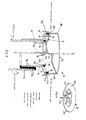
- FIG. 1 there is shown a one way air admittance valve 2 for admitting air into a pipe 3.
- the valve 2 comprises a body portion 4 for fitting to the pipe 3 as shown.
- the valve 2 also comprises a number of air inlet ports 6 in the body portion 4. There may be one, two, three, four or more of the inlet ports 6 as may be desired.
- the valve 2 further comprises sealing means 8 which is longitudinally movable between a first position which is shown on the left side of Figure 1 and in which the sealing means 8 seals the inlet ports 6, and a second position which is shown on the right side of Figure 1 and in which the inlet ports 6 are open for the admittance of air into the pipe 3.
- the valve 2 is such that only one sealing means 8 is employed for sealing all of the inlet ports 6.
- the sealing means 8 is such that it seals at two separate areas 10, 12. These two separate areas 10, 12 are radially spaced apart as shown and they are generally positioned inwardly and outwardly of the inlet ports 6 as shown,
- the inlet ports 6 are formed in a flanged part 14 of the body portion 4.
- the sealing means 8 comprises a rigid sealing disc 16.
- the disc 16 engages with a pair of seals 18,20 which are mounted in the body portion 4 and which are radially spaced apart, whereby the piston 16 effects a seal at the two separate areas 10,12. More specifically, air at the inlet ports 6 is prevented by the seal 20 from passing to the centre of the sealing means 8, and air at the inlet parts 6 is prevented by the seal 18 from passing to the periphery of the sealing means 8.
- the seals 18, 20 are circular lipped seals as shown and they each fit in a groove 26 in the body portion 4.
- the seals 18, 20 each project from their groove 26 inwardly into the body portion 4 as shown in Figure 1.
- the disc 16 has a flange 25 and three webs or spokes 27 which define three apertures 28.
- the disc 16 has peripheral ribs 29 which act as friction reducing guides as the disc 16 moves up and down during operation of the valve 2.
- the disc 16 has a guide member in the form of a guide rod 30.
- the guide rod 30 extends into an aperture 32 formed in a transverse part of the body portion 4.
- the transverse part 34 may be formed by a spoke arrangement 38 similar to the spokes 27 of the piston 8.
- the body portion 4 is closed by a lid 40.
- the lid 40 is a screw lid which fits to the flanged part 14 of the body portion 4. More specifically, the lid 40 screws over the outside of the flanged part 14 by virtue of the illustrated mating screw threads 42. As the lid 40 is screwed down, it engages a top part 44 of the seal 18 to effect a good seal at this point.
- the lid 40 is a relatively flat, lid since it only accommodates the disc 16 and its up and down movement.
- the lid 40 has a first portion 48 and a second and larger diameter portion 50.
- the lid 40 also has a slightly domed top 51.
- the body portion 4 may be provided with a spacer seal in the form of a rubber spacer sleeve 52 for enabling the body portion 4 to fit in a larger pipe 3.
- a spacer seal in the form of a rubber spacer sleeve 52 for enabling the body portion 4 to fit in a larger pipe 3.
- the body portion 4 may fit over a 3 inch (82mm) soil pipe 3 or inside a 4 inch (110mm) soil pipe 3.
- the spacer sleeve 52 has inner and outer ribs 54, 56 respectively.
- the body portion 4, the disc 16 and the lid 40 may be moulded from a plastics material.
- the seals 18, 20 are made from plastics materials of the type usually used in one way air admittance valves for admitting air into pipes.
- the valve 2 shown in Figures 1 and 2 operates such that when flushing of a water closet has not occurred, there will be a positive pressure in the pipe 3.
- the disc 16 will then be in its sealing position as shown in the left hand half of Figure 1.
- a negative pressure or vacuum will occur in the pipe 3 and this might drag water from the sealing trap beneath the toilet bowl in the water closet. This is prevented by air entering the pipe 3 through the inlet ports 6 and through apertures 58 formed in the transverse part 34 of the body portion 4. The air can also pass through the apertures 28 into the lid 40.
- the negative pressure ceases and the piston 6 then returns to its sealing position to stop the escape or unpleasant odours that might otherwise pass up the pipe 3 and escape via the valve 2.
- the valve 2 gives efficient opening of the valve at low pressure, for example as 10mm head of water. At the same time, the valve 2 also gives a good seal to stop smells passing through the valve 2.
- the valve 2 operates to let in a good rush of air and the air passage is not unduly restricted as occurs in some known valves.
- the valve 2 can be installed on multi-storey buildings which are higher than four storeys. With some known valves, they are not able to be installed on multi-storey buildings higher than four storeys since the valves then do not work satisfactorily.
- valves 2 may be made in any desired sizes for fitting to appropriately sized pipes.
- the pipe 3 need not be a soil pipe and it could be, for example, a waste pipe from a sink, bathroom or other area.
- the valves 2 may be fitted to any pipe in which it is required to allow the one way admittance of air.
- valves 2 may be provided with cover means (not shown).
- the cover means may cover a top part of the valves 2 and the cover means may be made from a foamed plastics material such for example as polystyrene.
- the cover means may give some thermal insulation/protection in order to stop the disc 16 freezing up in freezing conditions due to condensation forming in the valves 2.
Landscapes
- Engineering & Computer Science (AREA)
- Structural Engineering (AREA)
- Environmental & Geological Engineering (AREA)
- Health & Medical Sciences (AREA)
- Life Sciences & Earth Sciences (AREA)
- Hydrology & Water Resources (AREA)
- Public Health (AREA)
- Water Supply & Treatment (AREA)
- Self-Closing Valves And Venting Or Aerating Valves (AREA)
- Check Valves (AREA)
Applications Claiming Priority (2)
| Application Number | Priority Date | Filing Date | Title |
|---|---|---|---|
| GB8913009A GB8913009D0 (en) | 1989-06-06 | 1989-06-06 | One way air admittance valve |
| GB8913009 | 1989-06-06 |
Publications (2)
| Publication Number | Publication Date |
|---|---|
| EP0401989A2 true EP0401989A2 (fr) | 1990-12-12 |
| EP0401989A3 EP0401989A3 (fr) | 1991-05-15 |
Family
ID=10657981
Family Applications (1)
| Application Number | Title | Priority Date | Filing Date |
|---|---|---|---|
| EP19900305305 Withdrawn EP0401989A3 (fr) | 1989-06-06 | 1990-05-16 | Vanne de non retour pour l'admission d'air |
Country Status (4)
| Country | Link |
|---|---|
| US (1) | US5048562A (fr) |
| EP (1) | EP0401989A3 (fr) |
| AU (1) | AU5616590A (fr) |
| GB (2) | GB8913009D0 (fr) |
Cited By (8)
| Publication number | Priority date | Publication date | Assignee | Title |
|---|---|---|---|---|
| BE1007220A3 (nl) * | 1993-06-14 | 1995-04-25 | Ericson Kurt Sture Birger | Verluchtingsinrichting voor sanitaire toestellen in gebouw met meerdere verdiepingen. |
| AU706617B2 (en) * | 1995-04-03 | 1999-06-17 | Caroma Industries Limited | Sanitary ware and method of installation |
| FR2816025A1 (fr) * | 2000-10-30 | 2002-05-03 | Claude Jean Marie Frangin | Clapet d'entree d'air |
| RU2234631C2 (ru) * | 1999-02-03 | 2004-08-20 | Курт Стюре Биргер ЭРИКСОН | Впускной воздушный клапан для канализационной системы |
| AU2005239719B1 (en) * | 2005-05-27 | 2006-07-20 | A.D. & R.E. Barker Pty Ltd | Closures for Pipes |
| EP2224066A1 (fr) * | 2009-02-25 | 2010-09-01 | Studor S.A. | Soupape d'admission d'air |
| CN102365410A (zh) * | 2009-04-06 | 2012-02-29 | 斯图多股份有限公司 | 用于生活污水管道系统的高容量进气阀 |
| KR20170073612A (ko) * | 2014-11-07 | 2017-06-28 | 데이코 아이피 홀딩스 엘엘시 | 개선된 시일링 부재를 구비한 체크 밸브 |
Families Citing this family (20)
| Publication number | Priority date | Publication date | Assignee | Title |
|---|---|---|---|---|
| US4901799A (en) * | 1988-06-24 | 1990-02-20 | Grinnell Corporation | Sprinkler head having protuberant ridge valve seat |
| US5273068A (en) * | 1993-04-20 | 1993-12-28 | Duren Gary S | Air admittance valve for resisting high internal pressure |
| SE503815C2 (sv) * | 1995-06-22 | 1996-09-09 | Durgo Ab | Luftningsventil |
| US5971014A (en) * | 1996-09-04 | 1999-10-26 | Duren; Gary S. | Vacuum breaker valve vent fitting clean-out device |
| US6161564A (en) * | 1999-04-06 | 2000-12-19 | Cornwall; Kenneth R. | Fire transmission prevention system |
| USD427286S (en) * | 1999-05-25 | 2000-06-27 | Julius Ballanco | Air admittance valve |
| US6308731B1 (en) * | 1999-06-25 | 2001-10-30 | Itz Corporation | Vent valve |
| US6415816B1 (en) * | 2000-08-31 | 2002-07-09 | Cherne Industries Incorporated | Air admittance valve assembly |
| US7395835B1 (en) | 2005-02-16 | 2008-07-08 | Rectorseal Corporation | Air admittance valve |
| US20060237678A1 (en) * | 2005-04-25 | 2006-10-26 | Lackey Derek J | Metallic Air Admittance Valve |
| US7410608B1 (en) * | 2007-09-19 | 2008-08-12 | Rectorseal Corporation | Methods for manufacturing a diaphragm for an air admittance valve |
| US20100000614A1 (en) | 2008-07-02 | 2010-01-07 | Zahuranec Terry L | Plumbing supply boxes |
| US8136548B2 (en) * | 2008-08-08 | 2012-03-20 | Watertite Products, Inc. | Air admittance valve |
| RU2511774C2 (ru) * | 2011-12-28 | 2014-04-10 | Павел Эдуардович Мельников | Нормально закрытый обратный клапан для установки на вертикальные трубы систем водоснабжения и отопления |
| US9683355B2 (en) | 2014-04-28 | 2017-06-20 | Ips Corporation | Air admittance valve |
| DE102015004532B3 (de) * | 2015-04-02 | 2016-09-29 | Capricorn S. A. | Belüftungsventil für ein Kanalisationsrohr |
| WO2018031728A1 (fr) * | 2016-08-12 | 2018-02-15 | Oatey Co. | Soupape d'admission d'air |
| JP6738298B2 (ja) * | 2017-03-28 | 2020-08-12 | 未来工業株式会社 | 配管構造及び通気弁 |
| JP6718404B2 (ja) * | 2017-03-28 | 2020-07-08 | 未来工業株式会社 | 通気弁及び配管構造 |
| US12305376B2 (en) * | 2023-04-17 | 2025-05-20 | Xmark SP LLC | Air admittance valve |
Family Cites Families (13)
| Publication number | Priority date | Publication date | Assignee | Title |
|---|---|---|---|---|
| DE305264C (fr) * | ||||
| CH191189A (fr) * | 1936-10-01 | 1937-06-15 | Similor Sa | Dispositif de ventilation pour siphon. |
| GB482989A (en) * | 1937-05-11 | 1938-04-08 | Maurice Frederick Richardson | Improvements in valves |
| FR1170964A (fr) * | 1957-04-06 | 1959-01-21 | Anciens Ets Brissonneau & Lotz | Siège perfectionné de soupape |
| US3430648A (en) * | 1966-08-19 | 1969-03-04 | Fruehauf Corp | Vent check valve |
| SE377146B (fr) * | 1973-10-15 | 1975-06-23 | Ba Installationsutveckling Ab | |
| SE433863B (sv) * | 1977-08-31 | 1984-06-18 | Sture Ericson | Automatisk ventilanordning for anslutning till ett sanitert avloppsror |
| NZ196769A (en) * | 1980-04-16 | 1985-03-20 | R M Fairweather | Vacuum breaker valve including annular ring with concentric valve seats |
| GB2112906B (en) * | 1980-12-29 | 1984-12-12 | Mcalpine And Company Limited | Vacuum relief valve |
| BE895071A (fr) * | 1982-11-19 | 1983-03-16 | Ericson Sture | Dispositif de valve a air automatique pour canalisations |
| GB2171781B (en) * | 1985-01-18 | 1989-06-07 | Christopher Erik Andren | Automatic one-way fluid valves |
| GB8703132D0 (en) * | 1987-02-11 | 1987-03-18 | Earl R F | Air admittance valve |
| GB2231391B (en) * | 1989-04-07 | 1993-03-03 | Patrick Daniel Frawley | A one way air admittance valve |
-
1989
- 1989-06-06 GB GB8913009A patent/GB8913009D0/en active Pending
-
1990
- 1990-05-16 GB GB9010911A patent/GB2232461B/en not_active Expired - Fee Related
- 1990-05-16 EP EP19900305305 patent/EP0401989A3/fr not_active Withdrawn
- 1990-05-25 US US07/529,185 patent/US5048562A/en not_active Expired - Fee Related
- 1990-06-01 AU AU56165/90A patent/AU5616590A/en not_active Abandoned
Cited By (17)
| Publication number | Priority date | Publication date | Assignee | Title |
|---|---|---|---|---|
| BE1007220A3 (nl) * | 1993-06-14 | 1995-04-25 | Ericson Kurt Sture Birger | Verluchtingsinrichting voor sanitaire toestellen in gebouw met meerdere verdiepingen. |
| AU706617B2 (en) * | 1995-04-03 | 1999-06-17 | Caroma Industries Limited | Sanitary ware and method of installation |
| RU2234631C2 (ru) * | 1999-02-03 | 2004-08-20 | Курт Стюре Биргер ЭРИКСОН | Впускной воздушный клапан для канализационной системы |
| FR2816025A1 (fr) * | 2000-10-30 | 2002-05-03 | Claude Jean Marie Frangin | Clapet d'entree d'air |
| AU2005239719B1 (en) * | 2005-05-27 | 2006-07-20 | A.D. & R.E. Barker Pty Ltd | Closures for Pipes |
| CN102333922A (zh) * | 2009-02-25 | 2012-01-25 | 斯图多股份有限公司 | 进气阀 |
| WO2010096885A3 (fr) * | 2009-02-25 | 2010-10-21 | Studor S.A. | Moyens de fermeture et d'étanchéité pour vannes d'admission d'air dans des systèmes de tuyau d'eaux usées sanitaires |
| KR20110128186A (ko) * | 2009-02-25 | 2011-11-28 | 스튜도르 에스.에이. | 위생 하수관 시스템의 통기 밸브를 위한 밀폐 및 밀봉 수단 |
| EP2224066A1 (fr) * | 2009-02-25 | 2010-09-01 | Studor S.A. | Soupape d'admission d'air |
| US8567434B2 (en) | 2009-02-25 | 2013-10-29 | Studor S.A. | Closing and sealing means for air admittance valves in sanitary waste water pipe systems |
| CN102333922B (zh) * | 2009-02-25 | 2014-02-05 | 斯图多股份有限公司 | 进气阀 |
| AU2010217207B2 (en) * | 2009-02-25 | 2015-04-02 | Watertite Products, Inc | Air admittance valve |
| KR101659524B1 (ko) * | 2009-02-25 | 2016-09-23 | 스튜도르 에스.에이. | 위생 하수관 시스템의 통기 밸브를 위한 밀폐 및 밀봉 수단 |
| CN102365410A (zh) * | 2009-04-06 | 2012-02-29 | 斯图多股份有限公司 | 用于生活污水管道系统的高容量进气阀 |
| KR20170073612A (ko) * | 2014-11-07 | 2017-06-28 | 데이코 아이피 홀딩스 엘엘시 | 개선된 시일링 부재를 구비한 체크 밸브 |
| JP2017537278A (ja) * | 2014-11-07 | 2017-12-14 | デイコ アイピー ホールディングス, エルエルシーDayco Ip Holdings, Llc | 改良されたシーリング部材を備えたチェックバルブ |
| EP3215770A4 (fr) * | 2014-11-07 | 2018-07-11 | Dayco IP Holdings, LLC | Clapet antiretour à élément d'étanchéité amélioré |
Also Published As
| Publication number | Publication date |
|---|---|
| US5048562A (en) | 1991-09-17 |
| GB8913009D0 (en) | 1989-07-26 |
| GB2232461A (en) | 1990-12-12 |
| GB2232461B (en) | 1993-12-22 |
| EP0401989A3 (fr) | 1991-05-15 |
| AU5616590A (en) | 1990-12-13 |
| GB9010911D0 (en) | 1990-07-04 |
Similar Documents
| Publication | Publication Date | Title |
|---|---|---|
| US5048562A (en) | One way air admittance valve | |
| US4494255A (en) | Ventilated toilet device | |
| US3605132A (en) | Automatic plumbing vent valve | |
| US8505123B2 (en) | Ventilated toilet | |
| US3938201A (en) | Ventilator for a toilet bowl | |
| US2777137A (en) | Closet bowl ventilator | |
| US5167039A (en) | Toilet assembly | |
| US5005222A (en) | Toilet assembly | |
| CA2699613C (fr) | Toilette ventilee | |
| US2724840A (en) | Ventilated toilet bowl | |
| GB1368835A (en) | Toilet | |
| US5287563A (en) | Hygienic urinal | |
| AU2016277635A2 (en) | Toilet ventilation apparatus | |
| US4704747A (en) | Self-contained bathroom unit | |
| US20220034076A1 (en) | Ventilated toilet | |
| JPH0853910A (ja) | 床排水用のトラップ | |
| GB2231391A (en) | A one way air admittance valve | |
| JP5269401B2 (ja) | 桝 | |
| GB2268520A (en) | Vented toilet seat | |
| JPH0638944Y2 (ja) | 便 器 | |
| JP2578451Y2 (ja) | 吸気弁 | |
| US2127184A (en) | Waste system | |
| GB2076443A (en) | Water closet cistern overflow | |
| GB2236376A (en) | A one way air admittance valve | |
| IE54192B1 (en) | Ventilating apparatus for a toilet |
Legal Events
| Date | Code | Title | Description |
|---|---|---|---|
| PUAI | Public reference made under article 153(3) epc to a published international application that has entered the european phase |
Free format text: ORIGINAL CODE: 0009012 |
|
| AK | Designated contracting states |
Kind code of ref document: A2 Designated state(s): AT BE CH DE DK ES FR GR IT LI LU NL SE |
|
| PUAL | Search report despatched |
Free format text: ORIGINAL CODE: 0009013 |
|
| AK | Designated contracting states |
Kind code of ref document: A3 Designated state(s): AT BE CH DE DK ES FR GR IT LI LU NL SE |
|
| STAA | Information on the status of an ep patent application or granted ep patent |
Free format text: STATUS: THE APPLICATION IS DEEMED TO BE WITHDRAWN |
|
| 18D | Application deemed to be withdrawn |
Effective date: 19911118 |