EP0402086B1 - Contact dans une prise pour un composant électrique - Google Patents
Contact dans une prise pour un composant électrique Download PDFInfo
- Publication number
- EP0402086B1 EP0402086B1 EP90306077A EP90306077A EP0402086B1 EP 0402086 B1 EP0402086 B1 EP 0402086B1 EP 90306077 A EP90306077 A EP 90306077A EP 90306077 A EP90306077 A EP 90306077A EP 0402086 B1 EP0402086 B1 EP 0402086B1
- Authority
- EP
- European Patent Office
- Prior art keywords
- contact
- terminal
- contact portion
- contact element
- portions
- Prior art date
- Legal status (The legal status is an assumption and is not a legal conclusion. Google has not performed a legal analysis and makes no representation as to the accuracy of the status listed.)
- Expired - Lifetime
Links
- 238000003780 insertion Methods 0.000 claims description 10
- 230000037431 insertion Effects 0.000 claims description 10
- 230000002452 interceptive effect Effects 0.000 claims description 2
- 239000004020 conductor Substances 0.000 claims 1
- 238000006073 displacement reaction Methods 0.000 claims 1
- 230000005540 biological transmission Effects 0.000 description 5
- 230000000916 dilatatory effect Effects 0.000 description 5
- 238000005452 bending Methods 0.000 description 4
- 239000007769 metal material Substances 0.000 description 3
- 238000004519 manufacturing process Methods 0.000 description 2
- 239000002994 raw material Substances 0.000 description 2
- 230000002146 bilateral effect Effects 0.000 description 1
- 230000002349 favourable effect Effects 0.000 description 1
- 238000012986 modification Methods 0.000 description 1
- 230000004048 modification Effects 0.000 description 1
Images




Classifications
-
- H—ELECTRICITY
- H01—ELECTRIC ELEMENTS
- H01R—ELECTRICALLY-CONDUCTIVE CONNECTIONS; STRUCTURAL ASSOCIATIONS OF A PLURALITY OF MUTUALLY-INSULATED ELECTRICAL CONNECTING ELEMENTS; COUPLING DEVICES; CURRENT COLLECTORS
- H01R13/00—Details of coupling devices of the kinds covered by groups H01R12/70 or H01R24/00 - H01R33/00
- H01R13/02—Contact members
- H01R13/15—Pins, blades or sockets having separate spring member for producing or increasing contact pressure
-
- H—ELECTRICITY
- H01—ELECTRIC ELEMENTS
- H01R—ELECTRICALLY-CONDUCTIVE CONNECTIONS; STRUCTURAL ASSOCIATIONS OF A PLURALITY OF MUTUALLY-INSULATED ELECTRICAL CONNECTING ELEMENTS; COUPLING DEVICES; CURRENT COLLECTORS
- H01R13/00—Details of coupling devices of the kinds covered by groups H01R12/70 or H01R24/00 - H01R33/00
- H01R13/02—Contact members
- H01R13/10—Sockets for co-operation with pins or blades
- H01R13/11—Resilient sockets
- H01R13/112—Resilient sockets forked sockets having two legs
-
- H—ELECTRICITY
- H05—ELECTRIC TECHNIQUES NOT OTHERWISE PROVIDED FOR
- H05K—PRINTED CIRCUITS; CASINGS OR CONSTRUCTIONAL DETAILS OF ELECTRIC APPARATUS; MANUFACTURE OF ASSEMBLAGES OF ELECTRICAL COMPONENTS
- H05K7/00—Constructional details common to different types of electric apparatus
- H05K7/02—Arrangements of circuit components or wiring on supporting structure
- H05K7/10—Plug-in assemblages of components, e.g. IC sockets
- H05K7/1053—Plug-in assemblages of components, e.g. IC sockets having interior leads
- H05K7/1076—Plug-in assemblages of components, e.g. IC sockets having interior leads co-operating by sliding
- H05K7/1084—Plug-in assemblages of components, e.g. IC sockets having interior leads co-operating by sliding pin grid array package carriers
Definitions
- This invention relates to a contact which is effectively used in a socket for an electric part such as an IC socket or the like, and particularly to a contact, in which contact elements of the contact are forcedly dilated by a lateral movement in one direction of a moving plate provided on a socket body so that terminals of the electric part can be inserted and removed with no load, and the dilating force is canceled by a lateral movement in the other direction of the moving plate so that the terminals of the electric part can be brought into contact with contact elements of the contact.
- a conventional contact of this type has a pair of elongated contact elements 11a and 11b disposed in such a manner as that plate surfaces (outer surfaces of a raw material) thereof are faced with each other, contacting portions 11c and 11d being formed in the vicinity of the free ends of the contacting elements 11a and 11b so that a terminal of an electric part can be pinched between the plate surfaces of the contacting portions 11c and 11d, the leading end of the contact element 11a extending upward beyond the leading end of the other contact element 11b to form a pressure receiving portion 11e.
- This conventional contact 11 is formed in such a manner as that the contact elements 11a and 11b, as shown in Fig. 12, are developed and perforated in that state, and then folded back into two along a connecting portion to form the afore-mentioned facing state.
- the contact 11 When in operation, the contact 11 is held by a socket body and the pressure receiving portion is engaged with a lower surface of a moving plate which horizontally moves along the upper surface of the socket body, so that a pushing force is applied to the pressure receiving portion 11e of the contact 11 by a lateral movement in one direction of the moving plate to dilate the contacting portions 11c and 11d and an electric part is inserted therein and removed therefrom with no load, and on the other hand, the dilating force is canceled by a lateral movement in the other direction of the moving plate, thereby to realize the above-mentioned pinching contact.
- this conventional contact requires a comparatively complicated bending treatment and a large amount of a metallic material is consumed for a single contact.
- the productivity of the contact is inferior, dimensional accuracy thereof is difficult to obtain, and the contact becomes expensive.
- the present invention has been accomplished in view of the above problems.
- the invention provides a contact in accordance with Claim 1.
- the invention also provides an assembly of a socket body, a contact and a movable block, in accordance with Claim 2.
- the contact is planted in a socket body, and an end portion of the inverted general L-shaped contact element of the contact is engaged with the moving plate which is laterally movably disposed on an upper surface of the socket body.
- the moving plate By a lateral movement of the moving plate, the reversed generally L-shaped contact is dilated in the perforating direction against its elasticity and a terminal of an electric part is inserted with no load between the other contact element and the inverted generally L-shaped contact element.
- the inverted generally L-shaped contact piece is restored to pinch the terminal in the perforating direction.
- the numeral 1 is a contact of the present invention.
- the contact 1 is formed by perforating a belt-like metallic material.
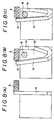
- fork-like first and second elongated contact elements 1a and 1b which are faced with respect to each other at the sheared surfaces and extends in parallel relation are formed.
- the first and second elongated contact elements 1a and 1b are connected with each other at root portions thereof and provided with a contacting portion, respectively, at leading ends thereof.
- the contacting portion of the first elongated contact element 1a is formed by an inverted generally L-shaped contact element 1c projecting in the facing direction which is formed by being bent by means of perforation.
- the both contacting portions are arranged such that one contacting portion is located in an upper position and the other contacting portion is located in a lower position, and both the contacting portions are displaced in the perforating direction without interfering with each other.
- the first elongated contact element 1a, the second elongated contact element 1b, the inverted generally L-shaped contact element 1c and the contacting portion are arranged in a relation of upper and lower positions in a same plane. That is, the contact elements 1c and 1e are arranged such that the sheared surfaces formed by perforation are vertically faced with each other. Also, the inverted generally L-shaped contact element 1c and the contact element 1e are arranged in such a manner as to be displaced in phase in the perforating direction within the thickness of the sheared surfaces formed by perforation.
- the first elongated contact element 1a is displaced in phase in the perforating direction by applying a pushing force from an outer surface (outer surface of a raw material provided by perforation) side perpendicular to the perforating direction with respect to the inverted generally L-shaped contact element 1c, and at the same time, the inverted generally L-shaped contact element 1c is twist displaced in the perforating direction about the first elongated contact element 1a to form a terminal insertion gap directing in the perforating direction between an outer surface of the second elongated contact piece 1b and the inverted generally L-shaped contact element 1c.
- a pressure receiving portion 1d is formed by a free end of the inverted generally L-shaped contact element 1c.
- the free end of the inverted generally L-shaped contact element 1c projects backward beyond the contacting portion at the leading end of the second elongated contact element 1b to form the pressure receiving portion 1d.
- the second contact element 1b is provided at the leading end thereof with the contact element 1e projecting in an inverted generally L-shape toward the first elongated contact element 1a.
- the contact elements 1c and 1e are disposed in such a manner as to be in upper and lower positions.
- the contact element 1c is displaced in the perforating direction to form a no load insertion gap 10 directing in the perforating direction between the contact element 1e and contact element 1c.
- the contact element 1c is restored to its original position. In this way, the terminal 9 is pinched in a vertically displaced position on the axial line of the terminal 9.
- first and second elongated contact elements 1a and 1b are provided at a connected portion 1f with a press-fit portion 1g for fixing to the socket body.
- an external terminal 1h is formed in such a manner as to penetrate the socket body 2 and project downward below the socket body 2 in order to be connected with a printed board, etc.
- the external terminal 1h extends in a same plane as the first and second elongated contact elements 1a and 1b.
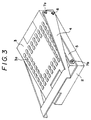
- the contact 1 such constructed is planted and fixed to the socket body 2 similar to one to which the conventional contact 11 is planted using the press-fit portion 1g. Also, a moving plate 3 for horizontally moving along the upper surface of the socket body 2 is provided. The terminal 9 of the electric part 8 placed on the upper surface of the moving plate 3 is inserted into the terminal insertion hole 3a formed in the moving plate 3 in order to be contacted with the contact 1. Furthermore, the pressure receiving portion 1d formed on the leading end of the inverted generally L-shaped contact element 1c of the first elongated contact element 1a is engaged with the lower surface of the moving plate 3 (see Fig. 4).
- a root end of an operating lever 4 is pivotally attached to one end of the moving plate 3 through a supporting shaft 6.
- the moving plate 3 also has a transmission lever 5 one end of which is pivotally attached to the other end of the moving plate 3.
- the other end of the transmission lever 5 and the root end of the operating lever 4 is pivotally attached to the moving plate 3 through the transmission shaft 7a.
- the lateral movement means for the moving plate 3 is formed.
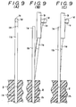
- the terminal 9 of the electric part 8 is inserted into the terminal insertion hole 3a formed in the moving plate 3 in order to be inserted into the terminal insertion gap 10 with no load. That is, the terminal 9 is inserted between the outer surface of the inverted generally L-shaped contact element 1c and the contact element 1e of the second elongated contact element 1b.
- the operating lever 4 is pivoted about the supporting shaft 6 again to exert a lateral moving force to the moving plate 3 through the transmission shafts 7a and 7b.
- a pushing force is exerted to the pressure receiving portion 1d of the contact 1 to forcedly dilate the first elongated contact element 1a against its elasticity and a pinching force exerted to the terminal 9 of the electric part 9 is removed to attain a released state.
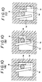
- both the first elongated contact element 1a and the second elongated contact element 1b or the selected one of the first or second elongated contact element 1a or 1b are subjected to a small amount of bending treatment in the perforating direction, and when looked from above, the inverted generally L shaped contact element 1c as a contacting portion of the first contact element 1a and the contact element 1e of the second elongated contact element are arranged to be faced with each other within the thickness of said contact element so that the terminal is pinched in a displaced position shown by the solid line from a position shown by the imaginary line, or otherwise, the inverted generally L-shaped contact element 1c and the contact element 1e are arranged in such a manner as to be displaced in phase in the perforating direction beyond the thickness of the sheared surfaces formed by
- the first elongated contact element 1a is displaced in phase in the direction as shown by the solid line in Fig. 10B or the first elongated contact element 1a is displaced in phase in the opposite direction as shown in Fig. 10C to attain the pinching contact.
- the pinching force by the contact elements 1c and 1e becomes strongest in the embodiment shown in Fig. 10C.
- the inverted generally L-shaped contact element is dilated against its elasticity in the perforating direction by a pushing force, etc. through the moving plate disposed on the socket body in such a manner as to be able to laterally move along the upper surface thereof and a terminal of an electric part can be inserted with no load into a gap formed between the inverted generally L-shaped contact element and the other contact element, and by removing the dilating force, the inverted generally L-shaped element is restored to its original position to realize a favorable pinching contact of the terminal in position vertically displaced from the axial line.
- This function can be effectively realized in a contact form which is given by the afore-mentioned perforation.
- a contact for the use of zero insertion force which does not required such a complicated bending work as in the conventional contact, the consumption of metallic material for manufacturing a single contact is reduced as much as possible to improve the yield of production, excellent in productivity, high in dimensional accuracy and inexpensive.
Landscapes
- Engineering & Computer Science (AREA)
- Microelectronics & Electronic Packaging (AREA)
- Connecting Device With Holders (AREA)
- Coupling Device And Connection With Printed Circuit (AREA)
Claims (3)
- Contact (1) pour insertion dans une prise d'un composant électrique et pour y recevoir une borne, un premier élément de contact allongé (1a) et un deuxième élément de contact allongé (1b) faits en matériau conducteur élastique, lesdits éléments de contact (1a, 1b) étant reliés entre eux à des premierès de leurs extrémités respectives pour former une terminaison de contact pour insertion dans une prise, et comportant à leurs autres extrémités une première et une deuxième parties de contact (1c, 1e) respectives qui sont allongées transversalement par rapport auxdits éléments de contact (1a, 1b) et chacune s'étendant vers l'autre élément de contact allongé, ladite première partie de contact (1c) sur ledit premier élément de contact (1a) étant plus éloignée desdites premierès extrémités dans le sens de l'allongement desdits éléments de contact (1a, 1b) que ladite deuxième partie de contact (1e) dudit deuxième élément de contact (1b), lesdites parties de contact (1c, 1e) étant positionnées pour pouvoir être déplacées de manière élastique dans une direction latérale par rapport à la fois à la direction d'allongement desdits éléments de contact et auxdites parties de contact par lequel moyen lesdites parties de contact (1c, 1e) peuvent être séparées de manière élastique dans ladite direction latérale pour former entre elles une ouverture (10) de réception de terminaison dans laquelle une terminaison peut être insérée sans application de force, et peuvent par la suite se déplacer ensemble pour serrer entre elles la terminaison, caractérisé en ce que lesdits premier et deuxième éléments de contact (1a, 1b) sont disposés en relation parallèle espacée dans un plan uniforme, et en ce que lesdites première et deuxième parties de contact (1c, 1e) sont disposées dans une relation opposée espacée dans ledit plan uniforme avec la surface inférieure de ladite première partie de contact (1c) et la surface supérieure de ladite deuxième partie de contact (1e) se faisant vis-à-vis et avec ladite première partie de contact dépassant par rapport à ladite deuxième partie de contact (1e) dans la direction de l'allongement de ladite première partie de contact (1c), la portion de ladite première partie de contact dépassant par rapport à ladite deuxième partie de contact étant une portion de réception de pression (1d), lesdites parties de contact (1c, 1e) pouvant être déplacées l'une par rapport à l'autre dans une direction latérale par rapport à la fois à ladite direction d'allongement desdits éléments de contact et auxdites parties de contact et transversalement audit plan uniforme sans faire obstacle l'une à l'autre, d'une manière prédominante par un mouvement de torsion de la première partie de contact (1c) autour dudit premier élément de contact (1a) pour former ladite ouverture (10) de réception de terminaison entre lesdites première et deuxième parties de contact (1c, 1e), quand une force est appliquée à ladite portion de réception de pression (1d).
- Assemblage comprenant un corps de prise (2) comportant en lui au moins un enfoncement de réception de contact, un contact (1) selon la revendication 1 pour recevoir une terminaison et positionné dans ledit enfoncement, et un bloc mobile (3) sur ledit corps de prise (2) qui est mobile dans ladite direction latérale qui est normale à la direction de contact entre une terminaison et le contact (1), quand une terminaison est insérée lors de son utilisation dans le contact, et comportant sur lui une partie d'engagement avec le contact disposée pour engager ladite portion de réception de pression (1d); dans lequel ledit bloc est mobile dans ladite direction latérale pour appliquer une force à ladite portion de réception de pression (1d) pour déplacer ladite première partie de contact (1c) par rapport à ladite deuxième partie de contact (1e) pour permettre la réception d'une terminaison entre lesdites première et deuxième parties de contact (1c, 1e).
- Assemblage selon la revendication 2 dans lequel ladite deuxième partie de contact (1e) est normalement disposée dans ledit corps de prise (2) de sorte qu'il est déplacé par rapport à la première partie de contact (1c) qui se trouve sur un côté de ladite deuxième partie de contact (1e) et qui est déplacée de l'autre côté de ladite deuxième partie de contact (1e) lors du mouvement dudit bloc (3) dans ladite direction latérale (fig. 10(c)).
Applications Claiming Priority (2)
| Application Number | Priority Date | Filing Date | Title |
|---|---|---|---|
| JP147430/89 | 1989-06-08 | ||
| JP1147430A JP2599791B2 (ja) | 1989-06-08 | 1989-06-08 | 電気部品用ソケットにおけるコンタクト |
Publications (3)
| Publication Number | Publication Date |
|---|---|
| EP0402086A2 EP0402086A2 (fr) | 1990-12-12 |
| EP0402086A3 EP0402086A3 (fr) | 1991-01-23 |
| EP0402086B1 true EP0402086B1 (fr) | 1995-11-15 |
Family
ID=15430143
Family Applications (1)
| Application Number | Title | Priority Date | Filing Date |
|---|---|---|---|
| EP90306077A Expired - Lifetime EP0402086B1 (fr) | 1989-06-08 | 1990-06-04 | Contact dans une prise pour un composant électrique |
Country Status (6)
| Country | Link |
|---|---|
| EP (1) | EP0402086B1 (fr) |
| JP (1) | JP2599791B2 (fr) |
| KR (1) | KR910002049A (fr) |
| CA (1) | CA2018328A1 (fr) |
| DE (1) | DE69023549T2 (fr) |
| MY (1) | MY105778A (fr) |
Families Citing this family (1)
| Publication number | Priority date | Publication date | Assignee | Title |
|---|---|---|---|---|
| US5466169A (en) * | 1994-08-03 | 1995-11-14 | Lai; Kuang-Chih | Zero insertion force socket |
Family Cites Families (2)
| Publication number | Priority date | Publication date | Assignee | Title |
|---|---|---|---|---|
| US3763459A (en) * | 1971-06-17 | 1973-10-02 | Textool Prod Inc | Plug-in type sockets for testing semiconductors |
| US4468072A (en) * | 1981-12-17 | 1984-08-28 | Thomas & Betts Corporation | Multi-pin zero insertion force connector |
-
1989
- 1989-06-08 JP JP1147430A patent/JP2599791B2/ja not_active Expired - Fee Related
-
1990
- 1990-06-04 DE DE69023549T patent/DE69023549T2/de not_active Expired - Fee Related
- 1990-06-04 EP EP90306077A patent/EP0402086B1/fr not_active Expired - Lifetime
- 1990-06-05 CA CA002018328A patent/CA2018328A1/fr not_active Abandoned
- 1990-06-05 MY MYPI90000933A patent/MY105778A/en unknown
- 1990-06-08 KR KR1019900008428A patent/KR910002049A/ko not_active Abandoned
Also Published As
| Publication number | Publication date |
|---|---|
| JPH0311572A (ja) | 1991-01-18 |
| JP2599791B2 (ja) | 1997-04-16 |
| KR910002049A (ko) | 1991-01-31 |
| EP0402086A2 (fr) | 1990-12-12 |
| DE69023549T2 (de) | 1996-07-25 |
| DE69023549D1 (de) | 1995-12-21 |
| CA2018328A1 (fr) | 1990-12-08 |
| MY105778A (en) | 1995-01-30 |
| EP0402086A3 (fr) | 1991-01-23 |
Similar Documents
| Publication | Publication Date | Title |
|---|---|---|
| US5059135A (en) | Contact in a socket for an electric part | |
| US6315621B1 (en) | Electrical connector contact element having multi-contact points to come into contact with a single mating contact element with independent contacting forces | |
| US5647755A (en) | Electrical connector | |
| EP1632011B1 (fr) | Connecteur électrique | |
| US20020079202A1 (en) | Switch exhibiting non-unidirectional displacement | |
| US6561843B1 (en) | FPC connector | |
| CA1265221A (fr) | Borne de connexion electrique pour connecteur | |
| EP0379219B1 (fr) | Connecteur électrique | |
| US6139348A (en) | Electric connector with an elastically deformable contact pin | |
| US6155864A (en) | Connector locking structure | |
| CA1182538A (fr) | Connecteur fixable a une carte de circuits imprimes pour cable plat | |
| JPH08273710A (ja) | 電気接触素子 | |
| US6565376B2 (en) | Flat cable terminal | |
| JP2000106235A (ja) | コネクタ装置 | |
| US5871369A (en) | Connector | |
| US6086401A (en) | Terminal having low insertion force | |
| US4918813A (en) | Method of shaping plug receptacle | |
| AU4861090A (en) | Low insertion force connector and electrical contact therefor | |
| IE801717L (en) | Connector for connecting conductors on a flat cable to¹conductors on a substrate | |
| EP0402086A2 (fr) | Contact dans une prise pour un composant électrique | |
| EP0006725B1 (fr) | Connecteur électrique pour relier un câble plat à un substrat | |
| US4983128A (en) | Bus bar for making electrical taps | |
| CA1107831A (fr) | Connecteur electrique avec ejecteur a ressort | |
| JPH054226Y2 (fr) | ||
| JPH0660964U (ja) | 差込形接続端子 |
Legal Events
| Date | Code | Title | Description |
|---|---|---|---|
| PUAI | Public reference made under article 153(3) epc to a published international application that has entered the european phase |
Free format text: ORIGINAL CODE: 0009012 |
|
| PUAL | Search report despatched |
Free format text: ORIGINAL CODE: 0009013 |
|
| AK | Designated contracting states |
Kind code of ref document: A2 Designated state(s): DE FR GB IT |
|
| AK | Designated contracting states |
Kind code of ref document: A3 Designated state(s): DE FR GB IT |
|
| 17P | Request for examination filed |
Effective date: 19910318 |
|
| 17Q | First examination report despatched |
Effective date: 19930921 |
|
| RAP1 | Party data changed (applicant data changed or rights of an application transferred) |
Owner name: YAMAICHI ELECTRONICS CO., LTD. |
|
| GRAA | (expected) grant |
Free format text: ORIGINAL CODE: 0009210 |
|
| AK | Designated contracting states |
Kind code of ref document: B1 Designated state(s): DE FR GB IT |
|
| PG25 | Lapsed in a contracting state [announced via postgrant information from national office to epo] |
Ref country code: IT Free format text: LAPSE BECAUSE OF FAILURE TO SUBMIT A TRANSLATION OF THE DESCRIPTION OR TO PAY THE FEE WITHIN THE PRE;WARNING: LAPSES OF ITALIAN PATENTS WITH EFFECTIVE DATE BEFORE 2007 MAY HAVE OCCURRED AT ANY TIME BEFORE 2007. THE CORRECT EFFECTIVE DATE MAY BE DIFFERENT FROM THE ONE RECORDED.SCRIBED TIME-LIMIT Effective date: 19951115 Ref country code: FR Effective date: 19951115 |
|
| REF | Corresponds to: |
Ref document number: 69023549 Country of ref document: DE Date of ref document: 19951221 |
|
| EN | Fr: translation not filed | ||
| PGFP | Annual fee paid to national office [announced via postgrant information from national office to epo] |
Ref country code: GB Payment date: 19960520 Year of fee payment: 7 |
|
| PGFP | Annual fee paid to national office [announced via postgrant information from national office to epo] |
Ref country code: DE Payment date: 19960626 Year of fee payment: 7 |
|
| PLBE | No opposition filed within time limit |
Free format text: ORIGINAL CODE: 0009261 |
|
| STAA | Information on the status of an ep patent application or granted ep patent |
Free format text: STATUS: NO OPPOSITION FILED WITHIN TIME LIMIT |
|
| 26N | No opposition filed | ||
| PG25 | Lapsed in a contracting state [announced via postgrant information from national office to epo] |
Ref country code: GB Free format text: LAPSE BECAUSE OF NON-PAYMENT OF DUE FEES Effective date: 19970604 |
|
| GBPC | Gb: european patent ceased through non-payment of renewal fee |
Effective date: 19970604 |
|
| PG25 | Lapsed in a contracting state [announced via postgrant information from national office to epo] |
Ref country code: DE Free format text: LAPSE BECAUSE OF NON-PAYMENT OF DUE FEES Effective date: 19980303 |