EP0402131B1 - Installation frigorifique avec accumulateur thermique supplémentaire - Google Patents
Installation frigorifique avec accumulateur thermique supplémentaire Download PDFInfo
- Publication number
- EP0402131B1 EP0402131B1 EP90306184A EP90306184A EP0402131B1 EP 0402131 B1 EP0402131 B1 EP 0402131B1 EP 90306184 A EP90306184 A EP 90306184A EP 90306184 A EP90306184 A EP 90306184A EP 0402131 B1 EP0402131 B1 EP 0402131B1
- Authority
- EP
- European Patent Office
- Prior art keywords
- thermal storage
- working fluid
- cooling
- storage means
- evaporator
- Prior art date
- Legal status (The legal status is an assumption and is not a legal conclusion. Google has not performed a legal analysis and makes no representation as to the accuracy of the status listed.)
- Expired - Lifetime
Links
- 238000001816 cooling Methods 0.000 title claims abstract description 125
- 230000000153 supplemental effect Effects 0.000 title claims abstract description 14
- 239000012530 fluid Substances 0.000 claims abstract description 91
- 239000007788 liquid Substances 0.000 claims abstract description 43
- 238000004378 air conditioning Methods 0.000 claims description 28
- XLYOFNOQVPJJNP-UHFFFAOYSA-N water Substances O XLYOFNOQVPJJNP-UHFFFAOYSA-N 0.000 claims description 22
- 239000012782 phase change material Substances 0.000 claims description 19
- 239000003507 refrigerant Substances 0.000 claims description 18
- 238000000034 method Methods 0.000 claims description 11
- 150000003839 salts Chemical class 0.000 claims description 3
- 230000005496 eutectics Effects 0.000 claims 1
- 238000007710 freezing Methods 0.000 description 6
- 230000008014 freezing Effects 0.000 description 6
- 238000010586 diagram Methods 0.000 description 4
- 230000005611 electricity Effects 0.000 description 4
- 238000004513 sizing Methods 0.000 description 4
- 230000008901 benefit Effects 0.000 description 3
- 239000000498 cooling water Substances 0.000 description 3
- 238000002844 melting Methods 0.000 description 3
- 239000000203 mixture Substances 0.000 description 3
- 230000008569 process Effects 0.000 description 3
- 238000001704 evaporation Methods 0.000 description 2
- 230000008018 melting Effects 0.000 description 2
- 230000009467 reduction Effects 0.000 description 2
- 238000005057 refrigeration Methods 0.000 description 2
- 229920006395 saturated elastomer Polymers 0.000 description 2
- WYTGDNHDOZPMIW-RCBQFDQVSA-N alstonine Natural products C1=CC2=C3C=CC=CC3=NC2=C2N1C[C@H]1[C@H](C)OC=C(C(=O)OC)[C@H]1C2 WYTGDNHDOZPMIW-RCBQFDQVSA-N 0.000 description 1
- 230000015572 biosynthetic process Effects 0.000 description 1
- 238000009835 boiling Methods 0.000 description 1
- 230000008859 change Effects 0.000 description 1
- 230000002301 combined effect Effects 0.000 description 1
- 230000006835 compression Effects 0.000 description 1
- 238000007906 compression Methods 0.000 description 1
- 230000007797 corrosion Effects 0.000 description 1
- 238000005260 corrosion Methods 0.000 description 1
- 230000007423 decrease Effects 0.000 description 1
- 230000001419 dependent effect Effects 0.000 description 1
- 230000000694 effects Effects 0.000 description 1
- 238000009429 electrical wiring Methods 0.000 description 1
- 238000005265 energy consumption Methods 0.000 description 1
- 230000008020 evaporation Effects 0.000 description 1
- 238000009434 installation Methods 0.000 description 1
- 230000007246 mechanism Effects 0.000 description 1
Images


Classifications
-
- F—MECHANICAL ENGINEERING; LIGHTING; HEATING; WEAPONS; BLASTING
- F25—REFRIGERATION OR COOLING; COMBINED HEATING AND REFRIGERATION SYSTEMS; HEAT PUMP SYSTEMS; MANUFACTURE OR STORAGE OF ICE; LIQUEFACTION SOLIDIFICATION OF GASES
- F25D—REFRIGERATORS; COLD ROOMS; ICE-BOXES; COOLING OR FREEZING APPARATUS NOT OTHERWISE PROVIDED FOR
- F25D16/00—Devices using a combination of a cooling mode associated with refrigerating machinery with a cooling mode not associated with refrigerating machinery
-
- F—MECHANICAL ENGINEERING; LIGHTING; HEATING; WEAPONS; BLASTING
- F24—HEATING; RANGES; VENTILATING
- F24F—AIR-CONDITIONING; AIR-HUMIDIFICATION; VENTILATION; USE OF AIR CURRENTS FOR SCREENING
- F24F5/00—Air-conditioning systems or apparatus not covered by F24F1/00 or F24F3/00, e.g. using solar heat or combined with household units such as an oven or water heater
- F24F5/0007—Air-conditioning systems or apparatus not covered by F24F1/00 or F24F3/00, e.g. using solar heat or combined with household units such as an oven or water heater cooling apparatus specially adapted for use in air-conditioning
- F24F5/0017—Air-conditioning systems or apparatus not covered by F24F1/00 or F24F3/00, e.g. using solar heat or combined with household units such as an oven or water heater cooling apparatus specially adapted for use in air-conditioning using cold storage bodies, e.g. ice
-
- Y—GENERAL TAGGING OF NEW TECHNOLOGICAL DEVELOPMENTS; GENERAL TAGGING OF CROSS-SECTIONAL TECHNOLOGIES SPANNING OVER SEVERAL SECTIONS OF THE IPC; TECHNICAL SUBJECTS COVERED BY FORMER USPC CROSS-REFERENCE ART COLLECTIONS [XRACs] AND DIGESTS
- Y02—TECHNOLOGIES OR APPLICATIONS FOR MITIGATION OR ADAPTATION AGAINST CLIMATE CHANGE
- Y02E—REDUCTION OF GREENHOUSE GAS [GHG] EMISSIONS, RELATED TO ENERGY GENERATION, TRANSMISSION OR DISTRIBUTION
- Y02E60/00—Enabling technologies; Technologies with a potential or indirect contribution to GHG emissions mitigation
- Y02E60/14—Thermal energy storage
Definitions
- the present invention relates generally to an air cooling system, and more particularly, to an air cooling system with the capability to provide supplemental cooling through the use of a thermal storage device.
- an air cooling or air conditioning system that can provide desired air conditioning to a commercial building during normal warm outdoor conditions and yet also have a sufficient reserve supply to provide adequate air conditioning to the building during peak conditions during unusually warm, sunny and humid outdoor conditions.
- One way to provide such an air conditioning system is to size the system such that the peak demand can be mechanically met by the various system components.
- This is undesirable from a installation cost point of view due to the capital investment required for system components such as compressors, condensers, interconnecting piping and electrical wiring and switchgear.
- Another consideration is the relatively high cost to operate such systems due to the demand charge that may be levied by the electrical authorities dependent on the maximum instantaneous electrical demand of the compressor when in fact the maximum electrical draw is only required for a relatively few days during the cooling season.
- the operating cost is an even greater consideration in regions where the authorities penalize units of electricity consumed in the afternoon with time-of-day pricing.
- thermal storage when applied to cooling systems actually refers to the storage of cooling capacity, usually in the form of a frozen phase change material which is utilized to further chill a liquid used in the air cooling or air conditioning system.
- thermal storage is set forth in U.S. Pat. No. 4,720,984. This patent recognizes the reduced cooling needs for a building during nighttime hours and discloses the use of the chilled water outlet of a cooling tower to freeze a phase change material during such nighttime hours.
- the phase change material is said to be included in a storage tank containing packages of a salt composition phase change material having a freezing-melting point above the temperature of the chilled liquid emerging from the cooling tower.
- the phase change material can be remelted during the following peak building cooling demand by providing additional chilling to the water exiting the cooling tower by allowing such water to pass through the tank in close proximity to the packaged phase change material and exiting from the tank.
- the phase change material is accordingly remelted and assists the mechanical chiller in the cooling of the water in the building loop.
- Such system requires the use of an intermediate water loop, the major components of which are a cooling tower, a chiller, and a thermal storage tank, to transfer the cooling effect from the cooling equipment to the building.
- US Patent No. 4,637,219 sets forth a system, as discussed in the preamble of claim 1, utilizing thermal storage which does not require the use of an intermediate water loop.
- This system achieves a reduction in peak energy consumption by using the stored "cool" thermal energy to condense the high pressure refrigerant during the periods of high outside temperatures.
- the required power for the air conditioning system is reduced and peak energy reduction is accomplished.
- an object of the present invention to provide an air cooling system having supplemental thermal storage capacity which does not require the use of an intermediate water loop or a liquid overfeed system.
- the invention provides a cooling system comprising a compressor means having an inlet and an outlet for a working fluid, a condenser means having an inlet and an outlet for a working fluid, an evaporator means having an inlet and an outlet for a working fluid, and a thermal storage means having an inlet and an outlet for a working fluid, the compressor means outlet being connected to the condenser means inlet, and the system further comprising means for selecting one of three modes of operation, the modes comprising: a first mode wherein the condenser means outlet is connected to the evaporator means inlet bypassing the thermal storage means; a second mode wherein the condenser means outlet is connected to the thermal storage means, the thermal storage means being connected to the compressor means inlet bypassing the evaporator means, and a third mode wherein the condenser means outlet is connected to the thermal storage means inlet, the thermal storage means outlet being connected to the evaporator means inlet; and characterised in that in the second mode, the condenser means outlet
- the invention provides a method for providing supplemental cooling for an air conditioning system comprising the steps of: storing cooling capacity, during periods of no cooling demand, by flowing a working fluid output from a condenser means through a thermal storage means before inputting the working fluid to a compressor means bypassing an evaporator means; and further cooling the working fluid, during periods of high cooling demand, by flowing the-working fluid output from the condenser means through the thermal storage means to sub-cool the working fluid, before inputting the working fluid to the compressor means via the evaporator means; and characterised in that: in the step of further cooling the working fluid, the working fluid flows through the thermal storage means in a direction opposite to the direction of flow through the thermal storage means during the step of storing cooling capacity.
- the present invention provides an air cooling or air conditioning system having the capacity to provide supplemental cooling when the air conditioning so requires it.
- an air cooling system would be applied in a commercial or office building having an air conditioning load that varies with the outdoor temperature, sunlight, and humidity conditions and building occupancy and which also has a daily unoccupied period usually at night, when air conditioning is not required.
- the system of the present invention comprises a compressor which could be any
- the present invention provides an air cooling or air conditioning system having the capacity to provide supplemental cooling when the air conditioning so requires it.
- an air cooling system would be applied in a commercial or office building having an air conditioning load that varies with the outdoor temperature, sunlight, and humidity conditions and building occupancy and which also has a daily unoccupied period usually at night, when air conditioning is not required.
- the system of the present invention comprises a compressor which could be any of the known forms such as reciprocating, rotary, or centrifugal.
- the system also comprises a condenser which could be water cooled, air cooled, or evaporatively cooled as is most common in moderately sized building systems.
- An evaporator coil is also part of the system which, in use, is utilized to directly cool the air being supplied throughout the building.
- Necessary refrigerant expansion devices may also be provided as such components are commonly used in cooling systems.
- the air cooling system also includes a thermal storage means which may comprise a thermally insulated tank substantially filled with a phase change material, typically water. The tank is usually sealed to prevent losses of the phase change material due to evaporation.
- the tank preferably includes tubing, preferably in the form of a coil wound within the tank and connected between and inlet and an outlet.
- tubing preferably in the form of a coil wound within the tank and connected between and inlet and an outlet.
- Such tubing permits a fluid to flow throughout much of the tank without physically contacting the liquid contained in the tank other than in a thermal manner with the working fluid flowing through the tubing and the phase change material outside the tubing filling the volume of the tank.
- the air cooling system In use and during the period when normal building cooling is required the air cooling system operates in Mode #1, wherein conventional cooling is provided up to the maximum compressor capacity.
- the compressor outlets compressed working fluid gas to the evaporative condenser wherein the working fluid is condensed to a liquid.
- the working fluid exits the evaporative condenser and enters the evaporator coil, by way of an expansion device, wherein the air passing across the coil is chilled and moved throughout the building.
- the heat transferred to the partially vaporized working fluid completely vaporizes the remaining liquid in the presence of the relatively low pressure created by the compressor, and the working fluid as a gas flows to the compressor inlet to complete the cycle.
- the system can be operated in Mode #2.
- the evaporator coil is switched out of the working fluid circuit and is replaced with the thermal storage unit.
- the working fluid liquid exiting the evaporative condenser passes through an expansion device and then, as a partially vaporized fluid at a subfreezing temperature, passes through the thermal storage unit thereby freezing the phase change material in the thermal storage unit.
- the heat transferred from the freezing phase change material completely vaporizes the working fluid in the presence of the relatively low pressure created by the compressor, and the working fluid gas flows to the compressor inlet to complete the cycle.
- the system can be shut down for the remainder of the unoccupied period.
- the air cooling system of the present invention can be operated in Mode #1 wherein conventional cooling is provided to the maximum compressor capacity. However, usually during the afternoon hours when the supplemental cooling is required, the system can be switched to operate in Mode #3. In such mode of operation, the outlet of working fluid from the evaporative condenser is passed first through the thermal storage unit for additional chilling and then to the evaporator coil. Accordingly, the phase change material, usually ice formed from freezing the water in the thermal storage unit tank, is gradually melted as the working fluid passing through the coil of the thermal storage unit is chilled.
- the additionally chilled working fluid passing into the evaporator coil from the thermal storage unit, by way of an expansion device, is capable of absorbing more heat from the chilled air before the fluid is fully vaporized and subsequently caused to flow to the compressor inlet. Accordingly, the additional degree of cooling is provided to keep the building at a desired temperature during such peak demand days.
- the compressor can be sized to only 75% of the system's maximum rating, with the extra 25% of capacity being provided by the thermal storage unit chilling process. Such full capacity can be provided for the entire time that ice remains in the thermal storage unit.
- the air cooling system of the present invention provides several benefits.
- One such benefit is the reduced electricity demand due to overall smaller system sizing, overall smaller mechanical system component sizing, and the frequently encountered price penalties for electric demand during daytime hours and reduced pricing for electricity during the nighttime hours.
- Another advantage is that the thermal storage unit of the present invention is entirely integrated into the refrigeration circuit without the need for foreign fluids passing through such system. Accordingly, the system is not affected by corrosion due to improper chemistry control of a cooling water supply or foreign debris which may be contained in such supply.
- the entire air cooling system can be configured as a single unit, fully factory assembled. Accordingly, such unit is less costly to install than a system utilizing several separate components with necessary hookups and interconnections.
- the present system does not require the use of a liquid overfeed system thereby reducing the system complexity and the first cost of the system components.
- the phase change material, usually water, used in the thermal storage unit can be partially melted and refrozen without concern for reliability or performance.
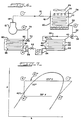
- an air cooling system in accordance with the present invention is shown generally at 10.
- the main components of such a system comprise a compressor 12 which may be a reciprocating, rotary, or centrifugal compressor.
- Compressor 12 has an outlet 14 which connects to tubing 16 providing for the outlet of a working fluid, usually a gaseous refrigerant, from compressor 12 to the inlet 18 of evaporative condenser 20.
- Evaporative condenser 20 can be a water cooled, air cooled or evaporatively cooled (as shown) condenser.
- Inlet 18 is connected to internal tubing 22 which forms a coil in evaporative condenser 20 exiting at 30. Cooling water 28 being recirculated from beneath the coil 22 exits through a sprayhead system 24 such that cooling water falls over coil 22.
- An appropriate fan mechanism 26 is usually also provided.
- Outlet 30 from evaporative condenser 20 connects to tubing 32 which enters a valve 34.
- Valve 34 has two outlets, 35 and 38.
- Outlet 36 extends to inlet 42 of thermal storage unit 40 and valve 70.
- Outlet 38 extends to valve 54 and section 60 which extends to valve 64.
- Valve 54 connects to outlet 44 of thermal storage unit 40, which is actually the outlet of coil tubing 46 extending from inlet 42 to outlet 44.
- Coil tubing 46 typically comprises metallic or plastic tubing wound in a serpentine manner throughout the tank 52 of thermal storage unit 40 such that the majority of the phase change material or water 50 can be frozen around the outside of tubing 46.
- Outlet 44 of thermal storage unit 40 also can enter an expansion device 56 which in turn has an outlet 58 connected to tubing section 60 and section 62.
- Outlet 62 is connected to valve 64 which in turn is connected to expansion device 66 which has an outlet 84 to inlet 84 of evaporator coil 80.
- Evaporator coil 80 includes internal tubing 86 which extends from inlet 84 to outlet 82.
- Outlet 82 of evaporator coil 80 extends via tubing to valve 70, which in turn has an outlet 74 extending to inlet 76 of compressor 12.
- Evaporator coil 80 also includes air movement means whereby air to be cooled is passed across coil 86 and thereby distributed throughout the building to which air cooling system 10 is connected.
- expansion devices 66 and 56 are thermostatic expansion valves which sense the pressure and temperature of the refrigerant gas leaving the evaporator 80 at 82 and leaving the thermal storage unit 40 at 42 and thereby control the flow of liquid refrigerant from line 32 into the evaporator 80 and into the thermal storage unit 40 to insure all the refrigerant is vaporized therein and to prevent damage to the compressor by liquid refrigerant.
- Sufficient refrigerant is intially charged into the system to ensure that liquid containing lines will be filled and into the evaporative condenser coil 22 in all modes of operation. Any variation in quantity of liquid refrigerant required from one condition to another is made up by maintaining an excess in the lower tubes of the evaporative condenser coil 22.
- expansion devices such as orifices and capillary tubes may be applied to control refrigerant flow.
- external receivers may be employed to ensure that liquid containing lines are full and to provide for refrigerant quantity variation from condition to condition when it is deemed undersirable to store excess in the evaporative condenser coil 22.
- Mode #1 provides conventional cooling to about 75% of the rated capacity of cooling system 10.
- outlet 14 of compressor 12 provides compressed working fluid, usually gaseous refrigerant, via line 16 to evaporative condenser 20.
- the cooled working fluid leaves outlet 30 of evaporator condenser 20 and passes through via line 32 through valve 34 and into line 38.
- From line 38 the pressurized and cooled working fluid passes through valve 64 and into expansion device 66.
- the expanded working fluid enters inlet 84 of evaporative coil 80 and passes through coil 86 thereby providing cooling to the air moving across coil 86.
- the warm and expanded working fluid leaves evaporative coil 80 at outlet 82 and enters lines 72 and 74 and inlet 76 of compressor 12.
- thermal storage unit 40 is bypassed in the Mode #1 operating condition for conventional cooling.
- Figure 3 is a P-h diagram, showing the thermodynamic properties of the working fluid (refrigerant), having P, or pressure, as its ordinate and h, or enthalpy, as its abscissa.
- the curved line envelopes the properties of the fluid under saturated conditions with superheated gas to the right of the saturation envelope and subcooled liquid to the left of the saturation envelope.
- Circled numbers in Figures 2 & 3 correspond to conditions Mode #1 described herein.
- condition 1 the warm, high-pressure gas being discharged from the compressor, can be seen in Figure 3 to be superheated.
- the gas passes into the coil 22 and is evaporatively cooled and caused to condense to a liquid at essentially a constant pressure, it can be seen on Figure 3 to emerge from the coil 22 at condition 2.
- the amount of heat that was liberated during the condensing process is proportional to the difference in h, or enthalpy, between conditions 1 and 2.
- condition 4 Upon reaching she compressor at condition 4, the working fluid gas is again compressed to condition 1, wherein the difference in the h values between conditions 1 and 4 is proportional to the amount of work expended by the compressor to achieve the compression.
- Compressor 12 provides at its outlet 14 compressed working fluid, usually a gaseous refrigerant, along line 16 to inlet 18 of evaporative condenser 20. Condensed and cooled working fluid exits evaporative condenser 20 at outlet 30 and is supplied along 32 through valve 34 to line 38 and line 60 to expansion device 56. The expanded cooled working fluid enters outlet 44 of thermal storage unit 40 and flows along coil 40 to inlet 42 of thermal storage unit 40.
- compressed working fluid usually a gaseous refrigerant
- the phase change material usually water 50
- the phase change material is frozen around the outside of coil 46.
- the working fluid leaves inlet 42 and passes through line 68 through valve 70 into line 74 and into inlet 76 of compressor 12.
- the air cooling system 10 is shut down for the remainder of the evening. Note that in Mode #2, the ice forming mode, evaporator coil 80 is not included in the routing of the working fluid through air cooling system to by appropriate positioning of the valves.
- Compressor 12 provides compressed working fluid at its outlet 14 which is supplied via lines 16 to inlet 18 of evaporative condenser 20. Condensed and cooled working fluid exits condenser 20 at outlet 30 and passes along line 32 to valve 34 and then along line 36 to inlet 42 of thermal storage unit 40. Working fluid passes along coil 46 through frozen water 50 thereby melting frozen water 50 which has built up upon coil 46 thereby further chilling working fluid as it passes through coil 46. Such further chilled working fluid exits thermal storage unit 40 at outlet 44 and passes through valve 54 and 64 into expansion device 66.
- the expanded and chilled working fluid enters evaporator coil 80 at inlet 84 and passes through coil 86 and exits evaporator coil at outlet 82.
- the warmed and expanded working fluid passes through valve 70 and line 74 back into inlet 76 of compressor 12.
- Air passing across coil 86 of evaporator coil 80 is provided with enhanced cooling due to the lower entry temperature of working fluid when it enters inlet 84 as opposed to the operation in Mode #1. This enhanced cooling provides approximately 25% additional capacity to air cooling system 10 thereby permitting air cooling system 10 to provide its rated cooling capacity.
- Mode #1 operation the compressed gaseous working fluid leaves the compressor at condition 1'', passes into the evaporative condenser and is condensed to a liquid and is further cooled to condition 2''. But in contrast to Mode #1 operation, the high pressure liquid now passes through the coil of the thermal storage unit causing it to be cooled even further to condition 3'' by the melting ice.
- the cold liquid passes through the expansion device 66 and flows to the evaporator at condition 4''.
- the working fluid is nearly all liquid with a much smaller component of gas. This is evident by the h value which is lower than in Mode #1. With more liquid fluid to boil, the fluid absorbs much more heat from the air passing over the evaporator coil as it transforms from condition 4'' to condition 5'', approximately 25% more.
- the air cooling system of the present invention can accordingly operate in three different modes.
- Mode #1 the air cooling system operates as an ordinary air conditioning system having a compressor 12, evaporative condenser 20, and evaporator coil 80.
- Such a system can be designed to provide the air conditioning needs of a building during the majority of the days during which air conditioning is needed.
- Lower electricity costs during the operating season are provided at essentially no increase in capital costs due to the smaller compressor and smaller evaporative condenser offsetting the added cost of the thermal storage unit.
- the evaporator coil is identical with that of the conventional system since it must be sized for the maximum building load in both cases.
- air cooling system 10 can be operated with compressor 12, evaporative condenser 20 and thermal storage unit 40 operating in series with evaporative coil 80 not included in the path of the operating system. Such operation provides extra chilled working fluid to the thermal storage unit 40 thereby freezing water around the coils 46 of thermal storage unit 40. When sufficient ice is formed around coils 46, the air cooling system is shut down for the rest of the night. In Mode #3, which is utilized only during those days and times when the full rated cooling capacity of air cooling system 10 is necessary, extra cooled air is provided by air cooling system 10. Such cooling is provided with the operation of compressor 12, evaporative condenser 20, thermal storage unit 40, and evaporative coil 80 operating in series.
- Working fluid entering thermal storage unit 40 is further chilled due to the ice surrounding coils 46 in thermal storage unit 40 thereby providing extra chilled fluid to evaporative coil 80. Accordingly, air passing across evaporative coil 80 is supplementally chilled to the full rated capacity of air cooling system 10 thereby providing the building the supplemental cooling needed to meet the cooling load of the hottest days of the year.
- Such additional cooling is provided without sizing of air conditioning system 10 with compressors and, evaporative condensers rated to meet such extreme demands, but rather, such components need only be sized to about 75% of such peak demands with the extra 25% of cooling provided by the thermal storage unit 40.
Landscapes
- Engineering & Computer Science (AREA)
- General Engineering & Computer Science (AREA)
- Combustion & Propulsion (AREA)
- Chemical & Material Sciences (AREA)
- Mechanical Engineering (AREA)
- Physics & Mathematics (AREA)
- Thermal Sciences (AREA)
- Life Sciences & Earth Sciences (AREA)
- Sustainable Development (AREA)
- Devices That Are Associated With Refrigeration Equipment (AREA)
- Other Air-Conditioning Systems (AREA)
- Compression-Type Refrigeration Machines With Reversible Cycles (AREA)
- Central Heating Systems (AREA)
- Sorption Type Refrigeration Machines (AREA)
Claims (17)
- Système de refroidissement comprenant
un moyen de compresseur (12) ayant une admission (76) et une sortie (14) pour un fluide de fonctionnement,
un moyen de condenseur (20) ayant une admission (18) et une sortie (30) pour un fluide de fonctionnement,
un moyen d'évaporateur (80) ayant une admission (84) et une sortie (82) pour un fluide de fonctionnement,
et un moyen d'accumulation thermique (40) ayant une admission (42) et une sortie (44) pour un fluide de fonctionnement,
la sortie (14) du moyen de compresseur étant branchée à l'admission (18) du moyen de condenseur et le système comprenant en outre des moyens pour sélectionner un de trois modes de fonctionnement, les modes comprenant:
un premier mode dans lequel la sortie (30) des moyens de condenseur est branchée à l'admission (84) des moyens d'évaporateur évitant les moyens d'accumulation thermique (40);
un deuxième mode dans lequel la sortie (30) du moyen de condenseur est branchée au moyen d'accumulation thermique, le moyen d'accumulation thermique étant branché à l'admission (76) du moyen de compresseur évitant le moyen d'évaporateur (80);
un troisième mode dans lequel la sortie (30) du moyen de condenseur est branchée à l'admission (42) du moyen d'accumulation thermique, la sortie (44) du moyen d'accumulation thermique étant branchée à l'admission (84) du moyen d'évaporateur;
et caractérisé en ce que dans le deuxième mode, la sortie (30) du moyen de condenseur est branchée à la sortie (44) du moyen d'accumulation thermique et l'admission (42) du moyen d'accumulation thermique est branchée à l'admission (76) du moyen de compresseur, de sorte que dans le deuxième mode le sens de circulation du fluide de fonctionnement à travers le moyen d'accumulation thermique (40) est opposé au sens de circulation dans le troisième mode. - Système de refroidissement suivant la revendication 1, dans lequel les moyens de sélection comprend des moyens de vanne (34, 54, 64, 70) qui peuvent fonctionner de telle sorte que dans le troisième mode de fonctionnement le moyen de condenseur (20), le moyen d'accumulation thermique (40), le moyen d'évaporateur (80) et le moyen de compresseur (12) sont branchés en série ou de telle sorte que dans le deuxième mode de fonctionnement le moyen de condenseur (20), le moyen d'accumulation thermique (40) et le moyen de compresseur (12) sont branchés en série ou de telle sorte que dans le premier mode de fonctionnement le moyen de condenseur (20), le moyen d'évaporateur (80) et le moyen de compresseur (12) sont branchés en série, comme on le désire.
- Système de refroidissement suivant l'une quelconque des revendications précédentes, dans lequel le moyen d'accumulation thermique (40) comprend une tuyauterie (46) à l'intérieur d'un réservoir (52) contenant un liquide (50), la tuyauterie suivant un chemin tel à travers le réservoir qu'une partie importante de sa longueur se trouve sous le liquide.
- Système de refroidissement suivant la revendication 3, dans lequel la tuyauterie (46) suit un chemin tel à travers le réservoir (52) que la plus grande partie du liquide (50) peut être gelée autour de la tuyauterie.
- Système de refroidissement suivant la revendication 3 ou 4, dans lequel la tuyauterie du moyen d'accumulation (46) est une bobine formant un chemin en serpentin à l'intérieur dudit réservoir (52).
- Système de refroidissement suivant l'une quelconque des revendications 1 à 5, dans lequel le fluide de fonctionnement est un liquide réfrigérant.
- Système de refroidissement suivant l'une quelconque des revendications 1 à 6, dans lequel le liquide dans le réservoir du moyen d'accumulation thermique (52) est de l'eau.
- Système de refroidissement suivant l'une quelconque des revendications précédentes, comprenant en outre un dispositif d'expansion (66) à l'admission du moyen d'évaporateur.
- Système de refroidissement suivant l'une quelconque des revendications précédentes, comprenant un dispositif d'expansion à la sortie du moyen d'accumulation thermique (56).
- Système de refroidissement suivant l'une quelconque des revendications précédentes dans lequel le moyen de condenseur (20) comprend une bobine de condenseur (22) à travers laquelle passe un fluide de fonctionnement et le moyen d'évaporateur (80) comprend une bobine d'évaporateur (86) à travers laquelle passe le fluide de fonctionnement.
- Système de refroidissement suivant l'une quelconque des revendications précédentes, comprenant un moyen de récepteur pour garantir que les conduites contenant le liquide sont remplies.
- Procédé pour fournir un refroidissement supplémentaire pour un système de conditionnement d'air comprenant les étapes:
d'accumulation d'une capacité thermique, pendant les périodes sans demande de refroidissement, en faisant circuler un fluide de fonctionnement sortant d'un moyen de condenseur (20) à travers un moyen d'accumulation thermique (40) avant de faire entrer le fluide de fonctionnement dans un moyen de compresseur (12) en évitant un moyen d'évaporateur(80); et
de refroidissement supplémentaire du fluide de fonctionnement, pendant les périodes de forte demande de refroidissement, en faisant circuler le fluide de fonctionnement sortant du moyen de condenseur (20) à travers le moyen d'accumulation thermique (40) pour refroidir de manière supplémentaire le fluide de fonctionnement, avant de faire entrer le fluide de fonctionnement dans le moyen de compresseur (12) via le moyen d'évaporateur (80); et caractérisé en ce que:
dans l'étape de refroidissement supplémentaire du fluide de fonctionnement, le fluide de fonctionnement circule à travers le moyen d'accumulation thermique dans une direction opposée à la direction de circulation à travers le moyen d'accumulation thermique pendant l'étape d'accumulation de capacité de refroidissement. - Procédé de refroidissement d'air suivant la revendication 12 dans lequel pendant l'étape d'accumulation de la capacité thermique, lorsque le fluide de fonctionnement circule à travers le moyen d'accumulation thermique (40) en évitant le moyen d'évaporateur, le liquide (50) dans le moyen d'accumulation thermique est gelé autour de l'extérieur d'une tuyauterie (46) à travers laquelle le fluide de fonctionnement circule.
- Procédé de refroidissement d'air suivant l'une quelconque des revendications 12 ou 13, dans lequel pendant l'étape de refroidissement supplémentaire du fluide de fonctionnement, lorsque le fluide de fonctionnement traverse le moyen d'accumulation thermique (40) et le moyen d'évaporateur (80), l'air passant à travers le moyen d'évaporateur est soumis à un niveau de refroidissement plus élevé que le fluide de fonctionnement passant à travers le moyen d'accumulation thermique (40) est réfrigéré lorsqu'il traverse la tuyauterie (46) sur l'extérieur de laquelle du liquide gelé s'est formé.
- Procédé de refroidissement d'air suivant l'une quelconque des revendications 12 ou 14, dans lequel le moyen d'accumulation thermique (40) comprend un réservoir (52) contenant un liquide (50) et le liquide comprend de l'eau.
- Procédé de refroidissement d'air suivant l'une quelconque des revendications 12 ou 14, dans lequel le moyen d'accumulation thermique (40) comprend un réservoir (52) contenant un liquide (50) et le liquide comprend un matériau à changement de phase tel qu'un sel eutectique.
- Procédé de refroidissement d'air suivant l'une quelconque des revendications 12 ou 16, comprenant en outre l'étape de passage du fluide de fonctionnement à travers le moyen de récepteur pour garantir que les conduites contenant le liquide sont remplies.
Priority Applications (1)
| Application Number | Priority Date | Filing Date | Title |
|---|---|---|---|
| AT90306184T ATE96217T1 (de) | 1989-06-07 | 1990-06-07 | Kuehlanlage mit zusatzwaermespeicher. |
Applications Claiming Priority (2)
| Application Number | Priority Date | Filing Date | Title |
|---|---|---|---|
| US36296689A | 1989-06-07 | 1989-06-07 | |
| US362966 | 1989-06-07 |
Publications (3)
| Publication Number | Publication Date |
|---|---|
| EP0402131A2 EP0402131A2 (fr) | 1990-12-12 |
| EP0402131A3 EP0402131A3 (fr) | 1991-04-17 |
| EP0402131B1 true EP0402131B1 (fr) | 1993-10-20 |
Family
ID=23428243
Family Applications (1)
| Application Number | Title | Priority Date | Filing Date |
|---|---|---|---|
| EP90306184A Expired - Lifetime EP0402131B1 (fr) | 1989-06-07 | 1990-06-07 | Installation frigorifique avec accumulateur thermique supplémentaire |
Country Status (8)
| Country | Link |
|---|---|
| EP (1) | EP0402131B1 (fr) |
| JP (1) | JPH0320570A (fr) |
| AT (1) | ATE96217T1 (fr) |
| AU (1) | AU626040B2 (fr) |
| BR (1) | BR9002668A (fr) |
| CA (1) | CA2016690C (fr) |
| DE (1) | DE69004009T2 (fr) |
| ES (1) | ES2047854T3 (fr) |
Cited By (6)
| Publication number | Priority date | Publication date | Assignee | Title |
|---|---|---|---|---|
| US9476648B2 (en) | 2014-01-21 | 2016-10-25 | Drexel University | Systems and methods of using phase change material in power plants |
| WO2019165254A1 (fr) * | 2018-02-23 | 2019-08-29 | Emerson Climate Technologies, Inc. | Système de régulation et de climatisation à dispositif de stockage thermique |
| US10598395B2 (en) | 2018-05-15 | 2020-03-24 | Emerson Climate Technologies, Inc. | Climate-control system with ground loop |
| US10890383B2 (en) | 2014-01-21 | 2021-01-12 | Drexel University | Systems and methods of using phase change material in power plants |
| US11346583B2 (en) | 2018-06-27 | 2022-05-31 | Emerson Climate Technologies, Inc. | Climate-control system having vapor-injection compressors |
| US11585608B2 (en) | 2018-02-05 | 2023-02-21 | Emerson Climate Technologies, Inc. | Climate-control system having thermal storage tank |
Families Citing this family (10)
| Publication number | Priority date | Publication date | Assignee | Title |
|---|---|---|---|---|
| TW247932B (fr) * | 1992-10-22 | 1995-05-21 | Berhaz Pty Ltd | |
| US5386709A (en) * | 1992-12-10 | 1995-02-07 | Baltimore Aircoil Company, Inc. | Subcooling and proportional control of subcooling of liquid refrigerant circuits with thermal storage or low temperature reservoirs |
| DE4243279A1 (de) | 1992-12-21 | 1994-06-23 | Bayer Ag | Substituierte Triole |
| AU751294C (en) * | 2001-07-13 | 2005-04-07 | Baltimore Aircoil Company Inc. | System and method of cooling |
| AU2003903551A0 (en) * | 2003-07-09 | 2003-07-24 | Muller Industries Australia Pty Ltd | System and method of cooling |
| ES2663353T3 (es) * | 2011-02-25 | 2018-04-12 | Carrier Corporation | Sistema acondicionador de aire con almacenamiento de hielo |
| CN107036344B (zh) | 2016-02-03 | 2021-06-15 | 开利公司 | 制冷系统、复叠式制冷系统及其控制方法 |
| DE102016214119A1 (de) | 2016-08-01 | 2018-02-01 | Volkswagen Aktiengesellschaft | Klimatisierungsvorrichtung für ein Kraftfahrzeug und Verfahren zu deren Betrieb |
| CN108050629B (zh) * | 2018-01-20 | 2023-07-11 | 中煤能源研究院有限责任公司 | 基于间接蒸发冷却冷水机的双冷源井下制冷系统及方法 |
| CN113324298B (zh) * | 2021-06-23 | 2021-11-26 | 广州科力新能源股份有限公司 | 一种冰蓄冷的控制装置和冰蓄冷系统 |
Citations (2)
| Publication number | Priority date | Publication date | Assignee | Title |
|---|---|---|---|---|
| US4637219A (en) * | 1986-04-23 | 1987-01-20 | Enron Corp. | Peak shaving system for air conditioning |
| JPS63116055A (ja) * | 1986-10-31 | 1988-05-20 | 日本鋼管株式会社 | 蓄冷式冷凍装置 |
Family Cites Families (2)
| Publication number | Priority date | Publication date | Assignee | Title |
|---|---|---|---|---|
| US4720984A (en) * | 1986-05-23 | 1988-01-26 | Transphase Systems, Inc. | Apparatus for storing cooling capacity |
| DE3704182A1 (de) * | 1987-02-11 | 1988-08-25 | Forschungszentrum Fuer Kaeltet | Kuehlanlage |
-
1990
- 1990-05-14 CA CA002016690A patent/CA2016690C/fr not_active Expired - Fee Related
- 1990-06-05 BR BR909002668A patent/BR9002668A/pt not_active IP Right Cessation
- 1990-06-06 AU AU56850/90A patent/AU626040B2/en not_active Ceased
- 1990-06-06 JP JP2146406A patent/JPH0320570A/ja active Pending
- 1990-06-07 AT AT90306184T patent/ATE96217T1/de not_active IP Right Cessation
- 1990-06-07 EP EP90306184A patent/EP0402131B1/fr not_active Expired - Lifetime
- 1990-06-07 DE DE90306184T patent/DE69004009T2/de not_active Expired - Fee Related
- 1990-06-07 ES ES90306184T patent/ES2047854T3/es not_active Expired - Lifetime
Patent Citations (2)
| Publication number | Priority date | Publication date | Assignee | Title |
|---|---|---|---|---|
| US4637219A (en) * | 1986-04-23 | 1987-01-20 | Enron Corp. | Peak shaving system for air conditioning |
| JPS63116055A (ja) * | 1986-10-31 | 1988-05-20 | 日本鋼管株式会社 | 蓄冷式冷凍装置 |
Cited By (7)
| Publication number | Priority date | Publication date | Assignee | Title |
|---|---|---|---|---|
| US9476648B2 (en) | 2014-01-21 | 2016-10-25 | Drexel University | Systems and methods of using phase change material in power plants |
| US10890383B2 (en) | 2014-01-21 | 2021-01-12 | Drexel University | Systems and methods of using phase change material in power plants |
| US11585608B2 (en) | 2018-02-05 | 2023-02-21 | Emerson Climate Technologies, Inc. | Climate-control system having thermal storage tank |
| WO2019165254A1 (fr) * | 2018-02-23 | 2019-08-29 | Emerson Climate Technologies, Inc. | Système de régulation et de climatisation à dispositif de stockage thermique |
| US11149971B2 (en) | 2018-02-23 | 2021-10-19 | Emerson Climate Technologies, Inc. | Climate-control system with thermal storage device |
| US10598395B2 (en) | 2018-05-15 | 2020-03-24 | Emerson Climate Technologies, Inc. | Climate-control system with ground loop |
| US11346583B2 (en) | 2018-06-27 | 2022-05-31 | Emerson Climate Technologies, Inc. | Climate-control system having vapor-injection compressors |
Also Published As
| Publication number | Publication date |
|---|---|
| ATE96217T1 (de) | 1993-11-15 |
| AU626040B2 (en) | 1992-07-23 |
| DE69004009D1 (de) | 1993-11-25 |
| AU5685090A (en) | 1990-12-13 |
| EP0402131A3 (fr) | 1991-04-17 |
| EP0402131A2 (fr) | 1990-12-12 |
| CA2016690A1 (fr) | 1990-12-07 |
| CA2016690C (fr) | 1994-03-08 |
| JPH0320570A (ja) | 1991-01-29 |
| ES2047854T3 (es) | 1994-03-01 |
| BR9002668A (pt) | 1991-08-20 |
| DE69004009T2 (de) | 1994-02-17 |
Similar Documents
| Publication | Publication Date | Title |
|---|---|---|
| US4964279A (en) | Cooling system with supplemental thermal storage | |
| EP0402131B1 (fr) | Installation frigorifique avec accumulateur thermique supplémentaire | |
| KR100227878B1 (ko) | 복합 다중모드 공기 조화장치 및 네가티브 에너지 저장시스템 | |
| EP1682832B1 (fr) | Appareil de refrigeration | |
| JP2894421B2 (ja) | 蓄熱式空気調和装置及び除霜方法 | |
| US5307642A (en) | Refrigerant management control and method for a thermal energy storage system | |
| US5682752A (en) | Refrigerant management control and method for a thermal energy storage system | |
| US7124594B2 (en) | High efficiency refrigerant based energy storage and cooling system | |
| US8707723B2 (en) | Multiple refrigerant thermal energy storage and cooling system with secondary refrigerant isolation | |
| EP0601875B1 (fr) | Dispositif pour sous-refroidir le condensat des circuits frigorifiques | |
| EP0602911B1 (fr) | Système de refroidissement | |
| US7854129B2 (en) | Refrigeration apparatus | |
| US4608836A (en) | Multi-mode off-peak storage heat pump | |
| CN100559100C (zh) | 蓄冷式空调装置 | |
| US20110048058A1 (en) | Thermal energy storage and cooling system with enhanced heat exchange capability | |
| US20020033024A1 (en) | Utilization of harvest and/or melt water from an ice machine for a refrigerant subcool/precool system and method therefor | |
| US20130074531A1 (en) | Refrigerant circuit with integrated multi-mode thermal energy storage | |
| US5673567A (en) | Refrigeration system with heat reclaim and method of operation | |
| EP0760453A2 (fr) | Système de conditionnement d'air avec sous-refroidisseur et dispositifs détendeurs en série | |
| US3390540A (en) | Multiple evaporator refrigeration systems | |
| JPH10223442A (ja) | 変電機器冷却システム及びその運転方法 | |
| CA2223405A1 (fr) | Appareil et configurations de circuits pour systemes de refrigeration | |
| EP1811236A2 (fr) | Appareil de réfrigération avec contrôleur de fonction réfrigérante | |
| JP2757660B2 (ja) | 蓄熱式空気調和装置 | |
| JP3370501B2 (ja) | 冷房システム |
Legal Events
| Date | Code | Title | Description |
|---|---|---|---|
| PUAI | Public reference made under article 153(3) epc to a published international application that has entered the european phase |
Free format text: ORIGINAL CODE: 0009012 |
|
| AK | Designated contracting states |
Kind code of ref document: A2 Designated state(s): AT BE CH DE DK ES FR GB GR IT LI LU NL SE |
|
| PUAL | Search report despatched |
Free format text: ORIGINAL CODE: 0009013 |
|
| AK | Designated contracting states |
Kind code of ref document: A3 Designated state(s): AT BE CH DE DK ES FR GB GR IT LI LU NL SE |
|
| 17P | Request for examination filed |
Effective date: 19910816 |
|
| 17Q | First examination report despatched |
Effective date: 19920131 |
|
| ITF | It: translation for a ep patent filed | ||
| GRAA | (expected) grant |
Free format text: ORIGINAL CODE: 0009210 |
|
| AK | Designated contracting states |
Kind code of ref document: B1 Designated state(s): AT BE CH DE DK ES FR GB GR IT LI LU NL SE |
|
| PG25 | Lapsed in a contracting state [announced via postgrant information from national office to epo] |
Ref country code: GR Free format text: LAPSE BECAUSE OF FAILURE TO SUBMIT A TRANSLATION OF THE DESCRIPTION OR TO PAY THE FEE WITHIN THE PRESCRIBED TIME-LIMIT Effective date: 19931020 Ref country code: DK Effective date: 19931020 Ref country code: AT Effective date: 19931020 |
|
| REF | Corresponds to: |
Ref document number: 96217 Country of ref document: AT Date of ref document: 19931115 Kind code of ref document: T |
|
| REF | Corresponds to: |
Ref document number: 69004009 Country of ref document: DE Date of ref document: 19931125 |
|
| ET | Fr: translation filed | ||
| REG | Reference to a national code |
Ref country code: ES Ref legal event code: FG2A Ref document number: 2047854 Country of ref document: ES Kind code of ref document: T3 |
|
| PGFP | Annual fee paid to national office [announced via postgrant information from national office to epo] |
Ref country code: DE Payment date: 19940527 Year of fee payment: 5 |
|
| PGFP | Annual fee paid to national office [announced via postgrant information from national office to epo] |
Ref country code: BE Payment date: 19940601 Year of fee payment: 5 |
|
| PGFP | Annual fee paid to national office [announced via postgrant information from national office to epo] |
Ref country code: GB Payment date: 19940603 Year of fee payment: 5 |
|
| PG25 | Lapsed in a contracting state [announced via postgrant information from national office to epo] |
Ref country code: SE Effective date: 19940608 |
|
| PGFP | Annual fee paid to national office [announced via postgrant information from national office to epo] |
Ref country code: FR Payment date: 19940616 Year of fee payment: 5 Ref country code: ES Payment date: 19940616 Year of fee payment: 5 |
|
| PG25 | Lapsed in a contracting state [announced via postgrant information from national office to epo] |
Ref country code: LU Free format text: LAPSE BECAUSE OF NON-PAYMENT OF DUE FEES Effective date: 19940630 Ref country code: LI Effective date: 19940630 Ref country code: CH Effective date: 19940630 |
|
| PLBE | No opposition filed within time limit |
Free format text: ORIGINAL CODE: 0009261 |
|
| STAA | Information on the status of an ep patent application or granted ep patent |
Free format text: STATUS: NO OPPOSITION FILED WITHIN TIME LIMIT |
|
| 26N | No opposition filed | ||
| PG25 | Lapsed in a contracting state [announced via postgrant information from national office to epo] |
Ref country code: NL Effective date: 19950101 |
|
| EUG | Se: european patent has lapsed |
Ref document number: 90306184.4 Effective date: 19950110 |
|
| NLV4 | Nl: lapsed or anulled due to non-payment of the annual fee | ||
| REG | Reference to a national code |
Ref country code: CH Ref legal event code: PL |
|
| EUG | Se: european patent has lapsed |
Ref document number: 90306184.4 |
|
| PG25 | Lapsed in a contracting state [announced via postgrant information from national office to epo] |
Ref country code: GB Effective date: 19950607 |
|
| PG25 | Lapsed in a contracting state [announced via postgrant information from national office to epo] |
Ref country code: ES Free format text: LAPSE BECAUSE OF THE APPLICANT RENOUNCES Effective date: 19950608 |
|
| ITTA | It: last paid annual fee | ||
| PG25 | Lapsed in a contracting state [announced via postgrant information from national office to epo] |
Ref country code: BE Effective date: 19950630 |
|
| BERE | Be: lapsed |
Owner name: BALTIMORE AIRCOIL CY INC. Effective date: 19950630 |
|
| GBPC | Gb: european patent ceased through non-payment of renewal fee |
Effective date: 19950607 |
|
| PG25 | Lapsed in a contracting state [announced via postgrant information from national office to epo] |
Ref country code: FR Effective date: 19960229 |
|
| PG25 | Lapsed in a contracting state [announced via postgrant information from national office to epo] |
Ref country code: DE Effective date: 19960301 |
|
| REG | Reference to a national code |
Ref country code: FR Ref legal event code: ST |
|
| REG | Reference to a national code |
Ref country code: ES Ref legal event code: FD2A Effective date: 19991007 |
|
| PG25 | Lapsed in a contracting state [announced via postgrant information from national office to epo] |
Ref country code: IT Free format text: LAPSE BECAUSE OF NON-PAYMENT OF DUE FEES;WARNING: LAPSES OF ITALIAN PATENTS WITH EFFECTIVE DATE BEFORE 2007 MAY HAVE OCCURRED AT ANY TIME BEFORE 2007. THE CORRECT EFFECTIVE DATE MAY BE DIFFERENT FROM THE ONE RECORDED. Effective date: 20050607 |