EP0402571A1 - Ventrikulostomie-Reservoir - Google Patents
Ventrikulostomie-Reservoir Download PDFInfo
- Publication number
- EP0402571A1 EP0402571A1 EP90104199A EP90104199A EP0402571A1 EP 0402571 A1 EP0402571 A1 EP 0402571A1 EP 90104199 A EP90104199 A EP 90104199A EP 90104199 A EP90104199 A EP 90104199A EP 0402571 A1 EP0402571 A1 EP 0402571A1
- Authority
- EP
- European Patent Office
- Prior art keywords
- base
- cap
- reservoir
- dome
- flange
- Prior art date
- Legal status (The legal status is an assumption and is not a legal conclusion. Google has not performed a legal analysis and makes no representation as to the accuracy of the status listed.)
- Granted
Links
- 230000002093 peripheral effect Effects 0.000 claims description 32
- 239000000853 adhesive Substances 0.000 claims description 14
- 230000001070 adhesive effect Effects 0.000 claims description 14
- 238000007789 sealing Methods 0.000 claims description 6
- 239000012530 fluid Substances 0.000 description 9
- 210000003625 skull Anatomy 0.000 description 9
- 210000004556 brain Anatomy 0.000 description 8
- 210000001175 cerebrospinal fluid Anatomy 0.000 description 8
- 238000001356 surgical procedure Methods 0.000 description 5
- 210000002837 heart atrium Anatomy 0.000 description 3
- 208000003906 hydrocephalus Diseases 0.000 description 3
- 238000002513 implantation Methods 0.000 description 3
- 239000000463 material Substances 0.000 description 3
- 238000005070 sampling Methods 0.000 description 3
- 210000001124 body fluid Anatomy 0.000 description 2
- 239000010839 body fluid Substances 0.000 description 2
- 238000002347 injection Methods 0.000 description 2
- 239000007924 injection Substances 0.000 description 2
- 238000004519 manufacturing process Methods 0.000 description 2
- 239000002991 molded plastic Substances 0.000 description 2
- 239000004743 Polypropylene Substances 0.000 description 1
- 238000009825 accumulation Methods 0.000 description 1
- 239000008280 blood Substances 0.000 description 1
- 210000004369 blood Anatomy 0.000 description 1
- 230000015556 catabolic process Effects 0.000 description 1
- 238000004891 communication Methods 0.000 description 1
- 238000006731 degradation reaction Methods 0.000 description 1
- 238000005553 drilling Methods 0.000 description 1
- 239000013536 elastomeric material Substances 0.000 description 1
- 210000004731 jugular vein Anatomy 0.000 description 1
- 239000002184 metal Substances 0.000 description 1
- 238000012986 modification Methods 0.000 description 1
- 230000004048 modification Effects 0.000 description 1
- 238000012544 monitoring process Methods 0.000 description 1
- -1 polypropylene Polymers 0.000 description 1
- 229920001155 polypropylene Polymers 0.000 description 1
- 229920002379 silicone rubber Polymers 0.000 description 1
- 230000002792 vascular Effects 0.000 description 1
Images

Classifications
-
- A—HUMAN NECESSITIES
- A61—MEDICAL OR VETERINARY SCIENCE; HYGIENE
- A61M—DEVICES FOR INTRODUCING MEDIA INTO, OR ONTO, THE BODY; DEVICES FOR TRANSDUCING BODY MEDIA OR FOR TAKING MEDIA FROM THE BODY; DEVICES FOR PRODUCING OR ENDING SLEEP OR STUPOR
- A61M27/00—Drainage appliance for wounds or the like, i.e. wound drains, implanted drains
- A61M27/002—Implant devices for drainage of body fluids from one part of the body to another
- A61M27/006—Cerebrospinal drainage; Accessories therefor, e.g. valves
Definitions
- This invention relates generally to surgically implantable valves. More particularly, this invention relates to devices for the drainage of cerebrospinal fluid from the ventricle of the brain and for monitoring such drainage.
- cerebrospinal fluid accumulated in the brain ventricles is drained away by a catheter inserted into the ventricle through the skull.
- the catheter is connected to a conduit which conducts the fluid away from the brain to be reintroduced into the vascular system, as by extending through the patient's jugular vein to the atrium portion of the heart.
- a pump or valve is placed in the conduit between the brain and the heart atrium. Examples of such pump and valve devices are shown in U.S. Patent No. 4,560,375, to Schulte et al.
- Ventriculostomy reservoirs are often utilized in connection with such pumps or valves to provide a convenient location for sampling accumulated cerebrospinal fluid as close to the brain ventricles as possible.
- Such ventriculostomy reservoirs may be placed over a burr hole through the skull to facilitate sampling of cerebrospinal fluid before the implantation of the fluid conduit.
- Prior ventriculostomy reservoirs typically include a metal base having a catheter connector, an integral, upwardly extending cylindrical wall portion, and a flange portion integrally formed with and overlying the wall portion.
- a cap made of a silicone elastomer material is typically provided to enclose the upper end of the base and define, with the base, an internal reservoir.
- the cap usually includes an annular internal recess configured to fit over the flange portion of the base.
- the cap and the base of such prior ventriculostomy reservoirs are usually separated prior to implantation.
- the surgeon after drilling a burr hole through the skull, attaches a catheter to the connector at the lower end of the base, and then positions the base on the skull.
- the surgeon has then been required to grasp the cap and stretch its peripheral edges over the upper flange of the base to position the flange within the recess of the cap. This has, however, presented difficulties for the surgeon which the present invention eliminates.
- the present invention resides in a ventriculostomy reservoir having improved assembly characteristics, and which fulfills each of the needs set forth above.
- the improved ventriculostomy reservoir comprises, generally, a base configured to provide an internal reservoir well, and a cap which is positioned over the base to enclose the reservoir well.
- the base includes an inlet and an upwardly extending wall portion integrally formed with the inlet, and the cap includes a dome portion and an outlet for the reservoir.
- Means are provided for attaching the cap to the base to form a fluid-tight fit therebetween.
- the attaching means includes a first means associated with the base for connecting the base to the cap, and a second means associated with the cap for connecting the base to the cap.
- the first and second connecting means cooperate with one another to form an interference fit which prevents fluid leakage.
- the first and second connecting means may include a detent provided in one of the first and second connecting means, and a protrusion provided on the other of the first and second connecting means, wherein the detent and the protrusion snap-fit together to securely hold the cap to the base.
- the base is formed of a rigid material such as polypropylene, and is configured to provide an internal reservoir well.
- This base includes a catheter connector defining a reservoir inlet, and the wall portion is integrally formed with the catheter connector and extends upwardly therefrom.
- the cap is preferably constructed of an elastomeric material and is placed over the base to enclose the reservoir well and define, with the base, an internal reservoir.
- the cap includes a peripheral supporting portion formed integrally with the dome portion, and an outlet arm which defines an outlet channel.
- the outlet arm is integrally formed with the dome. Reinforced sheeting is attached to the dome peripheral supporting portion in order to minimize elastic stretching of a lower surface of the dome.
- a rigid cap insert is securely affixed to the cap and is positioned for engagement with the base.
- the cap insert includes an annular flange-like portion which is attached to the dome peripheral supporting portion.
- the annular flange-like portion of the cap insert includes a plurality of apertures filled with an adhesive which tends to secure the cap insert to the dome peripheral supporting portion.
- the base includes a flange portion integrally formed with and overlying the wall portion, which flange portion includes an upper planar surface.
- the dome includes a lower sealing surface which lies against the upper planar surface of the flange portion of the base.
- the cap insert includes a cylindrical portion which extends downwardly from the annular flange-like portion, and this downwardly extending cylindrical portion fits within the upwardly extending wall portion of the base.
- the first connecting means includes an encircling detent on an interior surface of the wall portion of the base, which is adjacent to the cylindrical portion of the cap insert.
- the second connecting means includes an encircling protrusion on an exterior surface of the cylindrical portion of the cap insert. Engagement between the protrusion and the detent connects the cap to the base and forms a fluid-tight seal therebetween.
- the annular flange-like portion of the cap insert is captured within the dome peripheral supporting portion to exteriorly surround an upper end of the base.
- the first connecting means includes an encircling detent on an exterior surface of the wall portion of the base which is adjacent to and surrounded by the cap insert.
- the second connecting means includes an encircling protrusion which extends inwardly from the annular flange-like portion of the cap insert. Again, the engagement between the protrusion and the detent connects the cap to the base and forms a fluid-tight seal therebetween.
- the annular flange-like portion of the cap insert is attached to the dome peripheral supporting portion to exteriorly surround an upper end of the base.
- the base includes a flange portion integrally formed with and overlying the wall portion, and the cap insert is configured to exteriorly surround the base flange.
- the cap insert is provided a detent which receives the outer periphery of the base flange, and the cap insert further overlies the base flange and includes means extending into the reservoir well for engaging an interior surface of the wall portion of the base in an interference fit.
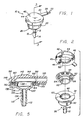
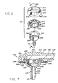
- the present invention is concerned with an improved ventriculostomy reservoir, generally designated in FIGS. 1 through 4 by the reference number 10, in FIG. 5 by the reference number 110, and in FIGS. 6 and 7 by the reference number 210.
- These improved ventriculostomy reservoirs 10, 110 and 210 are intended for use in a surgically implanted shunt system for draining fluid from one portion of the human body to another.
- the reservoir 10 in such a system, the reservoir includes an inlet connector 12 which receives one end of a piece of surgical tubing or a catheter 14.
- the inlet tube or catheter 14 slides over the inlet connector 12, and is secured in place by a single ligature 16.
- the ligature 16 is preferably secured around the catheter 14 just inside of an annular ridge 18 formed near the end of the inlet connector 12.
- the reservoirs 10, 110 and 210 also include an outlet connector or arm 20 which is dimensioned to receive a straight connector 22 or plug, having an end resembling the inlet connector 12.
- the outlet connector or arm 20 slides over the straight connector 22, and is secured in place by a single ligature 24 in the same manner that the catheter 14 is secured to the inlet connector 12.
- the inlet connector 12 and the catheter 14 are inserted through the skull into a brain ventricle containing cerebrospinal fluid under pressure.
- the outlet connector 20 connects to a distal catheter (not shown) which serves to discharge cerebrospinal fluid into, for example, the atrium portion of a patient's heart.
- a suitable flow control valve for example either of those illustrated in U.S. Patent No. 4,560,375, the contents of which are incorporated herein by reference, may be interposed in fluid communication between the reservoir and the distal catheter.
- the reservoir will be surgically implanted on the patient's skull with a flap of skin overlying the reservoir.
- the reservoir 10 includes a relatively rigid, unitized molded plastic base 26 which is formed integrally with the inlet connector 12.
- the base 26 is configured to provide an internal reservoir well 28, and includes a wall portion 30 which extends upwardly from the inlet connector 12, and a flange portion 32 which is integrally formed with an overlies the wall portion.
- the wall portion 30 of the base 26 includes a lower frusto-conical section 34 which is formed with a stem 36 of the inlet connector 12, and an intermediate cylindrical section 38 which extends between the flange portion 32 and the frusto-conical section 34.
- the flange portion 32 includes an upper planar surface 40.
- An elastomeric cap 42 is positioned over the base 26 to enclose the reservoir well 28 and define, with the base, an internal reservoir.
- the cap 42 includes a dome portion 44 which is integrally formed with a peripheral supporting portion 46, and the outlet connector or arm 20.
- the dome portion 44 is designed to permit injection into the reservoir well 28 by a hypodermic needle.
- the base When the cap 42 is placed over the base 26, the base functions as a needle shield to prevent a physician from inadvertently inserting the needle too far, which could puncture the base and extend beyond the limits of the reservoir well 28.
- the cap In order to strengthen the cap 42 and facilitate the forming of a fluid-tight seal between the cap and the base 26, the cap is formed with a planar undersurface 48 which faces the flange planar surface 40. Reinforced sheeting 49 is adhesively fixed to the cap planar undersurface 48, and abuts against the flange planar surface 40 to form a seal therebetween. Moreover, a rigid cap insert 50 is positioned within an annular channel 52 provided within the peripheral supporting portion 46 of the cap 42, which cap insert snap-fits into the base 26 to securely hold the cap to the base and also form a fluid-tight seal therebetween.
- the rigid cap insert 50 includes an annular flange-like portion 54 which is captured within the annular channel 52 of the cap 42.
- the annular flange-like portion 54 of the cap insert 50 includes a series of apertures 56 which are filled with an adhesive 58.
- the adhesive 58 tends to secure the annular flange-like portion 54 within the peripheral supporting portion 46 of the cap 42.
- the cap insert 50 further includes a cylindrical portion 60 which extends downwardly from the flange-portion 54 and fits within the upwardly extending wall portion 30 of the base 26.
- the wall portion 30, and more specifically the cylindrical section 38 of the base includes an encircling groove or recess 62 on an interior surface thereof, which is adjacent to the cylindrical portion 60 of the cap insert 50 when inserted within the wall portion 30.
- the cylindrical portion 60 includes an encircling protrusion 64 which is positioned and dimensioned to engage the grove 62 to connect the cap 42 to the base 26.
- This protrusion and recess arrangement for connecting the cap 42 to the base 26 enables a physician to quickly and easily assemble the ventriculostomy reservoir 10 during a surgical procedure.
- a catheter 14 is often connected to the inlet connector 12, and then the base 26 is positioned directly over a burr hole through the patient's skull.
- the physician only needs to insert the cylindrical portion 60 of the cap insert 50 (which is preassembled with the cap 42), to place the protrusion 64 within the recess 62.
- This arrangement forms a fluid-tight seal, and eliminates the requirement that the surgeon attempt to manipulate the cap and stretch it over the flange portion 32 of the base 26.
- contact between the flange planar surface 40 and the reinforced sheeting 49 attached to the cap planar undersurface 48 tends to create a secondary seal which provides a backup against fluid leakage between the cap 42 and the base 26.
- FIG. 5 shows a rigid base 126 is formed integrally with the inlet connector 112.
- the base 126 is configured to provide an internal reservoir well 128 and includes an upwardly extending wall portion 130 integrally formed with the inlet connector.
- the wall portion 130 includes a lower frusto-conical section 134 which is formed with a stem 136 of the inlet connector 112.
- a cylindrical section 138 extends upwardly from the frusto-conical section 134.
- the embodiment of FIG. 5 does not include a flange portion such as that identified by the reference number 32 in connection with the first illustrated embodiment.
- An elastomeric cap 142 is positioned over the base 126 to enclose the reservoir well 128.
- the cap 142 includes a dome portion 144 which is integrally formed with a peripheral supporting portion 146, and the outlet connector or arm 120. Further, reinforced sheeting 149 is attached to the undersurface of the peripheral supporting portion 146.
- a rigid cap insert 150 is securely positioned within an annular channel 152 provided within the peripheral supporting portion 146 of the cap 142.
- the cap insert 150 includes an annular flange-like portion 154 which is positioned within the annular channel 152.
- This annular flange-like portion 154 is nearly identical to that described above in connection with the first embodiment, and includes a plurality of apertures 156 which are filled with an adhesive 158. The purpose of this adhesive 158 is to secure the cap insert 150 within the dome peripheral supporting portion 146.
- the ventriculostomy reservoir 110 illustrated in FIG. 5 differs from the embodiment illustrated in FIGS. 1 through 4 primarily in that the annular flange-like portion 154 is positioned within the dome peripheral supporting portion 146 to exteriorly surround an upper end of the base 126.
- an encircling recess 162 is provided on the exterior surface of the wall portion 130 of the base 126 adjacent to the cap insert 150 when the cap 142 is placed over the base 126.
- the cap insert 150 includes an encircling protrusion 164 which extends inwardly from the annular flange-like portion 154 towards the base 126.
- the protrusion 164 is configured and dimensioned to engage the recess 162 to connect the cap 142 to the base 126 and form a fluid-tight seal therebetween.
- FIGS. 6 and 7 A third embodiment of the invention is illustrated in FIGS. 6 and 7, wherein functionally equivalent components common to the first embodiment illustrated in FIGS. 1 through 4, are referred to in the drawings by corresponding reference numbers increased by 200.
- the reservoir 210 includes a relatively rigid, unitized molded plastic base 226 which is formed integrally with the inlet connector 212.
- the base 226 is configured to provide an internal reservoir well 228, and includes a wall portion 230 which extends upwardly from the inlet connector 212, and a flange portion 232 which is integrally formed with and overlies the wall portion.
- the wall portion 230 of the base 226 includes a lower frusto-conical section 234 which is formed with a stem 236 of the inlet connector 212, and an intermediate cylindrical section 238 which extends between the flange portion 232 and the frusto-conical section 234.
- the flange portion 232 includes an upper planar surface 240.
- An elastomeric cap 242 is positioned over the base 226 to enclose the reservoir well 228 and define, with the base, an internal reservoir.
- the cap 242 includes a dome portion 244 which is integrally formed with a peripheral supporting portion 246 and an outlet connector or arm 220.
- the dome portion 244 is designed to permit injection into the reservoir well 228 by a hypodermic needle.
- the base functions as a needle shield.
- a rigid cap insert 250 is fixed to the cap 242. Like the other cap inserts described above, the cap insert 250 snap-fits over the base 226 to securely hold, by means of an interference fit, the cap to the base and also form a fluid-tight seal therebetween. More particularly, the cap insert 250 includes an annular flange-like portion 254 which is attached to a planar undersurface 248 of the cap 242. This annular flange-like portion 254 is nearly identical to those described above in connection with the first and second embodiments, and includes a plurality of apertures 256 which are filled with an adhesive 258. The purpose of this adhesive 258 is to help secure the cap insert 250 to the dome peripheral supporting portion 246, as well as to support a sheet of reinforced sheeting 249.
- the annular flange-like portion 254 of the cap insert 250 is positioned to exteriorly surround an upper end of the base 226.
- the cap insert 250 has an annular ring like shape which in cross section resembles a downturned "U".
- the cap insert 250 overlies the flange portion 232 of the base 226, and includes a first cylindrical portion 266 which encircles the periphery of the base flange portion 232, and a second cylindrical portion 268 which extends downwardly and fits within the upwardly extending wall portion 230 of the base 226.
- the first cylindrical portion 266 of the cap insert 250 provides a detent 262 which receives therein the outer periphery of the base flange portion 232.
- the base flange portion 232 functions as a protrusion 264, in much the same manner as previously described in connection with the first and second embodiments.
- the second cylindrical portion 268 of the cap insert 250 engages the interior surface of the wall portion 230 to create an interference fit.
- the physician only needs to snap-fit the cap insert 250 (which is preassembled with the cap 242), over the upper end of the base 226.
- the reservoirs 10, 110 and 210 of the present invention provided a device which permits sampling of cerebrospinal fluid flowing directly from the brain ventricle.
- Each of the ventriculostomy reservoirs 10, 110 and 210 can be fabricated conveniently and economically, are trouble free and reliable in use, and are easily assembled during a surgical procedure.
Landscapes
- Health & Medical Sciences (AREA)
- Engineering & Computer Science (AREA)
- Biomedical Technology (AREA)
- Hematology (AREA)
- Animal Behavior & Ethology (AREA)
- Otolaryngology (AREA)
- Anesthesiology (AREA)
- Heart & Thoracic Surgery (AREA)
- Neurology (AREA)
- Life Sciences & Earth Sciences (AREA)
- Ophthalmology & Optometry (AREA)
- General Health & Medical Sciences (AREA)
- Public Health (AREA)
- Veterinary Medicine (AREA)
- External Artificial Organs (AREA)
- Media Introduction/Drainage Providing Device (AREA)
- Closures For Containers (AREA)
- Pens And Brushes (AREA)
- Supply Devices, Intensifiers, Converters, And Telemotors (AREA)
Priority Applications (1)
| Application Number | Priority Date | Filing Date | Title |
|---|---|---|---|
| AT90104199T ATE94771T1 (de) | 1989-06-14 | 1990-03-05 | Ventrikulostomie-reservoir. |
Applications Claiming Priority (2)
| Application Number | Priority Date | Filing Date | Title |
|---|---|---|---|
| US07/365,906 US4995856A (en) | 1989-06-14 | 1989-06-14 | Ventriculostomy reservoir |
| US365906 | 1994-12-29 |
Publications (2)
| Publication Number | Publication Date |
|---|---|
| EP0402571A1 true EP0402571A1 (de) | 1990-12-19 |
| EP0402571B1 EP0402571B1 (de) | 1993-09-22 |
Family
ID=23440870
Family Applications (1)
| Application Number | Title | Priority Date | Filing Date |
|---|---|---|---|
| EP90104199A Expired - Lifetime EP0402571B1 (de) | 1989-06-14 | 1990-03-05 | Ventrikulostomie-Reservoir |
Country Status (6)
| Country | Link |
|---|---|
| US (1) | US4995856A (de) |
| EP (1) | EP0402571B1 (de) |
| JP (1) | JPH0326273A (de) |
| AT (1) | ATE94771T1 (de) |
| CA (1) | CA2008219C (de) |
| DE (1) | DE69003457T2 (de) |
Cited By (3)
| Publication number | Priority date | Publication date | Assignee | Title |
|---|---|---|---|---|
| WO1998008554A1 (en) * | 1996-08-29 | 1998-03-05 | Medtronic, Inc. | Brain stimulation system having an improved anchor for a lead or catheter |
| EP1676599A2 (de) | 2004-11-22 | 2006-07-05 | Codman & Shurtleff, Inc. | Ventrikulostomie-Reservoir |
| US9802028B2 (en) | 2011-10-04 | 2017-10-31 | Renishaw (Ireland) Limited | Neurosurgical apparatus |
Families Citing this family (24)
| Publication number | Priority date | Publication date | Assignee | Title |
|---|---|---|---|---|
| US5314405A (en) * | 1992-04-17 | 1994-05-24 | Science Incorporated | Liquid delivery apparatus |
| US5372578A (en) * | 1992-04-17 | 1994-12-13 | Science Incorporated | Liquid delivery apparatus |
| US6889082B2 (en) * | 1997-10-09 | 2005-05-03 | Orqis Medical Corporation | Implantable heart assist system and method of applying same |
| UA56262C2 (uk) | 1997-10-09 | 2003-05-15 | Орквіс Медікел Корпорейшн | Імплантовувана система підтримки серця |
| US6610004B2 (en) | 1997-10-09 | 2003-08-26 | Orqis Medical Corporation | Implantable heart assist system and method of applying same |
| US6387037B1 (en) | 1997-10-09 | 2002-05-14 | Orqis Medical Corporation | Implantable heart assist system and method of applying same |
| US6390969B1 (en) | 1997-10-09 | 2002-05-21 | Orqis Medical Corporation | Implantable heart assist system and method of applying same |
| US6488662B2 (en) | 2000-12-19 | 2002-12-03 | Laksen Sirimanne | Percutaneous catheter assembly |
| US7235060B2 (en) * | 2003-03-27 | 2007-06-26 | Codman & Shurtleff, Inc. | Hydrocephalus shunt system with endoscopic placement features |
| AT6677U1 (de) * | 2003-03-31 | 2004-02-25 | Magna Steyr Fahrzeugtechnik Ag | Verfahren zum verschweissen eines rotationssymmetrischen teiles mit einem nabenteil |
| US20050085683A1 (en) * | 2003-10-15 | 2005-04-21 | Bolling Steven F. | Implantable heart assist system and method of applying same |
| US20050131385A1 (en) * | 2003-12-12 | 2005-06-16 | Bolling Steven F. | Cannulae for selectively enhancing blood flow |
| US20050277870A1 (en) * | 2004-06-10 | 2005-12-15 | Robert Pecor | Cannula having reduced flow resistance |
| US7445592B2 (en) * | 2004-06-10 | 2008-11-04 | Orqis Medical Corporation | Cannulae having reduced flow resistance |
| US20060184199A1 (en) * | 2005-02-14 | 2006-08-17 | O'leary Shawn | Apparatus and methods for reducing bleeding from a cannulation site |
| US20060224110A1 (en) * | 2005-03-17 | 2006-10-05 | Scott Michael J | Methods for minimally invasive vascular access |
| US20070038171A1 (en) * | 2005-07-25 | 2007-02-15 | Mayer Peter L | Shunt system |
| EP2242534B1 (de) * | 2008-01-22 | 2014-01-08 | Medtronic, Inc. | Bohrlochanker und systeme |
| DE102009060533B4 (de) * | 2009-12-23 | 2019-07-11 | Christoph Miethke Gmbh & Co Kg | Implantierbares Shuntsystem |
| US8738151B2 (en) | 2010-04-28 | 2014-05-27 | Medtronic, Inc. | Body portal anchors and systems |
| FR3010321A1 (fr) * | 2013-09-06 | 2015-03-13 | Commissariat Energie Atomique | Dispositif implantable de stimulation optique du cerveau comportant un ensemble formant boitier reliant des premiere et deuxieme parties |
| US12201789B2 (en) * | 2016-05-24 | 2025-01-21 | Abbey Lenore | Ventriculostomy patch system and method |
| WO2018083620A1 (en) * | 2016-11-02 | 2018-05-11 | Liqid Medical Proprietary Limited | A shunt system, shunt and method for treating an ocular disorder |
| US20220062614A1 (en) * | 2018-12-20 | 2022-03-03 | University Of Kentucky Research Foundation | Catheter systems and related methods |
Citations (2)
| Publication number | Priority date | Publication date | Assignee | Title |
|---|---|---|---|---|
| US4676772A (en) * | 1985-12-23 | 1987-06-30 | Cordis Corporation | Adjustable implantable valve having non-invasive position indicator |
| US4787887A (en) * | 1984-08-16 | 1988-11-29 | Biomedica Mexicana, S.A. | Ventricular by-pass valve for draining the cephalorachidian liquid in the hydrocephalus |
Family Cites Families (7)
| Publication number | Priority date | Publication date | Assignee | Title |
|---|---|---|---|---|
| US3111125A (en) * | 1961-11-06 | 1963-11-19 | Rudolf R Schulte | Drainage device |
| US3503402A (en) * | 1966-03-23 | 1970-03-31 | Rudolf R Schulte | Shunt device |
| US4321923A (en) * | 1980-01-31 | 1982-03-30 | Nichols Robert L | Low profile shut-off valve for medical suction apparatus |
| US4471942A (en) * | 1982-09-23 | 1984-09-18 | Whitman Medical Corporation | In-line valve for administering parenteral liquids |
| US4636194A (en) * | 1983-06-30 | 1987-01-13 | Pudenz-Schulte Medical Research Corp. | Burr-hole flow control valve |
| US4560375A (en) * | 1983-06-30 | 1985-12-24 | Pudenz-Schulte Medical Research Corp. | Flow control valve |
| JPH0344205Y2 (de) * | 1987-04-03 | 1991-09-17 |
-
1989
- 1989-06-14 US US07/365,906 patent/US4995856A/en not_active Expired - Lifetime
-
1990
- 1990-01-22 CA CA002008219A patent/CA2008219C/en not_active Expired - Fee Related
- 1990-03-05 AT AT90104199T patent/ATE94771T1/de not_active IP Right Cessation
- 1990-03-05 DE DE90104199T patent/DE69003457T2/de not_active Expired - Fee Related
- 1990-03-05 EP EP90104199A patent/EP0402571B1/de not_active Expired - Lifetime
- 1990-05-09 JP JP2119651A patent/JPH0326273A/ja active Granted
Patent Citations (2)
| Publication number | Priority date | Publication date | Assignee | Title |
|---|---|---|---|---|
| US4787887A (en) * | 1984-08-16 | 1988-11-29 | Biomedica Mexicana, S.A. | Ventricular by-pass valve for draining the cephalorachidian liquid in the hydrocephalus |
| US4676772A (en) * | 1985-12-23 | 1987-06-30 | Cordis Corporation | Adjustable implantable valve having non-invasive position indicator |
Non-Patent Citations (1)
| Title |
|---|
| NEUROCHIRURGISCHE PRODUKTE, November 1982, ERKRATH CORDIS GMBH * |
Cited By (6)
| Publication number | Priority date | Publication date | Assignee | Title |
|---|---|---|---|---|
| WO1998008554A1 (en) * | 1996-08-29 | 1998-03-05 | Medtronic, Inc. | Brain stimulation system having an improved anchor for a lead or catheter |
| EP1676599A2 (de) | 2004-11-22 | 2006-07-05 | Codman & Shurtleff, Inc. | Ventrikulostomie-Reservoir |
| EP1676599A3 (de) * | 2004-11-22 | 2007-11-07 | Codman & Shurtleff, Inc. | Ventrikulostomie-Reservoir |
| US9802028B2 (en) | 2011-10-04 | 2017-10-31 | Renishaw (Ireland) Limited | Neurosurgical apparatus |
| EP2763736B1 (de) * | 2011-10-04 | 2019-06-19 | Renishaw (Ireland) Limited | Neurochirurgische vorrichtung |
| US10610674B2 (en) | 2011-10-04 | 2020-04-07 | Renishaw (Ireland) Limited | Neurosurgical apparatus |
Also Published As
| Publication number | Publication date |
|---|---|
| CA2008219A1 (en) | 1990-12-14 |
| CA2008219C (en) | 1993-11-09 |
| JPH0536066B2 (de) | 1993-05-28 |
| DE69003457T2 (de) | 1994-01-20 |
| EP0402571B1 (de) | 1993-09-22 |
| US4995856A (en) | 1991-02-26 |
| DE69003457D1 (de) | 1993-10-28 |
| JPH0326273A (ja) | 1991-02-04 |
| ATE94771T1 (de) | 1993-10-15 |
Similar Documents
| Publication | Publication Date | Title |
|---|---|---|
| US4995856A (en) | Ventriculostomy reservoir | |
| US4795437A (en) | Siphon control device | |
| US4425119A (en) | Implantable device for intravascular access | |
| US5387188A (en) | Pulsatile flow-accommodating fluid shunt | |
| EP0528977B1 (de) | Vorrichtung zur durchflussteuerung mit wählbaren, alternativen strömungswegen | |
| US5154693A (en) | Flow control device having selectable alternative fluid pathways | |
| US5176627A (en) | Implantable fluid flow control device having two-piece base, and assembly process | |
| CA1169731A (en) | Blood access systems | |
| US5662600A (en) | Burr-hole flow control device | |
| EP0102342B1 (de) | Perkutanes Implantat für Peritonealdialyse | |
| US5848997A (en) | Disconnect for medical access devices | |
| US4552553A (en) | Flow control valve | |
| EP1007140B1 (de) | Implantierbares,einstellbares durchflusskontrolventil | |
| US8343139B2 (en) | Portable pressure relief system and methods | |
| US4662357A (en) | Inflatable surgical implant with variable inflation position | |
| MX2008012047A (es) | Ensamble del puerto de acceso venenoso de ensamble y uso. | |
| US7837646B2 (en) | Hydrocephalus shunt system quick connector assembly | |
| EP1676599B1 (de) | Ventrikulostomie-Reservoir | |
| WO1999056814A1 (en) | A device used to connect an external ventricular drainage catheter | |
| US20220134066A1 (en) | Subcutaneous drain with valve |
Legal Events
| Date | Code | Title | Description |
|---|---|---|---|
| PUAI | Public reference made under article 153(3) epc to a published international application that has entered the european phase |
Free format text: ORIGINAL CODE: 0009012 |
|
| 17P | Request for examination filed |
Effective date: 19900726 |
|
| AK | Designated contracting states |
Kind code of ref document: A1 Designated state(s): AT BE CH DE DK ES FR GB GR IT LI LU NL SE |
|
| 17Q | First examination report despatched |
Effective date: 19920313 |
|
| GRAA | (expected) grant |
Free format text: ORIGINAL CODE: 0009210 |
|
| AK | Designated contracting states |
Kind code of ref document: B1 Designated state(s): AT BE CH DE DK ES FR GB GR IT LI LU NL SE |
|
| PG25 | Lapsed in a contracting state [announced via postgrant information from national office to epo] |
Ref country code: IT Free format text: LAPSE BECAUSE OF FAILURE TO SUBMIT A TRANSLATION OF THE DESCRIPTION OR TO PAY THE FEE WITHIN THE PRE;WARNING: LAPSES OF ITALIAN PATENTS WITH EFFECTIVE DATE BEFORE 2007 MAY HAVE OCCURRED AT ANY TIME BEFORE 2007. THE CORRECT EFFECTIVE DATE MAY BE DIFFERENT FROM THE ONE RECORDED.SCRIBED TIME-LIMIT Effective date: 19930922 Ref country code: GR Free format text: LAPSE BECAUSE OF FAILURE TO SUBMIT A TRANSLATION OF THE DESCRIPTION OR TO PAY THE FEE WITHIN THE PRESCRIBED TIME-LIMIT Effective date: 19930922 Ref country code: SE Effective date: 19930922 Ref country code: AT Effective date: 19930922 Ref country code: DK Effective date: 19930922 |
|
| REF | Corresponds to: |
Ref document number: 94771 Country of ref document: AT Date of ref document: 19931015 Kind code of ref document: T |
|
| REF | Corresponds to: |
Ref document number: 69003457 Country of ref document: DE Date of ref document: 19931028 |
|
| PG25 | Lapsed in a contracting state [announced via postgrant information from national office to epo] |
Ref country code: ES Free format text: LAPSE BECAUSE OF FAILURE TO SUBMIT A TRANSLATION OF THE DESCRIPTION OR TO PAY THE FEE WITHIN THE PRESCRIBED TIME-LIMIT Effective date: 19940102 |
|
| ET | Fr: translation filed | ||
| PGFP | Annual fee paid to national office [announced via postgrant information from national office to epo] |
Ref country code: ES Payment date: 19940329 Year of fee payment: 5 |
|
| PGFP | Annual fee paid to national office [announced via postgrant information from national office to epo] |
Ref country code: DK Payment date: 19940331 Year of fee payment: 5 Ref country code: LU Payment date: 19940331 Year of fee payment: 5 |
|
| EPTA | Lu: last paid annual fee | ||
| PLBE | No opposition filed within time limit |
Free format text: ORIGINAL CODE: 0009261 |
|
| STAA | Information on the status of an ep patent application or granted ep patent |
Free format text: STATUS: NO OPPOSITION FILED WITHIN TIME LIMIT |
|
| 26N | No opposition filed | ||
| PG25 | Lapsed in a contracting state [announced via postgrant information from national office to epo] |
Ref country code: LU Free format text: LAPSE BECAUSE OF NON-PAYMENT OF DUE FEES Effective date: 19950305 |
|
| REG | Reference to a national code |
Ref country code: GB Ref legal event code: IF02 |
|
| PGFP | Annual fee paid to national office [announced via postgrant information from national office to epo] |
Ref country code: GB Payment date: 20030204 Year of fee payment: 14 |
|
| PGFP | Annual fee paid to national office [announced via postgrant information from national office to epo] |
Ref country code: NL Payment date: 20030206 Year of fee payment: 14 |
|
| PGFP | Annual fee paid to national office [announced via postgrant information from national office to epo] |
Ref country code: CH Payment date: 20030319 Year of fee payment: 14 |
|
| PGFP | Annual fee paid to national office [announced via postgrant information from national office to epo] |
Ref country code: BE Payment date: 20030409 Year of fee payment: 14 |
|
| PG25 | Lapsed in a contracting state [announced via postgrant information from national office to epo] |
Ref country code: GB Free format text: LAPSE BECAUSE OF NON-PAYMENT OF DUE FEES Effective date: 20040305 |
|
| PG25 | Lapsed in a contracting state [announced via postgrant information from national office to epo] |
Ref country code: LI Free format text: LAPSE BECAUSE OF NON-PAYMENT OF DUE FEES Effective date: 20040331 Ref country code: CH Free format text: LAPSE BECAUSE OF NON-PAYMENT OF DUE FEES Effective date: 20040331 Ref country code: BE Free format text: LAPSE BECAUSE OF NON-PAYMENT OF DUE FEES Effective date: 20040331 |
|
| BERE | Be: lapsed |
Owner name: *PUDENZ-SCHULTE MEDICAL RESEARCH CORP. Effective date: 20040331 |
|
| PG25 | Lapsed in a contracting state [announced via postgrant information from national office to epo] |
Ref country code: NL Free format text: LAPSE BECAUSE OF NON-PAYMENT OF DUE FEES Effective date: 20041001 |
|
| GBPC | Gb: european patent ceased through non-payment of renewal fee | ||
| REG | Reference to a national code |
Ref country code: CH Ref legal event code: PL |
|
| NLV4 | Nl: lapsed or anulled due to non-payment of the annual fee |
Effective date: 20041001 |
|
| PGFP | Annual fee paid to national office [announced via postgrant information from national office to epo] |
Ref country code: FR Payment date: 20050302 Year of fee payment: 16 |
|
| PGFP | Annual fee paid to national office [announced via postgrant information from national office to epo] |
Ref country code: DE Payment date: 20050331 Year of fee payment: 16 |
|
| PG25 | Lapsed in a contracting state [announced via postgrant information from national office to epo] |
Ref country code: DE Free format text: LAPSE BECAUSE OF NON-PAYMENT OF DUE FEES Effective date: 20061003 |
|
| REG | Reference to a national code |
Ref country code: FR Ref legal event code: ST Effective date: 20061130 |
|
| PG25 | Lapsed in a contracting state [announced via postgrant information from national office to epo] |
Ref country code: FR Free format text: LAPSE BECAUSE OF NON-PAYMENT OF DUE FEES Effective date: 20060331 |