EP0402624A2 - Drehschlagbohrer für ein von Hand führbares Bohrgerät - Google Patents
Drehschlagbohrer für ein von Hand führbares Bohrgerät Download PDFInfo
- Publication number
- EP0402624A2 EP0402624A2 EP90108763A EP90108763A EP0402624A2 EP 0402624 A2 EP0402624 A2 EP 0402624A2 EP 90108763 A EP90108763 A EP 90108763A EP 90108763 A EP90108763 A EP 90108763A EP 0402624 A2 EP0402624 A2 EP 0402624A2
- Authority
- EP
- European Patent Office
- Prior art keywords
- hard metal
- drill
- metal pins
- peripheral
- drill head
- Prior art date
- Legal status (The legal status is an assumption and is not a legal conclusion. Google has not performed a legal analysis and makes no representation as to the accuracy of the status listed.)
- Granted
Links
Images



Classifications
-
- E—FIXED CONSTRUCTIONS
- E21—EARTH OR ROCK DRILLING; MINING
- E21B—EARTH OR ROCK DRILLING; OBTAINING OIL, GAS, WATER, SOLUBLE OR MELTABLE MATERIALS OR A SLURRY OF MINERALS FROM WELLS
- E21B10/00—Drill bits
- E21B10/46—Drill bits characterised by wear resisting parts, e.g. diamond inserts
- E21B10/56—Button-type inserts
-
- E—FIXED CONSTRUCTIONS
- E21—EARTH OR ROCK DRILLING; MINING
- E21B—EARTH OR ROCK DRILLING; OBTAINING OIL, GAS, WATER, SOLUBLE OR MELTABLE MATERIALS OR A SLURRY OF MINERALS FROM WELLS
- E21B10/00—Drill bits
- E21B10/36—Percussion drill bits
- E21B10/40—Percussion drill bits with leading portion
-
- E—FIXED CONSTRUCTIONS
- E21—EARTH OR ROCK DRILLING; MINING
- E21B—EARTH OR ROCK DRILLING; OBTAINING OIL, GAS, WATER, SOLUBLE OR MELTABLE MATERIALS OR A SLURRY OF MINERALS FROM WELLS
- E21B10/00—Drill bits
- E21B10/44—Bits with helical conveying portion, e.g. screw type bits; Augers with leading portion or with detachable parts
- E21B10/445—Bits with helical conveying portion, e.g. screw type bits; Augers with leading portion or with detachable parts percussion type, e.g. for masonry
Definitions
- the invention relates to a drill according to the preamble of claim 1.
- the receiving bore for the polygonal pins is designed so that they can be inserted almost fittingly into the drill, ie centering.
- the solder introduced prior to the insertion of the hard metal pin is distributed during the heating and insertion of the hard metal pin in the spaces between the inner circumferential surface of the receiving bore and the flat peripheral surfaces of the polygonal hard metal pin. This results in a significantly better anchoring in comparison to the analog anchoring of hard metal pins with a round cross-sectional profile, which cannot be exactly centered when inserted into the associated mounting hole.
- the peripheral carbide pins can be inserted into the peripheral mounting holes in such a way that they radially protrude over the adjacent lateral surface of the drill head along an outer longitudinal edge even before the drill is used (without taking into account the expected wear).
- the peripheral hard metal pins can be used parallel to the drilling axis or with an inclination of preferably 3 °. It has been shown that with such an arrangement and design of the hard metal pins, the dimensional accuracy of the drill in the area of the drill head over a longer period of time than with conventional drills. The holes as such are also more accurate. They have an exact curve. Exposure of the outer hard metal pins is prevented because the outer surface of the drill head is protected from wear by the protruding longitudinal edge of the hard metal pins. Finally, tests have shown that the drilling progress can be up to approximately 10% higher than conventional drills with hard metal pins with a round cross-sectional profile. The increase in drilling progress compared to these conventional drills increases with increasing wear of the drill.
- the rotary impact drill hereinafter referred to as the 'drill', is intended and suitable for rotary impact drilling in concrete, stone and the like by means of an electropneumatic drilling device which can be operated by hand.
- the drill head 10 made of steel has approximately cylindrical lateral surfaces 10a at least in diametrical areas of its outer circumference.
- Hard metal pins 11, 11 ' are anchored with axial sections of the same diameter in cylindrical receiving bores 12 (FIG. 7) of the drill head 10. They are received and soldered in such an arrangement in the receiving bores that at least two peripheral hard metal pins 11 'protrude radially over their entire length over the adjacent lateral surface 10a of the drill head.
- the hard metal pins 11, 11 ' have a polygonal cross-sectional profile.
- peripheral hard metal pins 11 project radially over their entire length over the adjacent lateral surface 10a of the drill head in such a way that they lie along their outer longitudinal edge 11a outside the axial projection of the rotary impact drill.
- the peripheral hard metal pins 11 ' close an angle alpha to the drill axis aa, which is about 3 °. * with two longitudinal edges
- the end faces of the hard metal pins 11, 11 ' are formed by two surfaces enclosing an angle of approximately 90 ° to one another, which adjoin one another in a cutting edge running perpendicular to the pin axis bb and radially to the drill axis aa.
- the cross-sectional profile of the axial sections received in the receiving bores 12 corresponds to FIG Carbide pins 11, 11 'a regular octagon.
- the hard metal pin 11 which is embedded and centrally arranged in the end face in the formation 10b is larger than the other peripheral or non-central hard metal pins.
- the coaxial hard metal pin 11 is arranged so that it projects beyond the other hard metal pins 11 'in the axial direction.
- the end face of this hard metal pin 11, which is coaxial with the drill axis aa, is formed by four surfaces of the same plan. These four surfaces adjoin each other to form four cutting edges 11c '.
- the cutting edges run along radial lines Y, X (FIG. 11). Two cutting edges 11c 'run along a first radial Y and form an angle of 90 ° to one another. Two further cutting edges 11c ⁇ run along a second radial X perpendicular to the first and form an angle of 135 ° to one another.
- the cutting edges 11c; 11c ′; 11c ⁇ each * on one level.
- All hard metal pins 11, 11 'of the drill head 10 have a cross-sectional profile which corresponds to a regular octagon.
- All peripheral hard metal pins 11 ' have the same size. Serving as a centering element during drilling central hard metal pin 11 is larger than a between the central hard metal pin 11 and a peripheral hard metal pin 11 'embedded hard metal pin 11', which can be as large as the peripheral hard metal pin 11 'or slightly smaller.
- FIGS. 3 and 4 differs from the exemplary embodiment according to FIGS. 1 and 2 essentially in that the shaft 10a is provided with a conveying helix which conveys the cuttings from the borehole.
- the embodiment of FIGS. 5 and 6 differs from the exemplary embodiment of FIGS. 3, 4 essentially in that only two peripheral hard metal pins 11 'and in addition a hard metal plate 14 is provided which is perpendicular to a plane c-c in which the peripheral hard metal pins 11' are located.
Landscapes
- Engineering & Computer Science (AREA)
- Life Sciences & Earth Sciences (AREA)
- Geology (AREA)
- Mining & Mineral Resources (AREA)
- Mechanical Engineering (AREA)
- Physics & Mathematics (AREA)
- Environmental & Geological Engineering (AREA)
- Fluid Mechanics (AREA)
- General Life Sciences & Earth Sciences (AREA)
- Geochemistry & Mineralogy (AREA)
- Earth Drilling (AREA)
Abstract
Description
- Die Erfindung bezieht sich auf einen Bohrer entsprechend dem Oberbegriff des Patentanspruches 1.
- Bei den üblichen Bohrern dieser Art (DE-OSen 354 355; 24 23 511; 24 23 530; 25 28 003) sind Hartmetallstifte mit rundem Querschnittsprofil in entsprechenden stirnseitigen Aufnahmebohrungen des Bohrkopfes eingelötet. Die peripheren Hartmetallstifte sind bei neuen Bohrern vollständig innerhalb der axialen Projektion des Bohrers angeordnet oder stehen dank einer zur Bohrachse geneigten Einbettung mit ihrem stirnseitigen Teil geringfügig über die Mantelfläche des Bohrkopfes hervor. Jedenfalls besteht das Bestreben, die peripheren Hartmetallstifte möglichst dicht am Außenumfang des Bohrkopfes anzubringen bzw. so zu verankern, daß sie die benachbarte Mantelfläche des Bohrkopfes wenigstens geringfügig überragen, ohne daß ihre Verankerung ernstlich gefährdet wäre. Die Erfahrung hat gezeigt, daß Verankerung und Abstutzung der peripheren Hartmetallstifte in ihren Aufnahmebohrungen mit zunehmendem Verschleiß, d.h. bei zunehmender Abtragung von Bohrkopfmaterial im Bereich der Mantelfläche des Bohrkopfes wesentlich geschwächt werden, so daß es im Extremfall sogar zu einem Bruch dieser Hartmetallstifte kommen kann.
- Im übrigen haben Untersuchungen gezeigt, daß bei einer zur Bohrerachse parallelen und möglichst peripheren Anordnung der Hartmetallstifte beim Bohren ein erhöhter Drehwiderstand auftritt, insbesondere, wenn solche peripheren Hartmetallstifte durch größeren Verschleiß am Außenumfang des Bohrkopfes entlang ihrer äußeren Mantellinie freigelegt sind. Dieser unerwünschte Effekt hängt vermutlich mit einer Verkeilung von Bohrmehl in den keilförnigen Hohlräumen zusammen, die bei einem benutzten Bohrer im Bereich der peripheren Hartmetallstifte auftreten.
- Andererseits kann bei einer extrem schrägen Einbettung der peripheren Hartmetallstifte und entsprechendem Abrieb an der benachbarten Mantelfläche des Bohrkopfes die Belastung durch das rhythmische axiale Schlagen so stark werden, daß es ebenfalls zum Bruch kommen kann.
- Es hat sich nun überraschenderweise gezeigt, daß die aufgeführten Nachteile herkömmlicher Bohrer weitgehend entfallen und sogar ein erheblich gesteigerter Bohrfortschritt zu verzeichnen ist, wenn der Bohrer entsprechend den Merkmalen des Patentanspruches 1 ausgestaltet ist.
- Bei einer solchen Ausbildung ist die Aufnahmebohrung für die Mehrkantstifte so ausgeführt, daß diese fast passend in die Bohrer, also zentrierend eingesetzt werden können. Das vor dem Einführen des Hartmetallstiftes eingebrachte Lot verteilt sich beim Erhitzen und Einführen des Hartmetallstiftes in den Räumen zwischen der inneren Mantelfläche der Aufnahmebohrung und den ebenen Umfangsflächen des polygonalen Hartmetallstiftes. Dadurch ergibt sich eine wesentlich bessere Verankerung im Vergleich zur analogen Verankerung von Hartmetallstiften mit rundem Querschnittsprofil, die beim Einführen in die zugehörige Aufnahmebohrung nicht exakt zentrierbar sind. Aufgrund dieser Voraussetzungen können die peripheren Hartmetallstifte in die peripheren Aufnahmebohrungen so eingesetzt werden, daß sie entlang einer äußeren Längskante bereits vor Benutzung des Bohrers (also ohne Berücksichtigung des zu erwartenden Verschleißes) die benachbarte Mantelfläche des Bohrkopfes radial überragen. Dabei können die peripheren Hartmetallstifte parallel zur Bohrachse oder mit einer Neigung von vorzugsweise 3° eingesetzt werden. Es hat sich gezeigt, daß bei einer solchen Anordnung und Gestaltung der Hartmetallstifte die Maßhaltigkeit des Bohrers im Bereich des Bohrkopfes über einen längeren Zeitraum hinweg größer ist als bei herkömmlichen Bohrern. Auch die Bohrungen als solche sind maßhaltiger. Sie weisen eine exakte Rundung auf. Das Freilegen der äußeren Hartmetallstifte wird verhindert, da die Mantelfläche des Bohrkopfes durch die überstehende Längskante der Hartmetallstifte vor Verschleiß geschützt ist. Schließlich haben Versuche ergeben, daß der Bohrfortschritt gegenüber herkömmlichen Bohrern mit Hartmetallstiften runden Querschnittsprofils bis zu etwa 10% höher sein kann. Die Erhöhung des Bohrfortschritts gegenüber diesen herkömmlichen Bohrern steigert sich mit zunehmender Abnützung des Bohrers.
- Schließlich ist es möglich, die Stifte im eingelöteten Zustand stirnseitig nachzuschärfen.
- Nachstehend wird die Erfindung anhand der Zeichnung an mehreren Ausführungsbeispielen erläutert.
- Es zeigen:
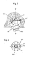
- Fig. 1 und 2 den Bohrer beim Bohren in einer Betonwand in Seitenansicht und Draufsicht,
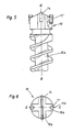
- Fig. 3,4,5,6 Varianten eines Bohrers in einer Darstellung gemäß den Fign. 1,2,
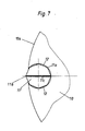
- Fig. 7 einen Ausschnitt aus einem vergrößert dargestellten Bohrer in Draufsicht,
- Fig. 8,9 einen Hartmetallstift aus den Ausführungsbeispielen gemäß den Figuren 1-7 in Seitenansicht und Draufsicht,
- Fig. 10, 11 den koaxialen Hartmetallstift in einer Darstellung entsprechend den Fign. 8,9 und
- Fig. 12 den koaxialen Hartmetallstift gemäß Fig. 10 in einer um 90° gedrehten Position.
- Der im folgenden als 'Bohrer' bezeichnete Drehschlagbohrer ist zum drehschlagenden Bohren in Beton, Gestein und dergleichen mittels eines von Hand führbaren elektropneumatischen Bohrgerätes bestimmt und geeignet. Der Bohrkopf 10 aus Stahl weist wenigstens in diametralen Bereichen seines Außenumfanges etwa zylindrische Mantelflächen 10a auf. Hartmetallstifte 11,11′ sind mit axialen Abschnitten gleichen Durchmessers in zylindrischen Aufnahmebohrungen 12 (Fig. 7) des Bohrkopfes 10 verankert. Sie sind in derartiger Anordnung in den Aufnahmebohrungen aufgenommen und eingelötet, daß wenigstens zwei periphere Hartmetallstifte 11′ über die benachbarte Mantelfläche 10a des Bohrkopfes über ihre gesamte Länge radial vorstehen. Die Hartmetallstifte 11,11′ weisen ein polygonales Querschnittsprofil auf. Sie sind je an der inneren Mantelfläche ihrer Aufnahmebohrung 12 mittels ihrer Längskanten 11a zentriert. In sämtlichen Ausführungsbeispielen stehen die peripheren Hartmetallstifte 11′ derart über ihre gesamte Länge über die benachbarte Mantelfläche 10a des Bohrkopfes radial vor, daß sie entlang ihrer außeren Längskante 11a außerhalb der axialen Projektion des Drehschlagbohrers liegen. In den konkreten Ausführungsbeispielen schließen die peripheren Hartmetallstifte 11′ einen Winkel Alpha zur Bohrerachse a-a, der etwa 3° beträgt.
* mit zwei Längskanten - In den Ausführungsbeispielen der Figuren 1-7 sind die Stirnseiten der Hartmetallstifte 11,11′ durch zwei einen Winkel von ca. 90° zueinander einschließenden Flächen gebildet, die in einer zur Stiftachse b-b senkrecht und zur Bohrerachse a-a radial verlaufenden Schneide aneinandergrenzen. In den zeichnerisch dargestellten Ausführungsbeispielen entspricht das Querschnittsprofil der in den Aufnahmebohrungen 12 aufgenommenen axialen Abschnitte der Hartmetallstifte 11, 11′ einem regelmäßigen Achteck. Der im Bohrkopf in einer stirnseitigen Anformung 10b eingebettete und zentral angeordnete Hartmetallstift 11 ist größer als die übrigen peripheren bzw. nicht zentralen Hartmetallstifte. Der koaxiale Hartmetallstift 11 ist so angeordnet, daß er die übrigen Hartmetallstifte 11′ in axialer Richtung überragt. Die Stirnseite dieses zur Bohrerachse a-a koaxialen Hartmetallstiftes 11 ist durch vier Flächen von gleichem Grundriß gebildet. Diese vier Flächen grenzen unter Bildung von vier Schneiden 11c′ aneinander. Die Schneiden verlaufen entlang von Radialen Y, X (Fig. 11). Zwei Schneiden 11c′ verlaufen entlang einer ersten Radialen Y und schließen einen Winkel von 90° zueinander ein. Zwei weitere Schneiden 11c˝ verlaufen entlang einer zweiten, zur ersten senkrecht stehenden Radialen X und schließen einen Winkel von 135° zueinander ein. In allen Ausführungsbeispielen liegen die Schneiden 11c; 11c′; 11c˝ je* in einer Ebene. Alle Hartmetallstifte 11, 11′ des Bohrkopfes 10 weisen ein Querschnittsprofil auf, das einem regelmäigen Achteck entspricht. Alle peripheren Hartmetallstifte 11′ weisen gleiche Größe auf. Der als Zentrierorgan beim Bohren dienende zentrale Hartmetallstift 11 ist größer als ein zwischen dem zentralen Hartmetallstift 11 und einem peripheren Hartmetallstift 11′ eingebetteter Hartmetallstift 11˝, der so groß wie der periphere Hartmetallstift 11′ oder auch etwas kleiner ausgebildet sein kann.
- Das Ausführungsbeispiel gemäß den Fign. 3 und 4 unterscheidet sich vom Ausführungsbeispiel gemäß den Fign. 1 und 2 im wesentlichen dadurch, daß der Schaft 10a mit einer das Bohrklein aus dem Bohrloch fördernden Förderwendel versehen ist. Das Ausführungsbeispiel der Fign. 5 und 6 unterscheidet sich vom Ausfuhrungsbeispiel der Fign. 3, 4 im wesentlichen dadurch, daß lediglich zwei periphere Hartmetallstifte 11′ und im übrigen eine Hartmetallplatte 14 vorgesehen ist, welche senkrecht zu einer Ebene c-c steht, in welcher die peripheren Hartmetallstifte 11′ liegen.
Claims (9)
sind, daß wenigstens zwei Hartmetallstifte (periphere Hartmetallstifte 11′) über die benachbarte Mantelfläche (10a) des Bohrkopfes (10) radial vorstehen,
dadurch gekennzeichnet, daß periphere Hartmetallstifte (11′) des Bohrkopfes (10) ein polygonales Querschnittsprofil aufweisen und an der inneren Mantelfläche der Aufnahmebohrung (12) mittels ihrer Längskanten (11a) zentriert sind.
Applications Claiming Priority (2)
| Application Number | Priority Date | Filing Date | Title |
|---|---|---|---|
| DE19893919264 DE3919264C2 (de) | 1989-06-13 | 1989-06-13 | Drehschlagbohrer für ein von Hand führbares Bohrgerät |
| DE3919264 | 1989-06-13 |
Publications (3)
| Publication Number | Publication Date |
|---|---|
| EP0402624A2 true EP0402624A2 (de) | 1990-12-19 |
| EP0402624A3 EP0402624A3 (de) | 1991-07-31 |
| EP0402624B1 EP0402624B1 (de) | 1994-07-20 |
Family
ID=6382655
Family Applications (1)
| Application Number | Title | Priority Date | Filing Date |
|---|---|---|---|
| EP19900108763 Expired - Lifetime EP0402624B1 (de) | 1989-06-13 | 1990-05-10 | Drehschlagbohrer für ein von Hand führbares Bohrgerät |
Country Status (2)
| Country | Link |
|---|---|
| EP (1) | EP0402624B1 (de) |
| DE (1) | DE3919264C2 (de) |
Cited By (1)
| Publication number | Priority date | Publication date | Assignee | Title |
|---|---|---|---|---|
| CN109693321A (zh) * | 2019-02-13 | 2019-04-30 | 大同宇林德石墨设备股份有限公司 | 一种快速精准定位毛坯石墨电极端面中心孔的工具 |
Families Citing this family (3)
| Publication number | Priority date | Publication date | Assignee | Title |
|---|---|---|---|---|
| DE4236553A1 (de) * | 1992-10-29 | 1994-05-05 | Hawera Probst Kg Hartmetall | Gesteinsbohrer |
| DE19516270C1 (de) * | 1995-05-09 | 1997-01-30 | Heller Dinklage Gmbh Geb | Bohrwerkzeug |
| WO2013136113A1 (en) * | 2012-03-12 | 2013-09-19 | Flexidrill Limited | Hybrid drill bit |
Family Cites Families (9)
| Publication number | Priority date | Publication date | Assignee | Title |
|---|---|---|---|---|
| DE354355C (de) * | 1922-06-08 | Otto Pohle | Verstellbares zweiteiliges Bohrmesser | |
| FR1174641A (fr) * | 1957-05-07 | 1959-03-13 | Diabor | Procédé pour la fixation de taillants rapportés sur des outils de coupe et outils de coupe, notamment couronnes de forage, ainsi obtenus |
| US3581835A (en) * | 1969-05-08 | 1971-06-01 | Frank E Stebley | Insert for drill bit and manufacture thereof |
| DE2423511A1 (de) * | 1974-05-15 | 1975-11-27 | Krupp Gmbh | Bohrer mit foerderwendel |
| DE2423510A1 (de) * | 1974-05-15 | 1975-11-27 | Krupp Gmbh | Gesteinsbohrer |
| DE2522300A1 (de) * | 1975-05-20 | 1976-12-02 | Krupp Gmbh | Bohrwerkzeug |
| DE2528003A1 (de) * | 1975-06-24 | 1977-01-20 | Krupp Gmbh | Gesteinsbohrer |
| DE3408225A1 (de) * | 1984-03-07 | 1985-09-19 | Richard 5383 Kierspe Karnebogen | Schlagbohrkrone |
| US4966500A (en) * | 1987-09-16 | 1990-10-30 | Mitsubishi Kinzoku Kabushiki Kaisha | Face milling cutter with cutter inserts |
-
1989
- 1989-06-13 DE DE19893919264 patent/DE3919264C2/de not_active Expired - Fee Related
-
1990
- 1990-05-10 EP EP19900108763 patent/EP0402624B1/de not_active Expired - Lifetime
Cited By (1)
| Publication number | Priority date | Publication date | Assignee | Title |
|---|---|---|---|---|
| CN109693321A (zh) * | 2019-02-13 | 2019-04-30 | 大同宇林德石墨设备股份有限公司 | 一种快速精准定位毛坯石墨电极端面中心孔的工具 |
Also Published As
| Publication number | Publication date |
|---|---|
| EP0402624A3 (de) | 1991-07-31 |
| EP0402624B1 (de) | 1994-07-20 |
| DE3919264A1 (de) | 1990-12-20 |
| DE3919264C2 (de) | 1997-01-23 |
Similar Documents
| Publication | Publication Date | Title |
|---|---|---|
| EP1045112B1 (de) | Gesteinsbohrer | |
| DE3820695C2 (de) | Gesteinsbohrer | |
| EP0169402A2 (de) | Gesteinsbohrer | |
| EP0778100B1 (de) | Drehschlag-Wendelbohrer | |
| DE2807353C2 (de) | Schlagend beaufschlagbare Gesteinsbohrkrone | |
| DE69707088T2 (de) | Selbstbohrender ankerbolzen | |
| WO2000029754A1 (de) | Korrosionsfeste schraube mit schneideinsatz | |
| EP1316669A2 (de) | Gesteinbohrwerkzeug | |
| DE19740277B4 (de) | Bohrwerkzeug | |
| DE3742661A1 (de) | Gesteinsbohrer | |
| EP1387923A2 (de) | Bohrkrone | |
| DE10297373T5 (de) | Schneidwerkzeug zur Zerstörung mineralischer und künstlicher Materialien | |
| EP1455978B1 (de) | Schlag- oder hammerbohrer | |
| DE3020284C2 (de) | ||
| EP0402624B1 (de) | Drehschlagbohrer für ein von Hand führbares Bohrgerät | |
| DE3025890A1 (de) | Bohrer fuer bohrhaemmer, insbes. zum bohren in gestein, beton o.dgl. | |
| EP1083295A1 (de) | Bohrwerkzeug | |
| EP1083293B1 (de) | Bohrwerkzeug | |
| DE3408093A1 (de) | Bohrkrone | |
| EP0891832A1 (de) | Bohrer | |
| DE3538191A1 (de) | Gesteinsbohrer | |
| DE3825107C2 (de) | Gesteinsbohrer mit Schneidplatte | |
| DE19545646A1 (de) | Drehschlag-Wendelbohrer | |
| DE3339675A1 (de) | Bohrwerkzeug fuer erdbohrungen | |
| EP0369040A1 (de) | Klebehaken, insbesondere zur Anbringung in Felsgestein oder dergleichen |
Legal Events
| Date | Code | Title | Description |
|---|---|---|---|
| PUAI | Public reference made under article 153(3) epc to a published international application that has entered the european phase |
Free format text: ORIGINAL CODE: 0009012 |
|
| AK | Designated contracting states |
Kind code of ref document: A2 Designated state(s): CH DK FR LI NL |
|
| PUAL | Search report despatched |
Free format text: ORIGINAL CODE: 0009013 |
|
| AK | Designated contracting states |
Kind code of ref document: A3 Designated state(s): CH DK FR LI NL |
|
| 17P | Request for examination filed |
Effective date: 19911017 |
|
| 17Q | First examination report despatched |
Effective date: 19921014 |
|
| GRAA | (expected) grant |
Free format text: ORIGINAL CODE: 0009210 |
|
| AK | Designated contracting states |
Kind code of ref document: B1 Designated state(s): CH DK FR LI NL |
|
| PG25 | Lapsed in a contracting state [announced via postgrant information from national office to epo] |
Ref country code: DK Effective date: 19940720 |
|
| ET | Fr: translation filed | ||
| PLBE | No opposition filed within time limit |
Free format text: ORIGINAL CODE: 0009261 |
|
| STAA | Information on the status of an ep patent application or granted ep patent |
Free format text: STATUS: NO OPPOSITION FILED WITHIN TIME LIMIT |
|
| 26N | No opposition filed | ||
| PGFP | Annual fee paid to national office [announced via postgrant information from national office to epo] |
Ref country code: FR Payment date: 20000517 Year of fee payment: 11 |
|
| PGFP | Annual fee paid to national office [announced via postgrant information from national office to epo] |
Ref country code: CH Payment date: 20000523 Year of fee payment: 11 |
|
| PGFP | Annual fee paid to national office [announced via postgrant information from national office to epo] |
Ref country code: NL Payment date: 20000524 Year of fee payment: 11 |
|
| PG25 | Lapsed in a contracting state [announced via postgrant information from national office to epo] |
Ref country code: CH Free format text: LAPSE BECAUSE OF NON-PAYMENT OF DUE FEES Effective date: 20010609 Ref country code: LI Free format text: LAPSE BECAUSE OF NON-PAYMENT OF DUE FEES Effective date: 20010609 |
|
| PG25 | Lapsed in a contracting state [announced via postgrant information from national office to epo] |
Ref country code: NL Free format text: LAPSE BECAUSE OF NON-PAYMENT OF DUE FEES Effective date: 20011201 |
|
| REG | Reference to a national code |
Ref country code: CH Ref legal event code: PL |
|
| PG25 | Lapsed in a contracting state [announced via postgrant information from national office to epo] |
Ref country code: FR Free format text: LAPSE BECAUSE OF NON-PAYMENT OF DUE FEES Effective date: 20020131 |
|
| NLV4 | Nl: lapsed or anulled due to non-payment of the annual fee |
Effective date: 20011201 |