EP0402628A2 - Halbbiegsamer Stegwellenleiter - Google Patents
Halbbiegsamer Stegwellenleiter Download PDFInfo
- Publication number
- EP0402628A2 EP0402628A2 EP90108840A EP90108840A EP0402628A2 EP 0402628 A2 EP0402628 A2 EP 0402628A2 EP 90108840 A EP90108840 A EP 90108840A EP 90108840 A EP90108840 A EP 90108840A EP 0402628 A2 EP0402628 A2 EP 0402628A2
- Authority
- EP
- European Patent Office
- Prior art keywords
- waveguide
- flexible
- corrugations
- dumbbell
- ridge
- Prior art date
- Legal status (The legal status is an assumption and is not a legal conclusion. Google has not performed a legal analysis and makes no representation as to the accuracy of the status listed.)
- Granted
Links
Images





Classifications
-
- H—ELECTRICITY
- H01—ELECTRIC ELEMENTS
- H01P—WAVEGUIDES; RESONATORS, LINES, OR OTHER DEVICES OF THE WAVEGUIDE TYPE
- H01P3/00—Waveguides; Transmission lines of the waveguide type
- H01P3/12—Hollow waveguides
- H01P3/14—Hollow waveguides flexible
-
- H—ELECTRICITY
- H01—ELECTRIC ELEMENTS
- H01P—WAVEGUIDES; RESONATORS, LINES, OR OTHER DEVICES OF THE WAVEGUIDE TYPE
- H01P3/00—Waveguides; Transmission lines of the waveguide type
- H01P3/12—Hollow waveguides
- H01P3/123—Hollow waveguides with a complex or stepped cross-section, e.g. ridged or grooved waveguides
-
- Y—GENERAL TAGGING OF NEW TECHNOLOGICAL DEVELOPMENTS; GENERAL TAGGING OF CROSS-SECTIONAL TECHNOLOGIES SPANNING OVER SEVERAL SECTIONS OF THE IPC; TECHNICAL SUBJECTS COVERED BY FORMER USPC CROSS-REFERENCE ART COLLECTIONS [XRACs] AND DIGESTS
- Y10—TECHNICAL SUBJECTS COVERED BY FORMER USPC
- Y10T—TECHNICAL SUBJECTS COVERED BY FORMER US CLASSIFICATION
- Y10T29/00—Metal working
- Y10T29/49—Method of mechanical manufacture
- Y10T29/49002—Electrical device making
- Y10T29/49016—Antenna or wave energy "plumbing" making
Definitions
- This invention relates generally to waveguide used for transmission of broadband electromagnetic signals. More particularly, this invention relates to corrugated ridged waveguide of the flexible kind which can be processed in long lengths by a continuous process and has improved power-handling capability.
- waveguide which is rendered flexible by provision of corrugations is used.
- Such waveguide is commercially fabricated by first forming a smooth-walled tube from a tube of conductive metal and thereafter corrugating the tube.
- ridged waveguide typically double-ridge waveguide
- ridges realize a perturbation of the cross-section which provides broader bandwidth between the cut-off frequency of the dominant-mode and the first higher-order mode.
- double-ridge waveguide there are certain disadvantages inherent with the use of double-ridge waveguide. For instance, rectangular double-ridge waveguide, is problematic because the presence of a plurality of corners leads to substantial signal attenuation and the peak-power-handling capability of the waveguide is generally lowered. The sharp corners are also a source of problems in certain manufacturing processes such as electroplating.
- Double-ridge waveguide of the rigid type is also disadvantageous in that it requires precise alignment with the system components in order to function effectively.
- the lack of flexibility of rigid waveguide also poses significant difficulties in handling, storage, and shipping.
- Rigid waveguide is particularly difficult to install and requires accessory coupling components even if the system sections to be linked by the waveguide are slightly displaced axially. More significantly, it is difficult to economically manufacture rigid double-ridge waveguide in long lengths through continuous processing techniques.
- flexible double-ridge waveguide typically of rectangular cross-section
- Flexibility is provided by means of successively formed corrugations of the desired double-ridge cross-sectional shape.
- the manufacturing process involved in fabricating such waveguide is expensive and time consuming because the corrugations are generally non-continuous and have to be formed individually.
- a major disadvantage is that continuous processing is not possible and, accordingly, flexible double-ridge waveguide is commonly available in short lengths only.
- the attenuation factor is increased and voltage-standing-wave-ratios (VSWRs) are degraded to the point where satisfactory performance can be achieved only in very short lengths.
- VSWRs voltage-standing-wave-ratios
- Inherent with the use of short lengths are problems associated with the need for coupling flanges and the associated dry air/gas leakage, potential for intermodulation, resultant VSWR degradation, and need for providing mechanical access to the coupled lengths for alignment purposes.
- Another object of this invention is to provide a flexible waveguide of the above type which provides both relatively high peak-power-handling capability and lower signal attenuation characteristics.
- a semi-flexible double-ridge waveguide comprising a unitary metallic strip formed and welded into a tube and subsequently corrugated and formed into a special cross-sectional shape defined by controllable parameters which can be optimized to provide the waveguide with improved signal handling characteristics as compared to conventional rigid as well as flexible, double-ridge waveguide and yet permits dominant-mode operation across comparable frequency bandwidths.
- the present invention efficiently removes the problems associated with difficulty of installation and the bothersome requirement for precise alignment of components that is inherent to conventional rigid waveguide.
- the present invention provides the much desired combination of flexibility, increased power rating, reduced attenuation and ease of manufacture of long lengths of waveguide by a continuous and relatively uncomplicated and inexpensive process.
- the semi-flexible double-ridge waveguide of this invention has a special cross-section which is designed to be devoid of corners and conforms substantially to a dumbbell-shaped contour defined by a geometric equation in which specific parameters can be correlatively optimized to substantially enhance desired electrical properties of the waveguide.
- the semi-flexible waveguide of this type can be optimized to display electrical characteristics comparable to or better than those available with rigid double-ridge waveguide and retains the characteristics for much longer continuously formed lengths.
- the specially designed waveguide contour results in increased power-handling capability and improved attenuation and VSWR factors for comparable waveguide lengths.
- the effects of the special waveguide shape are further enhanced, according to an embodiment of this invention, by the use of non-annular corrugations having a selected pitch which staggers the disposition of corrugation crests and troughs on opposing sides of the waveguide to such an extent as to maximize the distance between immediately opposing corrugation troughs, thereby increasing the air gap and, consequently, the power-handling capacity of the waveguide.
- the combination of the special dumbbell-shape having optimizable parameters with the selectively staggered corrugations effectively combines the mechanically advantageous flexibility provided by standard flexible double ridge waveguide with the superior electrical characteristics of rigid double-ridge waveguide and increased power-handling capacity relative to conventional flexible annularly corrugated waveguide or rigid double-ridge waveguide.
- FIG. 1 a cross-sectional view of conventional rectangular double-ridge waveguide 10 having a wide dimension generally designated as "a” and a narrow dimension designated as "b".
- a wide dimension
- b narrow dimension
- electromagnetic energy in the rectangular waveguide travels in the fundamental mode with the field intensity being uniformly distributed about the width of the waveguide, with impedance and power-handling being on the "b" dimension.
- the double-ridge rectangular waveguide 10 is provided with a pair of ridges defined by oppositely disposed substantially rectangular constrictions 12, 14 extending lengthwise along the waveguide.
- the reduction at the center of the "b" dimension decreases the characteristic impedance and the power-handling capability of the ridge guide but substantially extends the dominant-mode operational bandwidth. With such a configuration, the electromagnetic energy is highly concentrated near the center of the cross-section.
- Double-ridge waveguide of this type is commonly used with broadband transmission equipment and other applications where extended operational bandwidth and freedom from moding conditions are mandatory.
- rectangular double-ridge waveguide suffers from certain inherent disadvantages, such as higher attenuation and lower peak-power-handling capability, due to the presence of the several corners and added surface area resulting from the rectangular cross-section and the opposing constrictions which define the ridges. These corners also make certain aspects of the manufacturing process, such as electroplating, problematic.
- double-ridge waveguide is typically smooth walled and includes a protective jacket 16 over the metallic conductor constituting the guide.
- a major problem with smooth-walled rectangular double-ridge waveguide is that the inherent inflexibility makes routing and installation difficult and also renders the use of field-attachable flanges impractical due to the necessity for precise alignment between the components being linked.
- double-ridge waveguide is rendered flexible by making the waveguide corrugated along its length while retaining the standard rectangular double-ridge cross-section.
- flexible ridged waveguide is typically formed of annular corrugations 18 with the direction of corrugation being wholly perpendicular to the axis of the waveguide 10.
- the corrugations are formed by successively clamping the smooth-walled waveguide at one end and crimping the guide inwardly along its longitudinal direction to define the corrugations one at a time.
- annular corrugations must be individually formed, a continuous forming process cannot be used, thereby making the flexible waveguide of the type shown in FIG. 2 difficult and expensive to manufacture and also making formation of long lengths impractical. Further, the fully flexible nature of the waveguide accruing from the annular nature of the grooves dramatically increases the attenuation factor of the waveguide in use. Another problem is that the VSWR remains within acceptable limits only for restricted lengths of waveguide.
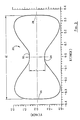
- FIG. 3 there is shown a(cross-sectional view of(an improved(semi-flexible double-ridge waveguide according to a preferred embodiment of the present invention.
- dumbbell shape essentially corresponds to that of a rectangular waveguide having oppositely disposed ridges 22, 24 which are not of the rectangular cross-sectional shape shown in FIGS. 1, 2 but instead are of a substantially bell-shaped cross-section which extends to generally convex ends 26, 28 of the waveguide cross-section defined about the major axis.
- the polar equation (1) defines the contour in such a way that the upturned ends of the bell-shaped ridges smoothly merge with the cross-sectional ends of the waveguide, thereby avoiding the presence of any corners or abrupt protrusions.
- the contour of FIG. 3 represents the cross-sectional shape of the waveguide 20 according to a preferred embodiment where the parameters "u”, “v” and “p” are selected to be 0.702 ⁇ , 0.128 ⁇ , and 3.40, respectively, based on a dominant-mode operational bandwidth of 7.5 - 18.0 GHz.
- FIG. 4 is an illustration of how a variation in the parameter "p", while keeping “u” and “v” constant (at 0.70 ⁇ and 0.12 ⁇ , respectively), affects the cross-sectional shape of the waveguide contour. More specifically, increasing values of "p" increase the extent to which the waveguide contour strays away from the minor axis before merging with the cross-sectional ends.
- FIG. 4 shows the variation only along the first quadrant of the overall contour cross-section; it will be apparent that a similar variation in shape also applies to the remaining three quadrants.
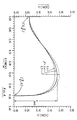
- FIG. 5 there is shown a graphical illustration of the increase in bandwidth realized by the dumbbell-shaped waveguide of FIGS. 3 and 4. Shown therein is a pair of graphs representing the variation in bandwidth of the waveguide with increasing values pf the parameter "p" for different ratios of the length of the major and minor axes "u", "v", respectively.
- the waveguide bandwidth is defined as the ratio of the cutoff frequency (F c2 ) of the modified TE20 mode to the cut-off frequency (F c1 ) of the modified TE10 mode.
- any increase in the value of the parameter "p" brings about an increase in bandwidth defined by the ratio F c2 /F c1 , with the range of bandwidth being inversely proportional to the selected aspect ratio (v/u) for the contour.
- equation (1) In order for the desired dumbbell-shaped waveguide contour to be adequately defined, equation (1) must be subject to two constraints:
- the waveguide contour is optimized conveniently by considering the change in electrical characteristics produced by variations in the parameters "u”, “v” and “p” and determining, preferably through some form of computer-based approximation technique, the range of values for these parameters which provides the largest possible dominant-mode operational bandwidth and the least amount of signal attenuation. This determination can be supplemented by actually measuring the desired electrical characteristics to determine the optimum value or range of values of the parameters required to define a waveguide contour which is optimized for the desired bandwidth of dominant-mode operation, selected attenuation characteristics, etc.
- the calculation of the cutoff frequencies of the first two modes, namely the modified TE10 and TE20 modes, for defining the operational bandwidth and the accompanying attenuation can be performed conveniently by employing one of several computer techniques, such as polynomial approximation or finite element analysis, which are known in the industry for analyzing waveguide shapes of arbitrary cross-sections.
- polynomial approximation or finite element analysis which are known in the industry for analyzing waveguide shapes of arbitrary cross-sections.
- One exemplary technique is described by R. M. Bulley in a paper entitled “Analysis of the arbitrarily shaped waveguide by polynomial approximation", as published in IEEE Transactions on Microwave Theory and Techniques , Vol. MTT-18, pp. 1022-1028, Dec. 1970.
- a dumbbell-shaped waveguide was optimized for the 7.5 - 18.0 GHz frequency bandwidth commonly used nowadays for defense-related tele-communication purposes.
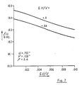
- FIG. 7 is a graphical illustration of the correlation between the length of the major and minor axes "u” and “v”, respectively, and the cut-off frequency of the first higher-order mode. As shown therein, the cut-off frequency F c2 gradually decreases with increasing values of "u” when the parameter "v” is maintained constant. Two such correlation graphs are shown for incremental differences in the parameter "u” being equal to 0.0 and 0.04.
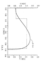
- FIG. 8 is a similar graphical illustration showing the correlation between the dominant mode cut-off frequency and incremental differences in the length of the major axis, i.e., the parameter "u”, while maintaining the length of the minor axis, i.e., the parameter "v", at a predetermined constant value.
- Three such correlation curves are shown in FIG. 8 for predetermined constant values of 0.0, +0.04 and -0.04 of the parameter "v".
- the parameters "u”, "v” and “p" of the semi-flexible waveguide defined by equation (1) can, according to this invention, be controllably varied to realize significantly improved dominant-mode operational frequency bandwidth and reduced attenuation factor compared to that of standard rectangular or circular waveguide.
- such a waveguide can be optimized to provide operational dominant-mode bandwidths comparable to or better than that of standard ridge waveguide while, at the same time, having an attenuation factor significantly lower than that of any commercially available double-ridge waveguide.
- FIG. 9 shows graphical representations of curves based on theoretical and experimental data reflecting the attenuation associated with the semi-flexible waveguide of this invention and the variation in attenuation across the desired frequency bandwidth.
- the waveguide used for these measurements was optimized for operation across a frequency bandwidth extending between 6.0 - 14.4 GHz.
- the curve A represents the theoretically calculated attenuation versus frequency response for the semi-flexible waveguide, as determined on the basis of polynomial approximation or like techniques.
- the theoretical attenuation remains substantially within the range of 4.0 - 5.5 dBs/100 ft. across the frequency band of interest.
- the experimentally measured attenuation as represented by curves B and C, remains substantially within the ranges of 4.0 - 5.0 dBs/100 ft. and 4.0 - 6.0 dBs/100 ft., respectively, at the lower and upper ends of the measurement scale.
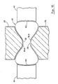
- FIG. 10 there is shown a cross-sectional view of a preferred arrangement for imparting the special dumbbell-shaped contour to form the semi-flexible waveguide of the shape shown in FIG. 3.
- the cross-section of the waveguide 30 is defined by the oppositely disposed bell-shaped ridge sections 32, 34 and the generally convex end sections 42 and 44 which effectively link the ridges to form the overall dumbbell-shaped contour defined by polar equation (1) using selected values for parameters "u", "v" and "p".
- the choice of these parameters is based upon the desired dominant-mode bandwidth and minimized attenuation, as most advantageously determined by computer-based polynomial approximation, finite element analysis or other like technique.
- the waveguide contour is formed from a continuous length of corrugated circular tube by means of a pair of ridge wheels 36, 38 which have driving faces 36A, 36B possessing a shape substantially corresponding, according to a converse relationship, to the bell-shaped contour of the waveguide ridges 32, 34.
- the ridge wheels are simultaneously brought into rotating contact on diametrically opposite external faces of the tubular waveguide as the waveguide is continuously moved across the rotating ridge wheels in a transverse direction.
- a pair of diametrically opposed support surfaces 40, 41 having concave faces generally corresponding, according to a converse relationship, to the shape of the convex end sections 42, 44 are brought into supporting contact with the end sections.
- the simultaneous positive driving impact of the ridge wheels 36, 38 on diametrically opposite surfaces of the waveguide forms the two bell-shaped ridges 32, 34, and the support provided by the concave surfaces 40, 41 on the remaining opposite surfaces of the waveguide prevents any uneven expansion of the waveguide under the driving impact of the ridge wheels.
- the ridge wheels and the support surfaces in conjunction with each other, generate the overall dumbbell-shaped contour defined by the optimized polar equation (1).
- the waveguide of FIG. 3 is rendered semi-flexible by the use of continuously linked corrugations which allow a certain degree of flexibility without rendering the waveguide completely flexible like conventional flexible waveguide having discrete annular corrugations.
- the waveguide of the desired cross-sectional shape is formed with helical corrugations which provide only a restricted amount of flexibility. In effect, such a waveguide is truly "semi-flexible" and has distinct advantages over both rigid double-ridge waveguide and flexible double-ridge waveguide.
- the semi-flexible waveguide is significantly easier to be routed and installed in confined areas and flexible enough to be adapted to minor length adjustments which are essential to accommodate dimensional tolerances both in the waveguide itself and in the area where the waveguide is to be installed.
- the restricted flexibility also keeps signal attenuation down and makes practical the use of waveguide lengths substantially longer than would be possible with completely flexible waveguide.
- Such waveguide is typically manufactured by forming a tube from a strip of conductive metal (typically copper or aluminum), welding the tube and shaping it to approximate rectangularity, and forming annular corrugations thereupon by clamping the smooth-walled waveguide at one end and successively crimping the waveguide inwardly along its longitudinal direction toward the clamped end to define the corrugations one at a time.
- conductive metal typically copper or aluminum
- FIG. 11A A cross-sectional view of conventional annularly corrugated ridged waveguide is illustrated at FIG. 11A.
- the waveguide 50 has annular corrugations 52 spaced apart by a distance "S" (the pitch) and extending to a depth "d” defined by the distance between successive crests 54 and troughs 55 of the corrugations. Because the corrugations are annularly formed, the corrugation crests 54 on one wall of the waveguide are disposed diametrically opposite the corrugation crests 56 on the other wall of the waveguide and vice versa.
- the breakdown air gap which defines the power-handling capability of the waveguide and which is a function of the minimum distance between opposing internal surfaces of the waveguide, is restricted for a given internal waveguide diameter.
- the annular corrugations are spaced apart by a pitch distance of "S" which is comparable to the corrugation depth "d” and the ratio of corrugation depth to pitch is typically 0.8 or more.
- the air gap distance, as defined by the space between opposing corrugation troughs 55 and 57 is designated as "X" in FIG. 11A. Even if the annular corrugations were to be provided in the form of spaced-apart groups in order to restrict flexibility, the breakdown air gap and, hence, the maximum power rating of the waveguide remains restricted by the distance "x".
- the power-handling capability of waveguide having the dumbbell-shaped contour of FIG. 3 is increased by using continuous non-annular corrugations which are relatively widely spaced compared to the corrugation depth, as shown in FIG. 11B.
- the dumbbell-shaped contour generated on the basis of polar equation 1 is devoid of the sharp edges characteristic of conventional rectangular double-ridge waveguide; the rounded edges (see FIG. 3) avoid the excessive power loss resulting from obstructions presented by sharp corners in the waveguide cavity.
- the power rating of the waveguide is further increased by the use of corrugations which are helically configured in such a way that the corrugation crests and troughs on one wall of the waveguide are staggered relative to those on the opposite wall.
- the waveguide 60 is formed of helical corrugations 62 which are spaced apart at a pitch distance "S1", which is substantially larger than the corrugation depth "d1".
- the pitch "S1" was selected to be about 0.18 ⁇ and the depth "d1" was selected to be about .04 ⁇ so that the depth-to-pitch ratio was about 0.22.
- the helical nature of the corrugations effectively staggers the corrugation crests 64 and troughs 65 on one wall of the waveguide relative to those on the opposing wall.
- the air gap distance "Y" is defined between helical corrugation troughs 65 on the top wall of the waveguide 60 and the corresponding troughs 67 on the bottom wall and is larger than the distance "X" that would exist if the corrugations were to be annular.
- This increase in air gap distance is significant in the case of double-ridge waveguide of the type shown in FIG. 3 because the constrictions defined by the bell-shaped ridges intrinsically reduce the air gap substantially to the point where the air gap becomes comparable to the pitch of the corrugations. Under such conditions, even a small increase in air gap resulting from the expansion of the distance between opposing corrugation troughs and crests can produce a noticeable increase in the maximum power rating of the waveguide.
- FIG. 11B represents the case where the relative staggering of opposing corrugations is by the maximum extent possible between the opposite walls of the waveguide. More specifically, in FIG. 11B, the staggering is such that the corrugation troughs 65 on the top wall of the waveguide 60 are disposed immediately opposite the corrugation crests 66 on the bottom wall. However, the breakdown air gap is increased even if the corrugations are staggered to a lesser extent than that shown in FIG. 11B so that corrugations crests on one wall do not directly face the corrugation troughs on the opposite wall, but are merely displaced relative to each other. It will be apparent that any staggering of corrugations relative to the disposition illustrated in FIG. 11A realizes a distance "y" which is greater than the distance "x", thereby increasing the waveguide air gap and power-handling capability.
- the combined use of an increased ratio of corrugation depth to corrugation pitch and the helical staggering of corrugation crests and troughs in a waveguide having the optimizable dumbbell-shaped cross-section realizes the much desired combination of flexibility and improved electrical characteristics, including increased power-handling capability.
- the helically corrugated waveguide having the dumbbell-shaped cross-section is conveniently manufactured in long lengths by the use of a continuous process wherein the helically corrugated waveguide is first formed by the use of continuous rotating contact between an appropriately shaped corrugating die or tool and the external surface of waveguide formed by folding and longitudinally welding a strip of metal into a substantially circular tube.
- the tube is continuously advanced and the corrugating tool is moved wholly transversely in proper synchronism with the advancing motion of the tube.
- the helically corrugated waveguide is then provided with the dumbbell-shaped cross-section using the procedure described above for using the shaping wheel arrangement of FIG. 10 to impart the shape defined by equation (1).
Landscapes
- Waveguides (AREA)
Applications Claiming Priority (2)
| Application Number | Priority Date | Filing Date | Title |
|---|---|---|---|
| US07/365,598 US4978934A (en) | 1989-06-12 | 1989-06-12 | Semi-flexible double-ridge waveguide |
| US365598 | 1989-06-12 |
Publications (3)
| Publication Number | Publication Date |
|---|---|
| EP0402628A2 true EP0402628A2 (de) | 1990-12-19 |
| EP0402628A3 EP0402628A3 (de) | 1992-01-08 |
| EP0402628B1 EP0402628B1 (de) | 1996-10-02 |
Family
ID=23439529
Family Applications (1)
| Application Number | Title | Priority Date | Filing Date |
|---|---|---|---|
| EP90108840A Expired - Lifetime EP0402628B1 (de) | 1989-06-12 | 1990-05-10 | Halbbiegsamer Stegwellenleiter |
Country Status (7)
| Country | Link |
|---|---|
| US (1) | US4978934A (de) |
| EP (1) | EP0402628B1 (de) |
| JP (1) | JPH0388401A (de) |
| AU (1) | AU628973B2 (de) |
| CA (1) | CA2015533C (de) |
| DE (1) | DE69028735T2 (de) |
| IL (1) | IL94395A (de) |
Cited By (1)
| Publication number | Priority date | Publication date | Assignee | Title |
|---|---|---|---|---|
| WO2015140036A1 (de) * | 2014-03-19 | 2015-09-24 | Paul Vahle Gmbh & Co. Kg | Schlitzhohlleiter |
Families Citing this family (22)
| Publication number | Priority date | Publication date | Assignee | Title |
|---|---|---|---|---|
| WO2002052674A1 (en) * | 2000-12-21 | 2002-07-04 | Paratek Microwave, Inc. | Waveguide to microstrip transition |
| KR100561634B1 (ko) * | 2004-08-03 | 2006-03-15 | 한국전자통신연구원 | 유도성 아이리스를 갖는 전계면 결합망 구조의 도파관다이플렉서 |
| KR101720591B1 (ko) | 2010-10-04 | 2017-03-29 | 삼성전자주식회사 | 릿지 구조의 테라헤르츠 발진회로 |
| AU2011314378A1 (en) * | 2010-10-15 | 2013-05-02 | Searete Llc | Surface scattering antennas |
| US8952678B2 (en) | 2011-03-22 | 2015-02-10 | Kirk S. Giboney | Gap-mode waveguide |
| RU2498465C1 (ru) * | 2012-05-12 | 2013-11-10 | Открытое акционерное общество "Концерн радиостроения "Вега" | Шарнирное волноводное соединение |
| US9385435B2 (en) | 2013-03-15 | 2016-07-05 | The Invention Science Fund I, Llc | Surface scattering antenna improvements |
| US9647345B2 (en) | 2013-10-21 | 2017-05-09 | Elwha Llc | Antenna system facilitating reduction of interfering signals |
| US9923271B2 (en) | 2013-10-21 | 2018-03-20 | Elwha Llc | Antenna system having at least two apertures facilitating reduction of interfering signals |
| US9935375B2 (en) | 2013-12-10 | 2018-04-03 | Elwha Llc | Surface scattering reflector antenna |
| US9825358B2 (en) | 2013-12-17 | 2017-11-21 | Elwha Llc | System wirelessly transferring power to a target device over a modeled transmission pathway without exceeding a radiation limit for human beings |
| US10256548B2 (en) | 2014-01-31 | 2019-04-09 | Kymeta Corporation | Ridged waveguide feed structures for reconfigurable antenna |
| US10431899B2 (en) | 2014-02-19 | 2019-10-01 | Kymeta Corporation | Dynamic polarization and coupling control from a steerable, multi-layered cylindrically fed holographic antenna |
| US9843103B2 (en) | 2014-03-26 | 2017-12-12 | Elwha Llc | Methods and apparatus for controlling a surface scattering antenna array |
| US9448305B2 (en) | 2014-03-26 | 2016-09-20 | Elwha Llc | Surface scattering antenna array |
| US9853361B2 (en) | 2014-05-02 | 2017-12-26 | The Invention Science Fund I Llc | Surface scattering antennas with lumped elements |
| US9711852B2 (en) | 2014-06-20 | 2017-07-18 | The Invention Science Fund I Llc | Modulation patterns for surface scattering antennas |
| US10446903B2 (en) | 2014-05-02 | 2019-10-15 | The Invention Science Fund I, Llc | Curved surface scattering antennas |
| US9882288B2 (en) | 2014-05-02 | 2018-01-30 | The Invention Science Fund I Llc | Slotted surface scattering antennas |
| US10361481B2 (en) | 2016-10-31 | 2019-07-23 | The Invention Science Fund I, Llc | Surface scattering antennas with frequency shifting for mutual coupling mitigation |
| US10892553B2 (en) | 2018-01-17 | 2021-01-12 | Kymeta Corporation | Broad tunable bandwidth radial line slot antenna |
| WO2022232822A2 (en) * | 2021-04-28 | 2022-11-03 | Optisys, Inc. | Evanescent mode waveguide filter |
Family Cites Families (7)
| Publication number | Priority date | Publication date | Assignee | Title |
|---|---|---|---|---|
| DE1490804A1 (de) * | 1964-08-06 | 1969-07-17 | Telefunken Patent | Belastete Hohlrohrleitung |
| DE1690246A1 (de) * | 1967-02-01 | 1971-05-06 | Telefunken Patent | Steg-Hohlleiter |
| DE1790171C2 (de) * | 1968-09-21 | 1974-08-01 | Telefunken Patentverwertungsgesellschaft Mbh, 7900 Ulm | Breitbandiger Hohlleiter |
| US3822411A (en) * | 1971-05-06 | 1974-07-02 | Andrew Corp | Corrugated waveguide construction |
| DE2458240A1 (de) * | 1973-12-08 | 1975-09-04 | Furukawa Electric Co Ltd | Verfahren und anlage zur herstellung von geriffelten wellenleitern |
| US3974467A (en) * | 1974-07-30 | 1976-08-10 | The Furukawa Electric Co., Ltd. | Long flexible waveguide |
| US3945552A (en) * | 1974-12-09 | 1976-03-23 | Furukawa Electric Co., Ltd. | Method and apparatus for forming a corrugated waveguide |
-
1989
- 1989-06-12 US US07/365,598 patent/US4978934A/en not_active Expired - Fee Related
-
1990
- 1990-04-26 CA CA002015533A patent/CA2015533C/en not_active Expired - Fee Related
- 1990-05-10 DE DE69028735T patent/DE69028735T2/de not_active Expired - Fee Related
- 1990-05-10 EP EP90108840A patent/EP0402628B1/de not_active Expired - Lifetime
- 1990-05-15 IL IL9439590A patent/IL94395A/en not_active IP Right Cessation
- 1990-05-18 AU AU55144/90A patent/AU628973B2/en not_active Ceased
- 1990-06-12 JP JP2153844A patent/JPH0388401A/ja active Pending
Cited By (1)
| Publication number | Priority date | Publication date | Assignee | Title |
|---|---|---|---|---|
| WO2015140036A1 (de) * | 2014-03-19 | 2015-09-24 | Paul Vahle Gmbh & Co. Kg | Schlitzhohlleiter |
Also Published As
| Publication number | Publication date |
|---|---|
| JPH0388401A (ja) | 1991-04-12 |
| CA2015533A1 (en) | 1990-12-12 |
| IL94395A (en) | 1994-07-31 |
| AU628973B2 (en) | 1992-09-24 |
| DE69028735D1 (de) | 1996-11-07 |
| US4978934A (en) | 1990-12-18 |
| AU5514490A (en) | 1990-12-13 |
| CA2015533C (en) | 1994-06-28 |
| EP0402628A3 (de) | 1992-01-08 |
| EP0402628B1 (de) | 1996-10-02 |
| DE69028735T2 (de) | 1997-02-13 |
| IL94395A0 (en) | 1991-03-10 |
Similar Documents
| Publication | Publication Date | Title |
|---|---|---|
| US4978934A (en) | Semi-flexible double-ridge waveguide | |
| EP0145292B1 (de) | Rechteckig-elliptischer Übergangshohlleiter | |
| JP7272778B2 (ja) | 折り返し導波路低速波構造を用いる進行波管用の内部負荷 | |
| CA1097412A (en) | Microwave device for converting a wave guide structure into microstrip conductor structure | |
| US3691488A (en) | Radiating coaxial cable and method of manufacture thereof | |
| EP0189963B1 (de) | Superelliptische Wellenleiterverbindung | |
| US3909757A (en) | Leaky coaxial cable | |
| US2676257A (en) | Microwave antenna array | |
| US8179213B2 (en) | Electromagnetic wave transmission medium comprising a flexible circular tube with a solid circle shaped ridge disposed therein | |
| US3331400A (en) | Flexible waveguide | |
| JPH08195605A (ja) | 導波管 | |
| US6292072B1 (en) | Radiating coaxial cable having groups of spaced apertures for generating a surface wave at a low frequencies and a combination of surface and radiated waves at higher frequencies | |
| US3777045A (en) | High voltage system, particularly cable | |
| CN1126193C (zh) | 高频发射同轴电缆 | |
| US3020498A (en) | Coupled waveguides | |
| US3822411A (en) | Corrugated waveguide construction | |
| KR20010020573A (ko) | 스터브가 장착된 나선형 안테나 | |
| ART | US. Patent Dec. 18, 1990 Sheet 1 of 10 4,978,934 | |
| CN116565550B (zh) | 一种慢波线共面频扫天线阵 | |
| US4871950A (en) | Wide band device for coupling between the delay line of a travelling wave tube and the external circuit transmitting the energy of the tube | |
| JPH0680965B2 (ja) | 誘電体装荷テ−パ導波管 | |
| JP2003051713A (ja) | 漏洩同軸ケーブル | |
| AU2019290034B2 (en) | An electromagnetic coupler | |
| CN219498171U (zh) | 一种小型化宽带加脊波导天线 | |
| EP4372770A1 (de) | Spule und verfahren zur herstellung einer spule |
Legal Events
| Date | Code | Title | Description |
|---|---|---|---|
| PUAI | Public reference made under article 153(3) epc to a published international application that has entered the european phase |
Free format text: ORIGINAL CODE: 0009012 |
|
| AK | Designated contracting states |
Kind code of ref document: A2 Designated state(s): DE FR GB IT NL |
|
| RAP1 | Party data changed (applicant data changed or rights of an application transferred) |
Owner name: ANDREW A.G. |
|
| PUAL | Search report despatched |
Free format text: ORIGINAL CODE: 0009013 |
|
| AK | Designated contracting states |
Kind code of ref document: A3 Designated state(s): DE FR GB IT NL |
|
| 17P | Request for examination filed |
Effective date: 19920317 |
|
| 17Q | First examination report despatched |
Effective date: 19940127 |
|
| GRAH | Despatch of communication of intention to grant a patent |
Free format text: ORIGINAL CODE: EPIDOS IGRA |
|
| GRAH | Despatch of communication of intention to grant a patent |
Free format text: ORIGINAL CODE: EPIDOS IGRA |
|
| GRAA | (expected) grant |
Free format text: ORIGINAL CODE: 0009210 |
|
| AK | Designated contracting states |
Kind code of ref document: B1 Designated state(s): DE FR GB IT NL |
|
| REF | Corresponds to: |
Ref document number: 69028735 Country of ref document: DE Date of ref document: 19961107 |
|
| ITF | It: translation for a ep patent filed | ||
| ET | Fr: translation filed | ||
| PLBE | No opposition filed within time limit |
Free format text: ORIGINAL CODE: 0009261 |
|
| STAA | Information on the status of an ep patent application or granted ep patent |
Free format text: STATUS: NO OPPOSITION FILED WITHIN TIME LIMIT |
|
| 26N | No opposition filed | ||
| PGFP | Annual fee paid to national office [announced via postgrant information from national office to epo] |
Ref country code: DE Payment date: 19990507 Year of fee payment: 10 |
|
| PGFP | Annual fee paid to national office [announced via postgrant information from national office to epo] |
Ref country code: FR Payment date: 19990511 Year of fee payment: 10 |
|
| PGFP | Annual fee paid to national office [announced via postgrant information from national office to epo] |
Ref country code: GB Payment date: 19990512 Year of fee payment: 10 |
|
| PGFP | Annual fee paid to national office [announced via postgrant information from national office to epo] |
Ref country code: NL Payment date: 19990531 Year of fee payment: 10 |
|
| PG25 | Lapsed in a contracting state [announced via postgrant information from national office to epo] |
Ref country code: GB Free format text: LAPSE BECAUSE OF NON-PAYMENT OF DUE FEES Effective date: 20000510 |
|
| PG25 | Lapsed in a contracting state [announced via postgrant information from national office to epo] |
Ref country code: NL Free format text: LAPSE BECAUSE OF NON-PAYMENT OF DUE FEES Effective date: 20001201 |
|
| GBPC | Gb: european patent ceased through non-payment of renewal fee |
Effective date: 20000510 |
|
| PG25 | Lapsed in a contracting state [announced via postgrant information from national office to epo] |
Ref country code: FR Free format text: LAPSE BECAUSE OF NON-PAYMENT OF DUE FEES Effective date: 20010131 |
|
| NLV4 | Nl: lapsed or anulled due to non-payment of the annual fee |
Effective date: 20001201 |
|
| PG25 | Lapsed in a contracting state [announced via postgrant information from national office to epo] |
Ref country code: DE Free format text: LAPSE BECAUSE OF NON-PAYMENT OF DUE FEES Effective date: 20010301 |
|
| REG | Reference to a national code |
Ref country code: FR Ref legal event code: ST |
|
| PG25 | Lapsed in a contracting state [announced via postgrant information from national office to epo] |
Ref country code: IT Free format text: LAPSE BECAUSE OF NON-PAYMENT OF DUE FEES Effective date: 20050510 |