EP0402664B1 - Verfahren und Vorrichtung zur Herstellung eines Florgewebes - Google Patents
Verfahren und Vorrichtung zur Herstellung eines Florgewebes Download PDFInfo
- Publication number
- EP0402664B1 EP0402664B1 EP90109659A EP90109659A EP0402664B1 EP 0402664 B1 EP0402664 B1 EP 0402664B1 EP 90109659 A EP90109659 A EP 90109659A EP 90109659 A EP90109659 A EP 90109659A EP 0402664 B1 EP0402664 B1 EP 0402664B1
- Authority
- EP
- European Patent Office
- Prior art keywords
- tuft
- yarn
- slot
- web
- length
- Prior art date
- Legal status (The legal status is an assumption and is not a legal conclusion. Google has not performed a legal analysis and makes no representation as to the accuracy of the status listed.)
- Expired - Lifetime
Links
Images
Classifications
-
- D—TEXTILES; PAPER
- D04—BRAIDING; LACE-MAKING; KNITTING; TRIMMINGS; NON-WOVEN FABRICS
- D04H—MAKING TEXTILE FABRICS, e.g. FROM FIBRES OR FILAMENTARY MATERIAL; FABRICS MADE BY SUCH PROCESSES OR APPARATUS, e.g. FELTS, NON-WOVEN FABRICS; COTTON-WOOL; WADDING ; NON-WOVEN FABRICS FROM STAPLE FIBRES, FILAMENTS OR YARNS, BONDED WITH AT LEAST ONE WEB-LIKE MATERIAL DURING THEIR CONSOLIDATION
- D04H11/00—Non-woven pile fabrics
-
- D—TEXTILES; PAPER
- D05—SEWING; EMBROIDERING; TUFTING
- D05C—EMBROIDERING; TUFTING
- D05C15/00—Making pile fabrics or articles having similar surface features by inserting loops into a base material
Definitions
- the present invention relates to the manufacture of a pile fabric by attaching tuft-forming lengths of yarn to a pre-formed web.
- apparatus comprising guide means for guiding a web along a path through on attaching station, tuft-control means defining at the attaching station a slot, the slot being arranged with its length transverse to the length of said path at the attaching station, and pressing means for pressing yarn through the slot onto the web at the attaching station, wherein at least one of the pressing means and the tuft-control means has a yarn-receiving groove and wherein the length of the groove is transverse to both the length of said path at the attaching station and the length of the slot.
- Yarn which moves along a yarn-receiving groove during pressing of the yarn onto the web will tend to remain in the groove so that the position of that part of a length of yarn which remains in the groove can be controlled within a small tolerance. Accordingly, particularly in a case where a further portion of the length of yarn is embedded in a layer of adhesive on the web and the adhesive is then permitted to stiffen, a required pattern can be reproduced with greater accuracy than can be achieved with the method and apparatus disclosed in GB1,422,524A.
- the apparatus may be suitable for implanting a complete row of tufts during a single movement of the pressing means through the slot towards the web.
- the pressing means extends along substantially the entire useful length of the slot.
- the apparatus may be arranged for implanting tufts of one row in succession.
- the tuft-control means preferably comprises a dividing member which divides the slot transversely of its length into portions which are arranged sequentially along the slot. The pressing means would then be localised to enter one only of said portions at a time.
- a method of manufacturing a pile fabric wherein a web is moved through an attaching station and tuft-forming lengths of yarn are applied to the web at the attaching station, the attitude and position of the lengths relative to the web being controlled during application of the lengths to the web by tuft-control means at the attaching station, characterised in that a yarn-receiving groove is formed in the tuft-control means and in that a tuft-forming length of yarn is moved into the groove whilst still spaced from the web and remains in the groove whilst the length of yarn is moved to the web.
- each tuft-forming length of yarn is bent into a U-shape and forms a double tuft, a pair of yarn-receiving grooves is farmed in the tuft-control means and the limbs of the double tuft are received in respective ones of said pair of grooves.
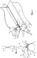
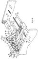
- the apparatus illustrated in Figures 1 and 2 comprises guide means for guiding a web 10 along a path which extends from a bulk supply of the web (not shown) through an attaching station shown in Figure 1 to a take-up roll (also not shown).
- the guide means includes a support 11 disposed at the attaching station.
- the support has a flat surface 12 on which the web 10 rests at the attaching station.
- the flat surface 12 lies between curved surface portions 13 and 14 of the support, across which curved surface portions the web 10 approaches and leaves the flat surface 12.
- the guide means for the web may be arranged generally as described and illustrated in GB1,422,524A and may include an accumulator for accumulating a variable length of the web and means for maintaining a required tension in the web.
- the apparatus includes a heater 15 for heating the adhesive upstream of the attaching station.
- the heater is disposed immediately adjacent to the path along which the web 10 approaches the support 11 and is arranged to transfer heat to the adhesive layer through the web 10. This establishes a temperature gradient in the layer of adhesive such that the viscosity of the adhesive is lower immediately adjacent to the web 10 and is higher at the exposed surface of the layer of adhesive.
- tuft-control means for controlling tufts as these are implanted in the layer of adhesive on the web 10 and immediately after the tufts have been implanted.
- the tuft-control means includes upstream and downstream control members 16 and 17 respectively which are spaced apart in a direction transverse to the direction of movement of the web 10 to define a slot 18 extending across the entire width of the web.
- the slot lies directly above the flat surface 12 of the support 11.
- the slot 18 is rectilinear and is of uniform width.
- the opposite boundary surfaces of the slot are flat, mutually parallel and perpendicular to the flat surface 12.
- delivery means for delivering a row of tuft-forming lengths of yarn to the attaching station.
- delivery means for delivering a row of tuft-forming lengths of yarn to the attaching station.
- the particular example of delivery means illustrated in Figure 1 is a set of grippers 19.
- a known source of yarns for example a number of spools, may be provided for presenting yarn ends for seizing by the grippers 19.
- a suitable source of yarns and suitable means for operating the grippers are disclosed in GB 1,422,524A.
- the apparatus also includes a presser member 20 mounted for reciprocation towards and away from the support 11 through the slot 18.
- Drive means is provided for moving the presser member between the raised position illustrated in Figure 1 and a lowered position in which the presser member extends downwardly through the slot substantially to the level of the layer of adhesive on that part of the web which rests on the flat surface 12.
- the presser member 20 In the raised position, the presser member 20 is spaced sufficiently far above the control members 16 and 17 to permit the grippers 19 to move across the top of the slot 18 to the source of yarn ends and to return, drawing portions of yarn across the slot.
- the presser member 20 is rectilinear and has a length substantially equal to the length of the slot 18.
- the width of the presser member is slightly less than the width of the slot, so that the presser member can move into the slot with clearance between the presser member and the control members 16 and 17.
- each of the upstream and downstream faces of the presser member 20 there is formed a respective row of yarn-receiving grooves 21.
- the grooves are arranged in pairs with one groove on the upstream face of the presser member being aligned in the direction of travel of the web 10 through the attaching station with a corresponding groove in the downstream face of the presser member.
- the number of pairs of grooves corresponds to the number of lengths of yarn which form a single row of double tufts on the web.
- the pitch of the grooves along each row is equal to the pitch of the tufts along the rows of the finished pile fabric.
- Each of the grooves 21 is arranged with its length perpendicular to the length of the slot 18 and perpendicular to the direction of travel of the web 10 through the attaching station.
- the tuft- control means further comprises a pusher 22 disposed at the downwardly facing surface of the upstream control member 16 and arranged for reciprocation between a position in which the pusher lies entirely beneath the upstream control member and a projected position in which the pusher extends across the bottom of the slot 18 and overlaps with a downwardly projecting lip 23 formed on the downstream control member 17 immediately adjacent to the slot.
- the drive means for advancing the web 10, driving the spools or other source of yarn, reciprocating and operating the grippers 19, operating a knife (not shown) to sever the tuft-forming lengths of yarn from the bulk supply, for reciprocating the presser member 20 and for reciprocating the pusher 22 may be substantially as disclosed in GB1,422,524.
- the grippers 19 are advanced past the slot 18 to seize the ends of yarn from the bulk supply of yarns.
- the grippers then return to draw tuft-forming lengths of yarn from the source. These lengths are severed from the bulk supply in a known manner by an automatically operated knife.
- the lengths of yarn are drawn across the slot 18 until a mid-portion of each length is directly above the slot.
- the presser member 20 then descends to engage each length of yarn and to push the mid-portion of each length through the slot 18 into the layer of adhesive on the web 10. Opposite end portions of each length follow the mid-portion through the slot. However, end portions of the lengths remain in the slot 18 when the mid-portion has been embedded in the layer of adhesive. This ensures that the limbs of each newly implanted double tuft have an upstanding relation with respect to the web.
- the yarn ends are presented by the bulk supply in positions such that, when the tuft-forming lengths of yarn are drawn by the grippers 19 across the slot 18, each length of yarn lies directly beneath a pair of yarn-receiving grooves 21 in the presser member 20.
- the lower edge of the presser member has a scalloped form.
- each length is seated in a respective scallop of the lower edge of the presser member.
- each length of yarn is bent into a U-shape. The opposite limbs of the U enter the corresponding grooves 21 in the presser member.
- each limb of each double tuft has a perpendicular relation to that part of the web 10 which rests on the flat support surface 12 and that this relation is maintained during embedding of the mid-portion of each tuft in the layer of adhesive.
- the yarn-receiving grooves ensure that the two limbs of a single tuft are exactly aligned with one another in the direction of travel of the web 10 through the attaching station.
- yarn-receiving grooves may be formed also in the surfaces of the control members 16 and 17 which face each other across the slot.
- the yarn-receiving grooves could be formed in the control members 16 and 17 as an alternative to forming grooves in the presser member 20.
- the presser member 20 is withdrawn from the slot 18.
- the pusher 22 advances across the bottom of the slot to push the end portions of the tufts of the raw from the slot to a position beyond the lip 23.
- the lip ensures that the tufts do not return to obstruct the slot.
- the web 10 is advanced through the attaching station by a distance corresponding to the pitch of successive rows of double tufts along the web.
- the apparatus of Figures 1 and 2 is intended to implant all double tufts of a row concurrently.
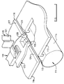
- the modified apparatus of Figure 3 is intended to implant tufts of a row sequentially The tufts may be implanted one at a time.
- the apparatus may be adapted to implant several tufts of a row concurrently at respective positions which are spaced apart by distances considerably greater than the pitch of tufts along the row.
- Figure 3 means for implanting a single tuft.
- the arrangement may be duplicated for implanting two tufts at a time.
- the modified apparatus of Figure 3 includes a dividing member 125 which divides the slot 118 transversely of its length into three portions arranged in succession along the length of the slot. These are first end portion 126, a second end portion 127 and an intermediate portion 128 which lies between the end portions. The dimensions of the intermediate portion 128 are fixed.
- the dividing member is movable along the slot to vary the lengths of the end portions 126 and 127.
- the presser member 120 of the apparatus shown in Figure 3 has dimensions such that it can be received with clearance in the intermediate portion 128 of the slot.
- the presser member can be moved along the slot to maintain alignment of the presser member with the intermediate portion of the slot. That dimension of the intermediate portion which extends along the slot is short, relative to the overall length of the slot and preferably does not exceed twice the width of the slot.
- the width of the slot is typically no more than 2% of the length of the slot.
- each of the upstream and downstream faces of the presser member 120 There is farmed in each of the upstream and downstream faces of the presser member 120 a single yarn-receiving groove. These grooves are mutually aligned in the direction of movement of the web through the attaching station.
- the means for delivering tuft-forming lengths of yarn to the attaching station of the modified apparatus shown in Figure 3 may be the same as the delivering means used in the apparatus of Figures 1 and 2. However, since yarn lengths are required to be moved individually to the attaching station, a gripper 119 which has a relatively short dimension extending in a direction along the slot 118 may be used. This dimension of the gripper is preferably several times the thickness of on uncompressed length of yarn, so that there is no significant risk of the gripper failing to grip the length securely.
- a source of yarn which includes only a single yarn length of each colour to be used in the manufacture of the pile fabric. Relative movement of the gripper and yarn source are then used to select yarn of appropriate colour for each length which is to be attached to the web.
- the dividing member 125 preferably has opposite wall portions 129 and 130 which depend into the slot 118 at opposite ends of the intermediate portion of the slot.
- One of these wall portions can be used to control the attitude of the last-implanted tuft during implanting of an adjacent tuft of the row.
- the dividing member 125 is moved along the slot 118 sufficiently for to ensure that the newly implanted tuft escapes from the intermediate portion 128 of the slot into one or other of the end portions 126 and 127.
- the dividing member is then returned along the slot towards the newly implanted tuft to the position where an adjacent tuft is to be implanted.
- the presser member 120 and the gripper 119 follow this movement of the dividing member 125.
- Pneumatic piston and cylinder units may be used for moving the dividing member, the presser member and the gripper in directions along the slot.
- Known transducers may be used to provide electrical signals representing movement of or the positions of these components of the apparatus and the apparatus may include an electronic controller for controlling the piston and cylinder units and other components of the drive means.
Landscapes
- Engineering & Computer Science (AREA)
- Textile Engineering (AREA)
- Chemical & Material Sciences (AREA)
- Materials Engineering (AREA)
- Treatment Of Fiber Materials (AREA)
- Woven Fabrics (AREA)
- Knitting Of Fabric (AREA)
- Yarns And Mechanical Finishing Of Yarns Or Ropes (AREA)
- Laminated Bodies (AREA)
- Manufacturing Of Multi-Layer Textile Fabrics (AREA)
Claims (11)
- Vorrichtung geeignet zur Benutzung in der Herstellung eines Faserwerkstoffes durch Anbringen von florbildenden Garnabschnitten auf ein vorgeformtes Gewebe, wobei die Vorrichtung Führungsmittel zur Führung des Gewebes entlang eines Pfades durch eine Anbringungsstation besitzt, Flor-Steuermittel (16, 17, 116, 117), die an der Anbringungsstation einen Schlitz (18, 118) bilden, wobei der Schlitz mit seiner Länge quer zur Länge des Pfades an der Anbringungsstation angeordnet ist, und Pressmittel (20, 120) zum Pressen des Garns durch den Schlitz auf das Gewebe an der Anbringungsstation,
dadurch gekennzeichnet, daß
wenigstens eines der Pressmittel (20, 120) und der Flor-Steuermittel (16, 17, 116, 117) eine garnaufnehmende Kerbe (21, 121) besitzt, wobei die Länge der Kerbe quer sowohl zur Erstreckung des Pfades an der Anbringungsstation und der Erstreckung des Schlitzes (18, 118) verläuft. - Vorrichtung nach Anspruch 1, dadurch gekennzeichnet, daß zwei garnaufnehmende Kerben (21, 121) zur Aufnahme entsprechender Glieder eines einzelnen, im wesentlichen U-förmigen Doppel-Flors vorgesehen sind.
- Vorrichtung nach Anspruch 1 oder Anspruch 2, wobei die oder jede garnaufnehmende Kerbe (21, 121) in den Andrückmitteln (20, 120) gebildet ist.
- Vorrichtung nach Anspruch 3, dadurch gekennzeichnet, daß florsteuernde Mittel (16, 17, 116, 117) flache, einander gegenüberliegende Grenzen des Schlitzes (18, 118) bilden.
- Vorrichtung nach Anspruch 1 oder Anspruch 2, die geeignet zur Aufbringung einer Reihe von Floren gemeinsam auf das Gewebe, und wobei entweder eine Einzelgarn aufnehmende Kerbe (21) oder ein Paar von garnaufnehmenden Kerben für jeden Flor der Reihe vorgesehen sind.
- Vorrichtung nach einem der Ansprüche 1 bis 4, wobei die florsteuernden Mittel ein Teiler-Element (125) umfassen, das den Schlitz (118) quer zu seiner Länge in Abschnitte teilt, die aufeinanderfolgend entlang des Schlitzes angeordnet sind, wobei die Andrückmittel (120) örtlich zugeordnet sind, um nur in einen der Abschnitte zur Zeit einzutreten.
- Vorrichtung nach Anspruch 6, wobei das Teiler-Element (125) entlang des Schlitzes beweglich ist.
- Vorrichtung nach Anspruch 6, wobei das Teiler-Element (125) dazu vorgesehen ist, den Schlitz in einen Zwischenabschnitt und zwei Endabschnitte zu teilen und wobei die Pressmittel (120) derart angeordnet sind, nur in den Zwischenabschnitt einzutreten.
- Vorrichtung nach Anspruch 8, wobei der Zwischenabschnitt eine Länge nicht größer als das Doppelte der Breite des Schlitzes (118) aufweist.
- Verfahren zur Herstellung eines Velour-Teppichs, wobei ein Gewebe (10) durch eine Anbringungsstation bewegt wird und die florbildende Garnlänge auf dem Gewebe an der Anbringungsstation angebracht wird, wobei das Verhalten und die Position der Längen relativ zum Gewebe während der Anbringung der Längen auf dem Gewebe durch florsteuernde Mittel (16, 17, 20) an der Anbringungsstation gesteuert ist, dadurch gekennzeichnet, daß eine garnaufnehmende Kerbe (21) in den florsteuernden Mitteln vorgesehen ist und daß eine florbildende Garnlänge in die Kerbe bewegt wird, während sie immer noch von dem Gewebe beabstandet ist und in der Kerbe verbleibt, während sie auf das Gewebe zubewegt wird.
- Verfahren nach Anspruch 10, wobei jede florbildende Länge des Garns in eine U-Form gebogen wird und einen Doppel-Flor bildet, ein Paar von garnaufnehmenden Kerben (21) in den Flor-Steuermitteln gebildet werden und Glieder des Doppel-Flors in jeweils zugeordnete des Paars an Kerben bewegt werden.
Applications Claiming Priority (2)
| Application Number | Priority Date | Filing Date | Title |
|---|---|---|---|
| GB8913956A GB2233675B (en) | 1989-06-16 | 1989-06-16 | Apparatus and method for the manufacture of a pile fabric |
| GB8913956 | 1989-06-16 |
Publications (2)
| Publication Number | Publication Date |
|---|---|
| EP0402664A1 EP0402664A1 (de) | 1990-12-19 |
| EP0402664B1 true EP0402664B1 (de) | 1994-07-13 |
Family
ID=10658607
Family Applications (1)
| Application Number | Title | Priority Date | Filing Date |
|---|---|---|---|
| EP90109659A Expired - Lifetime EP0402664B1 (de) | 1989-06-16 | 1990-05-21 | Verfahren und Vorrichtung zur Herstellung eines Florgewebes |
Country Status (7)
| Country | Link |
|---|---|
| US (1) | US5135602A (de) |
| EP (1) | EP0402664B1 (de) |
| JP (1) | JPH03119167A (de) |
| AT (1) | ATE108497T1 (de) |
| AU (1) | AU622741B2 (de) |
| DE (1) | DE69010582D1 (de) |
| GB (1) | GB2233675B (de) |
Families Citing this family (3)
| Publication number | Priority date | Publication date | Assignee | Title |
|---|---|---|---|---|
| US5443881A (en) * | 1989-12-27 | 1995-08-22 | Milliken Research Corporation | Heat stabilized pile fabric |
| EP1762807B2 (de) | 2005-09-07 | 2016-12-28 | Modine Manufacturing Company | Wärmetauscher |
| BE1020203A5 (nl) | 2011-08-26 | 2013-06-04 | Cttec Bvba | Werkwijze voor het vervaardigen van pooltapijt. |
Family Cites Families (8)
| Publication number | Priority date | Publication date | Assignee | Title |
|---|---|---|---|---|
| BE510730A (de) * | 1952-04-07 | |||
| GB1422524A (en) * | 1972-01-21 | 1976-01-28 | Bond Worth Ltd | Pile fabrics and methods and apparatus for the production thereof |
| US3878011A (en) * | 1973-01-05 | 1975-04-15 | Bond Worth Ltd | Pile fabrics and methods and apparatus for the production thereof |
| GB1421061A (en) * | 1973-01-05 | 1976-01-14 | Bond Worth Ltd | Apparatus for the production of pile fabrics |
| GB1599764A (en) * | 1977-04-15 | 1981-10-07 | Bond Worth Ltd | Methods of and apparatus for manufacturing pile fabrics |
| GB1549694A (en) * | 1976-04-14 | 1979-08-08 | Bonded Carpets Ltd | Pile fabric manufacturing method and apparatus |
| US4549496A (en) * | 1984-03-16 | 1985-10-29 | Fabrication Center, Inc. | Apparatus and method for producing patterned tufted goods |
| GB2225351B (en) * | 1988-11-10 | 1992-05-06 | Carpets Of Worth Limited | Method of and apparatus for manufacturing pile fabrics |
-
1989
- 1989-06-16 GB GB8913956A patent/GB2233675B/en not_active Expired - Lifetime
- 1989-12-13 AU AU46193/89A patent/AU622741B2/en not_active Ceased
-
1990
- 1990-05-21 EP EP90109659A patent/EP0402664B1/de not_active Expired - Lifetime
- 1990-05-21 DE DE69010582T patent/DE69010582D1/de not_active Expired - Lifetime
- 1990-05-21 AT AT90109659T patent/ATE108497T1/de not_active IP Right Cessation
- 1990-06-11 US US07/535,730 patent/US5135602A/en not_active Expired - Fee Related
- 1990-06-16 JP JP2158539A patent/JPH03119167A/ja active Pending
Also Published As
| Publication number | Publication date |
|---|---|
| US5135602A (en) | 1992-08-04 |
| DE69010582D1 (de) | 1994-08-18 |
| GB2233675B (en) | 1992-09-16 |
| GB2233675A (en) | 1991-01-16 |
| AU4619389A (en) | 1990-12-20 |
| JPH03119167A (ja) | 1991-05-21 |
| AU622741B2 (en) | 1992-04-16 |
| GB8913956D0 (en) | 1989-08-02 |
| EP0402664A1 (de) | 1990-12-19 |
| ATE108497T1 (de) | 1994-07-15 |
Similar Documents
| Publication | Publication Date | Title |
|---|---|---|
| CA1119053A (en) | Method, means and tufted product | |
| US4991523A (en) | Tufting apparatus | |
| EP0047106B1 (de) | Verfahren und Vorrichtung zum Anbringen von elastischen Bändern zwischen zwei, im wesentlichen nicht elastischen, gegenüberliegenden Bahnen | |
| US4317419A (en) | Method, means, and tufted product | |
| DE1785717B2 (de) | Verfahren und Vorrichtung zur Herstellung nichtgewebter Florstoffe | |
| JP6886461B2 (ja) | シャーシウェブにタブを貼り付けるためのユニット | |
| US5370024A (en) | Apparatus for the manufacture of sheets bearing display samples | |
| CN87107288A (zh) | 用纵向衬纬器和横向栅状板进行经编机纬纱喂入的工艺和设备 | |
| US5135602A (en) | Apparatus for the manufacture of a pile fabric | |
| US5211208A (en) | Double-point welding machine | |
| HUT70607A (en) | Method of and apparatus for reducing the thickness of regions of sheet material workpieces | |
| IE51767B1 (en) | Reinforced structures | |
| US3878011A (en) | Pile fabrics and methods and apparatus for the production thereof | |
| US3847691A (en) | Pile fabrics and methods and apparatus for the production thereof | |
| US5081752A (en) | Installation for producing flat textile bodies | |
| EP0456863A1 (de) | Verfahren und Vorrichtung zur Herstellung einer Florbahn | |
| GB2035444A (en) | Method and apparatus for finishing a pair of elongate slide fastener stringers | |
| US2593585A (en) | Web feeding means for cutting machines | |
| US7044172B2 (en) | Apparatus and method for supplying tufts of yarn | |
| US4902375A (en) | Apparatus for assembling a continuous stream of composite labels | |
| GB2085494A (en) | Reinforced structures | |
| US4201608A (en) | Methods of and apparatus for manufacturing pile fabrics | |
| GB2234532A (en) | Pile fabrics | |
| US3944451A (en) | Method of and apparatus for making a plush-type cloth | |
| GB2261886A (en) | Apparatus for use in manufacturing a pile fabric |
Legal Events
| Date | Code | Title | Description |
|---|---|---|---|
| PUAI | Public reference made under article 153(3) epc to a published international application that has entered the european phase |
Free format text: ORIGINAL CODE: 0009012 |
|
| AK | Designated contracting states |
Kind code of ref document: A1 Designated state(s): AT BE CH DE DK ES FR GB GR IT LI LU NL SE |
|
| 17P | Request for examination filed |
Effective date: 19901029 |
|
| 17Q | First examination report despatched |
Effective date: 19920918 |
|
| GRAA | (expected) grant |
Free format text: ORIGINAL CODE: 0009210 |
|
| AK | Designated contracting states |
Kind code of ref document: B1 Designated state(s): AT BE CH DE DK ES FR GB GR IT LI LU NL SE |
|
| PG25 | Lapsed in a contracting state [announced via postgrant information from national office to epo] |
Ref country code: IT Free format text: LAPSE BECAUSE OF FAILURE TO SUBMIT A TRANSLATION OF THE DESCRIPTION OR TO PAY THE FEE WITHIN THE PRESCRIBED TIME-LIMIT;WARNING: LAPSES OF ITALIAN PATENTS WITH EFFECTIVE DATE BEFORE 2007 MAY HAVE OCCURRED AT ANY TIME BEFORE 2007. THE CORRECT EFFECTIVE DATE MAY BE DIFFERENT FROM THE ONE RECORDED. Effective date: 19940713 Ref country code: FR Effective date: 19940713 Ref country code: AT Effective date: 19940713 Ref country code: NL Effective date: 19940713 Ref country code: GR Free format text: LAPSE BECAUSE OF FAILURE TO SUBMIT A TRANSLATION OF THE DESCRIPTION OR TO PAY THE FEE WITHIN THE PRESCRIBED TIME-LIMIT Effective date: 19940713 Ref country code: CH Effective date: 19940713 Ref country code: LI Effective date: 19940713 Ref country code: DK Effective date: 19940713 Ref country code: ES Free format text: THE PATENT HAS BEEN ANNULLED BY A DECISION OF A NATIONAL AUTHORITY Effective date: 19940713 |
|
| REF | Corresponds to: |
Ref document number: 108497 Country of ref document: AT Date of ref document: 19940715 Kind code of ref document: T |
|
| REF | Corresponds to: |
Ref document number: 69010582 Country of ref document: DE Date of ref document: 19940818 |
|
| PG25 | Lapsed in a contracting state [announced via postgrant information from national office to epo] |
Ref country code: SE Effective date: 19941013 |
|
| PG25 | Lapsed in a contracting state [announced via postgrant information from national office to epo] |
Ref country code: DE Effective date: 19941014 |
|
| REG | Reference to a national code |
Ref country code: CH Ref legal event code: PL |
|
| EN | Fr: translation not filed | ||
| NLV1 | Nl: lapsed or annulled due to failure to fulfill the requirements of art. 29p and 29m of the patents act | ||
| PLBE | No opposition filed within time limit |
Free format text: ORIGINAL CODE: 0009261 |
|
| STAA | Information on the status of an ep patent application or granted ep patent |
Free format text: STATUS: NO OPPOSITION FILED WITHIN TIME LIMIT |
|
| PG25 | Lapsed in a contracting state [announced via postgrant information from national office to epo] |
Ref country code: LU Free format text: LAPSE BECAUSE OF NON-PAYMENT OF DUE FEES Effective date: 19950531 |
|
| 26N | No opposition filed | ||
| REG | Reference to a national code |
Ref country code: GB Ref legal event code: IF02 |
|
| PGFP | Annual fee paid to national office [announced via postgrant information from national office to epo] |
Ref country code: GB Payment date: 20030519 Year of fee payment: 14 |
|
| PGFP | Annual fee paid to national office [announced via postgrant information from national office to epo] |
Ref country code: BE Payment date: 20030725 Year of fee payment: 14 |
|
| PG25 | Lapsed in a contracting state [announced via postgrant information from national office to epo] |
Ref country code: GB Free format text: LAPSE BECAUSE OF NON-PAYMENT OF DUE FEES Effective date: 20040521 |
|
| PG25 | Lapsed in a contracting state [announced via postgrant information from national office to epo] |
Ref country code: BE Free format text: LAPSE BECAUSE OF NON-PAYMENT OF DUE FEES Effective date: 20040531 |
|
| BERE | Be: lapsed |
Owner name: *BONDAX CARPETS LTD Effective date: 20040531 |
|
| GBPC | Gb: european patent ceased through non-payment of renewal fee |
Effective date: 20040521 |