EP0402692A2 - Procédé et dispositif pour le contrôle de la transmission de chaleur d'agents refroidisseurs liquides en coulée continue - Google Patents
Procédé et dispositif pour le contrôle de la transmission de chaleur d'agents refroidisseurs liquides en coulée continue Download PDFInfo
- Publication number
- EP0402692A2 EP0402692A2 EP90110124A EP90110124A EP0402692A2 EP 0402692 A2 EP0402692 A2 EP 0402692A2 EP 90110124 A EP90110124 A EP 90110124A EP 90110124 A EP90110124 A EP 90110124A EP 0402692 A2 EP0402692 A2 EP 0402692A2
- Authority
- EP
- European Patent Office
- Prior art keywords
- liquid
- gas
- bubbles
- ingot
- droplets
- Prior art date
- Legal status (The legal status is an assumption and is not a legal conclusion. Google has not performed a legal analysis and makes no representation as to the accuracy of the status listed.)
- Withdrawn
Links
- 239000007788 liquid Substances 0.000 title claims abstract description 130
- 239000002826 coolant Substances 0.000 title claims abstract description 110
- 238000000034 method Methods 0.000 title claims abstract description 72
- 238000009749 continuous casting Methods 0.000 title description 8
- 238000012544 monitoring process Methods 0.000 claims abstract description 11
- 238000005266 casting Methods 0.000 claims description 62
- 229910052751 metal Inorganic materials 0.000 claims description 34
- 239000002184 metal Substances 0.000 claims description 34
- 239000000203 mixture Substances 0.000 claims description 14
- 238000007711 solidification Methods 0.000 claims description 12
- 230000008023 solidification Effects 0.000 claims description 12
- 238000000605 extraction Methods 0.000 claims description 10
- 230000000694 effects Effects 0.000 claims description 9
- 238000002156 mixing Methods 0.000 claims description 9
- 230000036961 partial effect Effects 0.000 claims description 9
- 230000003247 decreasing effect Effects 0.000 claims description 4
- 239000000155 melt Substances 0.000 claims description 3
- 238000012216 screening Methods 0.000 claims 1
- 238000001816 cooling Methods 0.000 abstract description 24
- 239000007789 gas Substances 0.000 description 108
- XLYOFNOQVPJJNP-UHFFFAOYSA-N water Substances O XLYOFNOQVPJJNP-UHFFFAOYSA-N 0.000 description 58
- CURLTUGMZLYLDI-UHFFFAOYSA-N Carbon dioxide Chemical compound O=C=O CURLTUGMZLYLDI-UHFFFAOYSA-N 0.000 description 46
- 230000008569 process Effects 0.000 description 24
- 239000001569 carbon dioxide Substances 0.000 description 23
- 229910002092 carbon dioxide Inorganic materials 0.000 description 23
- 229910045601 alloy Inorganic materials 0.000 description 9
- 239000000956 alloy Substances 0.000 description 9
- 238000009413 insulation Methods 0.000 description 9
- 239000012530 fluid Substances 0.000 description 8
- 239000000498 cooling water Substances 0.000 description 7
- 230000008859 change Effects 0.000 description 6
- 229910052782 aluminium Inorganic materials 0.000 description 5
- XAGFODPZIPBFFR-UHFFFAOYSA-N aluminium Chemical compound [Al] XAGFODPZIPBFFR-UHFFFAOYSA-N 0.000 description 5
- 230000007423 decrease Effects 0.000 description 5
- 238000009835 boiling Methods 0.000 description 4
- 238000006243 chemical reaction Methods 0.000 description 4
- 230000001419 dependent effect Effects 0.000 description 4
- 239000002245 particle Substances 0.000 description 4
- 230000035945 sensitivity Effects 0.000 description 4
- 239000007787 solid Substances 0.000 description 4
- 239000000126 substance Substances 0.000 description 4
- RYGMFSIKBFXOCR-UHFFFAOYSA-N Copper Chemical compound [Cu] RYGMFSIKBFXOCR-UHFFFAOYSA-N 0.000 description 3
- 239000003570 air Substances 0.000 description 3
- 230000015572 biosynthetic process Effects 0.000 description 3
- 229910052802 copper Inorganic materials 0.000 description 3
- 239000010949 copper Substances 0.000 description 3
- 150000002739 metals Chemical class 0.000 description 3
- 230000002829 reductive effect Effects 0.000 description 3
- 230000000979 retarding effect Effects 0.000 description 3
- IJGRMHOSHXDMSA-UHFFFAOYSA-N Atomic nitrogen Chemical compound N#N IJGRMHOSHXDMSA-UHFFFAOYSA-N 0.000 description 2
- XEEYBQQBJWHFJM-UHFFFAOYSA-N Iron Chemical compound [Fe] XEEYBQQBJWHFJM-UHFFFAOYSA-N 0.000 description 2
- PXHVJJICTQNCMI-UHFFFAOYSA-N Nickel Chemical compound [Ni] PXHVJJICTQNCMI-UHFFFAOYSA-N 0.000 description 2
- 238000000149 argon plasma sintering Methods 0.000 description 2
- 238000010586 diagram Methods 0.000 description 2
- 239000000835 fiber Substances 0.000 description 2
- 238000004519 manufacturing process Methods 0.000 description 2
- 239000000463 material Substances 0.000 description 2
- 230000005499 meniscus Effects 0.000 description 2
- 239000012071 phase Substances 0.000 description 2
- 230000009467 reduction Effects 0.000 description 2
- 238000005096 rolling process Methods 0.000 description 2
- 229910001148 Al-Li alloy Inorganic materials 0.000 description 1
- 229910000906 Bronze Inorganic materials 0.000 description 1
- FYYHWMGAXLPEAU-UHFFFAOYSA-N Magnesium Chemical compound [Mg] FYYHWMGAXLPEAU-UHFFFAOYSA-N 0.000 description 1
- HCHKCACWOHOZIP-UHFFFAOYSA-N Zinc Chemical compound [Zn] HCHKCACWOHOZIP-UHFFFAOYSA-N 0.000 description 1
- QCWXUUIWCKQGHC-UHFFFAOYSA-N Zirconium Chemical compound [Zr] QCWXUUIWCKQGHC-UHFFFAOYSA-N 0.000 description 1
- JFBZPFYRPYOZCQ-UHFFFAOYSA-N [Li].[Al] Chemical compound [Li].[Al] JFBZPFYRPYOZCQ-UHFFFAOYSA-N 0.000 description 1
- 238000010521 absorption reaction Methods 0.000 description 1
- 239000000654 additive Substances 0.000 description 1
- QVGXLLKOCUKJST-UHFFFAOYSA-N atomic oxygen Chemical compound [O] QVGXLLKOCUKJST-UHFFFAOYSA-N 0.000 description 1
- 239000010974 bronze Substances 0.000 description 1
- 239000000919 ceramic Substances 0.000 description 1
- 229910017052 cobalt Inorganic materials 0.000 description 1
- 239000010941 cobalt Substances 0.000 description 1
- GUTLYIVDDKVIGB-UHFFFAOYSA-N cobalt atom Chemical compound [Co] GUTLYIVDDKVIGB-UHFFFAOYSA-N 0.000 description 1
- KUNSUQLRTQLHQQ-UHFFFAOYSA-N copper tin Chemical compound [Cu].[Sn] KUNSUQLRTQLHQQ-UHFFFAOYSA-N 0.000 description 1
- 238000005336 cracking Methods 0.000 description 1
- 238000007599 discharging Methods 0.000 description 1
- 238000009826 distribution Methods 0.000 description 1
- 239000011521 glass Substances 0.000 description 1
- 238000002347 injection Methods 0.000 description 1
- 239000007924 injection Substances 0.000 description 1
- 229910052742 iron Inorganic materials 0.000 description 1
- 238000012538 light obscuration Methods 0.000 description 1
- 239000001989 lithium alloy Substances 0.000 description 1
- 239000011777 magnesium Substances 0.000 description 1
- 229910052749 magnesium Inorganic materials 0.000 description 1
- 238000002844 melting Methods 0.000 description 1
- 230000008018 melting Effects 0.000 description 1
- 229910052759 nickel Inorganic materials 0.000 description 1
- 229910052757 nitrogen Inorganic materials 0.000 description 1
- 230000009965 odorless effect Effects 0.000 description 1
- 239000001301 oxygen Substances 0.000 description 1
- 229910052760 oxygen Inorganic materials 0.000 description 1
- 230000000750 progressive effect Effects 0.000 description 1
- 230000001737 promoting effect Effects 0.000 description 1
- 238000007712 rapid solidification Methods 0.000 description 1
- 239000000523 sample Substances 0.000 description 1
- 239000007790 solid phase Substances 0.000 description 1
- 239000000243 solution Substances 0.000 description 1
- 230000003068 static effect Effects 0.000 description 1
- 239000008400 supply water Substances 0.000 description 1
- 230000007704 transition Effects 0.000 description 1
- 229910052725 zinc Inorganic materials 0.000 description 1
- 239000011701 zinc Substances 0.000 description 1
- 229910052726 zirconium Inorganic materials 0.000 description 1
Images

Classifications
-
- B—PERFORMING OPERATIONS; TRANSPORTING
- B22—CASTING; POWDER METALLURGY
- B22D—CASTING OF METALS; CASTING OF OTHER SUBSTANCES BY THE SAME PROCESSES OR DEVICES
- B22D11/00—Continuous casting of metals, i.e. casting in indefinite lengths
- B22D11/16—Controlling or regulating processes or operations
- B22D11/22—Controlling or regulating processes or operations for cooling cast stock or mould
-
- Y—GENERAL TAGGING OF NEW TECHNOLOGICAL DEVELOPMENTS; GENERAL TAGGING OF CROSS-SECTIONAL TECHNOLOGIES SPANNING OVER SEVERAL SECTIONS OF THE IPC; TECHNICAL SUBJECTS COVERED BY FORMER USPC CROSS-REFERENCE ART COLLECTIONS [XRACs] AND DIGESTS
- Y10—TECHNICAL SUBJECTS COVERED BY FORMER USPC
- Y10T—TECHNICAL SUBJECTS COVERED BY FORMER US CLASSIFICATION
- Y10T137/00—Fluid handling
- Y10T137/2496—Self-proportioning or correlating systems
- Y10T137/2499—Mixture condition maintaining or sensing
-
- Y—GENERAL TAGGING OF NEW TECHNOLOGICAL DEVELOPMENTS; GENERAL TAGGING OF CROSS-SECTIONAL TECHNOLOGIES SPANNING OVER SEVERAL SECTIONS OF THE IPC; TECHNICAL SUBJECTS COVERED BY FORMER USPC CROSS-REFERENCE ART COLLECTIONS [XRACs] AND DIGESTS
- Y10—TECHNICAL SUBJECTS COVERED BY FORMER USPC
- Y10T—TECHNICAL SUBJECTS COVERED BY FORMER US CLASSIFICATION
- Y10T137/00—Fluid handling
- Y10T137/2496—Self-proportioning or correlating systems
- Y10T137/2499—Mixture condition maintaining or sensing
- Y10T137/2509—By optical or chemical property
Definitions
- the present invention relates to methods and apparatus for controlling the heat transfer characteristics of a liquid coolant containing gas bubbles. More particularly, the method and apparatus of the present invention relate to monitoring and retarding the withdrawal of heat from the surface of a continuously cast ingot by means of a liguid coolant containing gas bubbles.
- the casting mold is relatively short in the axial direction and is hollow or otherwise adapted to receive a liquid cooling medium, such as water, which chills and solidifies the ingot meniscus. The water is then discharged from the mold and continues to chill the ingot as it contacts the ingot surface.
- Molds are preferably constructed of aluminum but may also be copper, bronze or another material which exhibits high thermal conductivity.
- U.S. Patent No. 4,166,495 issued to Yu discloses an ingot casting method for controlling the withdrawal of heat from the surface of a cooling ingot.
- the essence of the invention of U.S. Patent 4,166,495 is the mixing of a gas with the liquid coolant before the liquid coolant is applied to the ingot surface.
- the gas mixed in the liquid coolant acts to retard the rate of heat extraction of the liquid coolant.
- the rate of heat extraction by the mold is increased. The increased rate of heat extraction is used on subsequent portions of the emerging ingot length.
- U.S. Patent No. 4,166,495 is a commercially successful method of retarding the cooling effect of the liquid coolant and has come to be known in the aluminum industry as the Alcoa 729 process.
- the Alcoa 729 process has been successfully used to cast ingot having a width to thickness ratio of 5.3.
- a preferred coolant of the Alcoa 729 process is water and one preferred gas is CO2.
- Water is a preferred coolant because it is inexpensive and abundant.
- CO2 is preferred because it is odorless, inexpensive, highly soluble in water and relatively harmless to the environment.
- CO2 does not suffer from many of the disadvantages associated with chemical additives.
- gases which are substantially insoluble in water such as for example air, may also be used in practicing the method of U.S. Patent No. 4,166,495.
- U.S. Patent No. 4,693,298 issued to Wagstaff discloses a means and technique for casting metals at a controlled direct cooling rate.
- the method of U.S. Patent No. 4,693,298 involves mixing liquid coolant and a gas which is substantially insoluble in the liquid coolant by discharging the gas through jets. The jets release the gas in the flowing liquid coolant as a mass of bubbles that tend to remain discrete and undissolved in the coolant as the coolant on the surface of the ingot.
- the Alcoa 729 process is economical and effective, it is improvable.
- the amount of gas that must be mixed with the liquid coolant in the process is very sensitive to changes in temperature, mixing pressure, and water quality.
- the ability of the gas to retard the heat of extraction of the liquid coolant is determined by the volatility of the liquid, which depends on the concentration of gas mixed in the liquid coolant, the temperature of the liquid coolant, the velocity of coolant flow and the coolant quality of the liquid coolant.
- quality as used herein means the chemistry of the liquid coolant and it includes properties such as ph, alkalinity, dissolved and suspended solids, surface tension and ionic species.
- the sensitivity of the process to changes in temperature and coolant quality requires that the amount of gas that is added to the cooling medium must be constantly adjusted by trial and error so that the desired heat transfer characteristics of the liquid coolant can be maintained.
- the temperature sensitivity and coolant quality sensitivity of the Alcoa 729 process makes casting of some ingots extremely difficult.
- a method for continuously controlling the heat exchange capacity of a liquid gas mixture which is a liquid containing gas bubbles or a gas containing droplets of liquid, said method comprising the steps of: detecting the relative density of said bubbles or droplets; comparing said relative density to a reference density range; and varying the amount of gas in said liquid so that said relative density is within said reference range.
- a method for continuously monitoring the heat exchange capacity of a liquid-gas mixture comprising the steps of: generating a signal which is related to the number density of said bubbles or droplets; and comparing said generated signal to a reference signal.
- a control apparatus for continuously controlling the heat exchange capacity of a liquid containing gas bubbles or a gas containing liquid droplets, said apparatus comprising: detecting means for detecting the relative density of said bubbles or droplets; and a varying means for varying the amount of gas dissolved within said liquid coolant if said number density is outside a reference range.
- an apparatus for comparing the heat exchange capacity of a liquid-gas mixture comprising: a generating means for generating a signal related to the relative density of said bubbles or droplets; and a comparing means for comparing said generated signal to a reference signal.
- a casting apparatus for casting a melt into an ingot, said apparatus comprising: an open-ended mold for casting an ingot; an application means for applying liquid-gas mixture to said ingot to effect at least partial solidification thereof, said liquid containing a gas bubbles or said gas containing liquid droplets which retard the rate of heat extraction from said ingot; a detecting means for detecting the density of said bubbles or droplets to infer the heat transfer characteristics of said liquid coolant; a varying means for varying the amount of gas dissolved within said liquid coolant if said inferred heat transfer characteristic is outside a reference range; and a means for applying said liquid coolant to said ingot emerging from said mold to effect at least partial solidification of the molten metal.
- a method for continuously monitoring the cooling capacity of a liquid coolant containing gas bubbles comprising the steps of: (a) sensing the number density of bubbles within a predetermined size range and (b) comparing the number density to a predetermined number and if necessary varying the amount of gas that is being mixed with the liquid coolant so that the number density obtained is within said predetermined range.
- a second aspect of the invention is an improved method for continuously casting metal ingots which includes the steps of: (a casting molten metal into an open-ended mold; (b) providing a liquid coolant; (c) mixing a gas with the liquid coolant so that the liquid coolant contains gas bubbles; (d) measuring the size and number density of the bubbles of the gas in the liquid coolant by use of a sensor means to infer a heat transfer characteristic of the liquid coolant; (e) varying the amount of gas that is being mixed with the liquid coolant so that the inferred heat transfer characteristic is within a predetermined range; and (f) applying the liquid coolant to the casting operation.
- Another aspect of the invention is a method for continuously monitoring the cooling capacity of a liquid coolant containing gas bubbles, said method comprising the steps of: (a) generating a signal which is related to the number density of the bubbles within the liquid coolant and (b) comparing the generated signal to a predetermined signal range and if necessary varying the amount of gas that is being mixed with the liquid coolant so that the generated signal is within the predetermined signal range.
- Another aspect of the present invention is an apparatus for continuously monitoring the cooling capacity of a liquid coolant containing gas bubbles, the apparatus includes: (a) a measuring means for measuring the number density of the bubbles to infer the heat transfer characteristics of the liquid coolant; and (b) a control means for varying the amount of gas in the liquid coolant so that the number density is within a predetermined range.
- Still another aspect of the present invention is an apparatus for casting a melt into an ingot: (a) a mold for holding a reservoir of melt; (b) an application means for applying liquid cooling medium to the mold to effectuate at least partial solidification of the molten metal therein, the liquid cooling medium containing a gas which forms bubbles which act to retard the rate of heat extraction from the ingot; (c) a sensing means for sensing the number density of bubbles within a predetermined size range and (d) a means for comparing the number density to a predetermined number and if necessary varying the amount of gas that is being mixed with the liquid coolant so that the number density obtained is within said predetermined range; and (e) a control means for varying the amount of gas mixed with the liquid cooling medium to bring the number density the liquid cooling medium within a predetermined range.
- An additional aspect of the present invention is a method for continuously casting metal ingots having a higher width to thickness ratio than existing methods, the method comprises the steps of: (a) casting molten metal into an open-ended mold having a high width to thickness ratio; (b) applying liquid cooling medium to the mold to effectuate at least partial solidification of the molten metal therein, the liquid cooling medium containing a gas which forms bubbles in the liquid cooling medium, the bubbles act to retard the rate of heat extraction from said ingot; (c) monitoring the size and number density of the bubbles by use of a light source to infer heat transfer characteristics of the liquid cooling medium; (d) inferring a heat transfer characteristics of the liquid cooling medium from the size and number density of the bubbles; and (e) varying the amount of gas mixed with the liquid cooling medium to bring the inferred heat transfer characteristic of the liquid cooling medium within a predetermined range.
- Another aspect of the present invention is a method for continuously casting metal ingots using a liquid coolant, the method comprising the steps of: (a) casting molten metal into an open-ended mold used to form an ingot which emerges there from; (b) providing a liquid coolant; (c) mixing a gas with the liquid coolant so that the liquid coolant contains gas bubbles; (d) passing light through the liquid coolant onto a light sensing device; (e) sensing the number density of micron size bubbles from the scattering of the light; (f) comparing the number density to a predetermined number and if necessary reducing the amount of said gas that is being mixed with the liquid if the number density exceeds said predetermined range and increasing the amount of the gas that is being mixed with the liquid if the number density falls below the predetermined range, the predetermined range varying from a first range that is used during the initial stages of casting when the ingot is in a startup state to a second range that is used when the emerging ingot is in a steady state; and (g)
- continuous refers to the progressive and uninterrupted formation of a cast metal ingot in a mold which is open at both ends.
- the pouring operation may continue indefinitely if the cast ingot is cut into sections of suitable length at a location away from the mold. Alternatively, the pouring operation may be started and stopped in the manufacture of each ingot. The latter process is commonly referred to as semicontinuous casting and is intended to be comprehended by the term "continuous”.
- the prior art apparatus shown in Figure 1 generally includes a pouring spout 10 for molten metal 12, a casting mold 14 generally defining the transverse dimensions of the ingot 16 being cast.
- the casting mold may be any type of casting mold which is known in the art, including a mold used for electromagnetic casting.
- the prior art apparatus of Fig. 1 also includes a vertically movable bottom block 18 which closes the lower end of the mold 14 at the beginning of the casting operation and by its descent determines the rate at which the ingot 16 is advanced from the mold 14.
- Metal "head” is defined as distance from the free surface of the molten metal in the casting basin to the bottom of mold 14. Head is illustrated in Fig. 1 by dimension “h”. "Crater” is the term used to define the molten metal pool which exhibits an inverted, generally wedge-shaped configuration from the meniscus of the molten metal level in mold 14 to a location some distance from the exit end of mold 14, which is centrally located in ingot 16.
- cross-sectional crater profile is often illustrated as a solid line separating molten metal from solid metal, it will be understood by those skilled in the art that there is a mushy zone 22 where the metal is not fully solid yet not really liquid separating the molten and solid phases.
- molten metal 12 may be transferred to the casting unit directly from a furnace or from a melting crucible.
- Molten metal 12 is poured through pouring spout 10 or the like into mold 14 having its bottom closed by bottom block 18.
- Flow control devices may be provided to minimize cascading and turbulent metal flow and to insure even molten metal distribution.
- Mold 14 is a conventional direct chill casting apparatus and may be internally cooled, usually with a liquid cooling medium such as water. Mold 14 is typically constructed of a material having high thermal conductivity, such as aluminum or copper, to insure that the coolant temperature is transferred as efficiently as possible through the inner mold wall 24 to the metal to effect solidification.
- the coolant 15 used for direct cooling in the continuous casting unit illustrated in Fig. 1 is typically water. Other fluids may be used, however water is preferred because of its availability, cost and heat removal capacity. As long as the water temperature is less than about 90°F. (32°C.) and greater than about 32°F. (0°C.), cooling efficiency is not significantly affected.
- the water fills passageway 26 and is fed through the multiple orifices 28 which are spaced around mold 14 and extend through the lower inside corner 20 of the mold. Orifices 28 are constructed and spaced such that the cooling water fed therethrough is directed against the exterior surfaces of ingot 16 forming a uniform blanket of water 30 about the emerging portion of the ingot.
- a preferred gas which is used in the process described in U.S. Patent No. 4,166,495, is carbon dioxide (CO2).
- Carbon dioxide is soluble in water.
- the dissolved carbon dioxide concentration of water 15 is measured in terms of volumes. At atmospheric pressure and at a temperature of 60°F. (16°C.), a given volume of water will dissolve an equal volume of carbon dioxide and is said to contain one volume of dissolved carbon dioxide.
- Solubility of carbon dioxide in water increases with increases in pressure. As the pressure of the carbon dioxide is decreased, its solubility is decreased. However, the solubility of carbon dioxide in water also decreases as the temperature of the water increases.
- the dissolving of CO2 may readily take place in an absorption or mixing device 32, such as a pump or a static mixer.
- the gas is dissolved into the ingot cooling water prior to the feeding of the water through valve 33 onto the exterior ingot surfaces.
- Fig. 2 which is an enlarged view of Section II of Fig. 1
- a portion of the released gas adheres to the exterior surface of the emerging ingot 16 forming a uniform, yet effective, insulation layer 34 which acts to retard the heat extraction otherwise effectuated by the cooling medium.
- the use of sufficient dissolved carbon dioxide in cooling water to provide a continuous gaseous blanket on the ingot surface results in the formation of an insulation layer which can significantly reduce the normal heat transfer rate. Therefore, in practicing the process disclosed in U.S. Patent No. 4,166,495, the initial stages of the vertical continuous casting operation results in a reduction of ingot butt curl and butt swell.
- an insulation pad 36 typically a ceramic fiber blanket or the like, may be utilized as a cover over, preferably, at least 50% to 60% of the bottom face 38 of ingot 16 to minimize heat loss through the bottom block 18.
- insulation layer 34 shown in the enlarged cross- sectional view of Fig. 2, is constantly renewing.
- the volume of water being fed onto the ingot surfaces is too great to expect the insulation layer to be unaffected by flow rate. Therefore, it is expected that insulation layer of gas 34 is constantly being eroded, yet substantially simultaneously it is being replaced by the released gas contained in the incoming water.
- the gas particles tend to follow the path of least resistance and, therefore, a larger portion of the gas particles are automatically washed out of the system.
- new gas particles tend to adhere to a surface; therefore, there is always a uniform layer 34 of gas particles on the ingot surface as long as the gas is being dissolved in the coolant.
- Minimizing ingot butt deformities requires retarding the cooling effect of the direct chill coolant during the initial stages of the continuous casting operation. This can be accomplished, for example, by dissolving from 10 to 30 SCFM (0.0046 to 0.0142 cubic meters per second) of carbon dioxide into the cooling water depending on the cooling water flow rate.
- SCFM 0.0046 to 0.0142 cubic meters per second
- the insulating layer of gas 34 is no longer required.
- shut off the gas flow is gradual so as to progressively increase the rate of heat extraction provided by the coolant and thereby eliminate extreme imbalance of the overall cooling process.
- a typical gas flow rate of 22 SCFM (0.0104 cubic meters per second) of carbon dioxide in about 250 gallons (946 liters per minute of water is preferably reduced to a near zero gas feed rate over a period of about two minutes.
- substantially no gas is being dissolved into the coolant.
- the prior art apparatus of Fig. 1 retards ingot cooling by promoting film boiling of the carbonated cooling water when it comes into contact with the ingot surface.
- the total pressure of the boiling water containing dissolved carbon dioxide which is greater than atmospheric pressure, is equal to the water-vapor pressure plus dissolved carbon dioxide partial pressure. The dissolved carbon dioxide, therefore, lowers the boiling point of the ingot cooling water and promotes film boiling of the water when it is released from the ingot water.
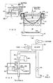
- FIG. 3 there is illustrated an apparatus of the present invention.
- the apparatus of Fig. 3 is identical to that of Fig. 1 with the exception that a bubble detector 40 is positioned between valve 33 and mixer 32.
- FIG. 4 there is illustrated an enlarged cross-sectional view of portion IV of Fig. 3 which is unique to the present invention.
- flow meter 60, controller 62 and control valve 64 are positioned and adjusted to insure that the residence time of the water passing therebetween is substantially constant.
- bubble detector 40 is not only designed to detect the presence of bubbles within coolant 15 but it is also designed to detect the presence of bubbles within a predetermined size range. Furthermore, bubble detector 40 will detect the relative density or the number density of these bubbles.
- number density and “relative density” are used interchangeably herein and they both refer to the concentration of bubbles in a volume of liquid.
- bubble detector 40 it is not necessary for bubble detector 40 to actually count the number of bubbles to determine the number density.
- the number density or relative bubble density of the fluid will be determined by comparing the output from bubble detector 40 to a reference. Both the output from detector 40 and the reference are representative of bubble density levels but neither actually needs to be an actual bubble count.
- bubble detector 40 discriminates between bubbles which are useful for a given application and other bubbles which are less useful.
- useful bubbles are those which contribute to insulation layer 34 (shown in Fig. 2) and bubbles which are excessively large gas bubbles which do not significantly contribute to insulation layer 34.
- Bubble detector 40 comprises a light source 42, an aperture 44 and a sensor 46.
- the size and location of bubble detector 40 is such that it can continuously monitor the amount of small gas bubbles and evolving micron sized gas bubbles in the coolant prior to the coolant contacting the surface of ingot 16.
- Bubble detector 40 is connected to a microprocessor 39 which continuously calculates the optimum flow rate for the gas entering mixer 32. Microprocessor 39 performs this task by adjusting valve 41.
- Light source 42 is positioned near a window 48 in conduit 50. Because of the scattering and low intensity of incandescent light, the preferred light source is laser light. Conduit 50 also contains a second window 52. Windows 48 and 52 are both transparent to the light emitting from light source 42. Windows 48 and 52 may be made of, for example, glass and are affixed to conduit 50 to prevent the loss of fluid.
- Aperture 44 is positioned near sensor 46 and window 52, in such a manner that light emitted from light source 42 must pass through window 52 and aperture 44 before reaching sensor 46.
- Aperture 44 can be positioned adjacent to window 52 and outside conduit 50, as shown in Fig. 4, or it can be positioned within conduit 50.
- Sensor 46 is a photoconductive cell or photoelectric conversion element such as, for example, CdS or the like which is fixed to conduit 50. It is well known that the electric resistance value of the photoconductive cell will change in accordance with the intensity of light incident on the photoconductive cell.
- the photoconductive cell in sensor 46 is connected to microprocessor 39. The change in resistance in the photoconductive cell provides a continuous signal to microprocessor 39. The signal strength is related to the number density of the bubbles that are within a reference size range.
- Microprocessor 39 continuously compares the signal from sensor 46 to a reference signal range of signals.
- microprocessor 39 sends a command signal to a control (not shown) on valve 41 to either open or close the valve.
- the command will cause the valve to change by one increment. Since microprocessor 39 is continuously comparing the signal from sensor 46 to a reference signal, the opening in valve 41 will be changed by successive increments until the gas flow rate and thus the electrical input resistance from sensor 46 is within the reference range.
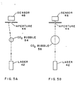
- valve 64 is controlled by controller 62 to establish a standard residence time for the water passing between flow meter 60 and valve 64. If for example, water 15 is introduced into conduit 50 without any bubbles therein, light radiated from light source 42 through windows 48 and 52 and aperture 44, will hit sensor 46 and will cause microprocessor to register a base level electrical resistance input fora standard volume of water passing through the path of the light. When water 15 contains gas bubbles, light passing through conduit 50 will intercept a gas bubble as shown in either Fig. 5A or 5B.
- valve 64 will act to release the pressure in the system to a lower controlled pressure so that the bubble size and bubble density of the bubbles being detected is representative of the bubble size and bubble density of the water that is being applied to the surface of the emerging ingot.
- the size and number density of the bubbles in conduit 50 need not be of the exact size and number as those being applied to the surface of the ingot.
- the bubble detector will need to be properly calibrated so that the microprocessor will be able to correctly determine if the generated input signal is too large or too small so that valve 41 can be adjusted accordingly.
- conduit 50 If light passing through conduit 50 intercepts a gas bubble that is small in relation to the size of aperture 44, the light will take the path shown in Fig. 5A.
- the size of the aperture must be such that the light will not go through the aperture but will take the path shown in Fig. 5A.
- microprocessor 39 continuously compares the signal from sensor 46 to a reference signal or range of signals. Based on this comparison, microprocessor 39 will then send a command signal to adjust valve 41 which controls the flow of gas.
- microprocessor 39 can continuously monitor changes in the electrical resistance from the photoconductive cell due to the presence of small bubbles in the water. From this continuous monitoring, microprocessor 39 is continuously calculating whether the concentration of small bubble in the liquid coolant is in a range that has be determined to produce optimum heat transfer of the water stream as it is to be used for cooling the surface of ingot 16. Microprocessor 39 can instantaneously calculate the optimum flow rate for gas entering mixer 32 and open or close valve 41 to bring the electrical resistance input from sensor 46, and thus the small bubble concentration, to within a reference range.
- the reference operating range of electrical resistance for sensor 46 may be programed into microprocessor 39 with reference to the size of the ingot, the composition of the ingot which is being cast and the stage of casting, the position of the bottom block or the elapsed time in the casting operation.
- conduit 50 If the light passing through conduit 50 intercepts an excessively large gas bubble 56, for instance of the size that may not contribute to the formation of insulating layer 34 (shown in Fig. 2), the light will take the path shown in Fig. 58.
- the size of aperture 44 is selected such that light hitting an excessively large bubble 56 will not be deflected and will pass through the aperture.
- bubble 56 can be considered to be excessively large if it is generally above the size of a millimeter.
- other gas-liquid systems may find a bubble size above a millimeter acceptable in which case, aperture 44 may be increased to accommodate such.
- the size of aperture 44 acts to influence the sensitivity of the system to bubble size.
- the size of aperture 44 will determine if light hitting small bubble 54 will pass therethrough or be deflected or scattered. By varying the size of the aperture, one can vary the size of the bubbles that scatter light outside the aperture and decrease the intensity of the light incident on the photoconductive cell.
- bubble detector 40 to discriminate between small bubbles 54 and excessively large bubbles 56 permits it to infer the volatility of the water stream and its heat transfer characteristics without the need to continually monitor the temperature of the water and/or water quality, gas flow rate and mixer effectiveness.
- the heat transfer characteristics of the liquid is related to the ability of the liquid to hold small bubbles.
- the ability of the liquid to hold small bubbles is dependent on the temperature of the water, the quality of the water and mixer effectiveness.
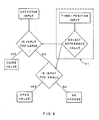
- Fig. 6 is a logic and process flow diagram showing decisions of the process in controlling the flow of gas into the mixer. Essentially the procedure followed in the process include the following steps:
- Section VI of Fig. 6 shows an optional procedure that may be used in practicing the present invention.
- the initial casting rate of a continuously cast ingot is slower than the casting rate during the bulk of the casting process.
- the butt end of the ingot lies adjacent a starting block rather than contiguous metal.
- the initial ingot cooling rate is therefore considerably higher than the cooling rate under steady state running conditions. Slow casting rates and rapid solidification at the start of a casting sequence combine to create a need for a fluid having a lower cooling capacity during the initial stages of solidification shrinkage in the butt end of the ingot.
- the predetermined reference value may be varied with time, withdrawal rate and/or the position of the bottom block to compensate for this need.
- a first value may be used that allows more CO2 into the mixer than during the steady state condition.
- Microprocessor may be programmed to automatically change to a steady state reference value after a predetermined period of time into the cast or after the bottom block has reached a certain position.
- the reference valve may vary gradually from a first value to a second value to reflect the gradual transition form the start-up phase to the steady state phase of casting.
- the switch from a first start-up reference value to a second steady state reference value may also be control led manually.
- Section VI of Fig. 6 illustrates an optional procedure of the control system used in controlling the flow of gas into the mixer. Essentially the procedure of Section VI comprises the following steps:
- the apparatus of the present invention will be especially valuable in the casting of alloys having a short solidification range. As discussed above, alloys having short solidification are especially sensitive to ingot butt curl.
- the apparatus of the present invention will be valuable in the casting of alloys which are difficult to cast without cracking such as aluminum-lithium alloys and alloys containing zirconium.
- the present invention has been found useful in casting ingots of Aluminum Association Alloys in the 7XXX and 2XXX series alloys which have a large width to thickness ratio. However, the invention may be practiced on all alloys.
- Metals suitable for treatment with the present invention include aluminum, magnesium, copper, iron, nickel, cobalt, zinc, and alloys thereof.
- the apparatus of the present invention will be valuable in operations other than the casting of alloys.
- the apparatus maybe used in an operation in which the liquid is not being used to cool, but rather is being used to heat an object.
- the method and apparatus of the present invention are directed to controllling the heat exchange capacity of a liquid.
- the method and apparatus of the present invention will have chemical and medical applications in that require sensitive temperature control.
- the injection of gas bubbles into a hot liquid may be performed for the purpose of increasing the cooling capacity of the liquid and thus decreasing either the rate of reaction or the volatility of the reaction.
- the bubble detector of the present invention may use other than a laser as a source of light.
- incandescent light may be used in conjunction with convergent lens which focus a light source that otherwise would be too weak for use in the present invention.
- the light extinction can be represented by the following: 1 -e- KNL where K is constant; N is the bubble number density and L is the distance between windows 48 and 52.
- means other than a light source may be used to detect bubbles and, if desired, infer the heat transfer characteristics of the liquid coolant which is used.
- a sonic means can be used to detect bubbles.
- means other than non-intrusive means may be used in practicing the present invention.
- a system utilizing fiber optic probes which are placed into the flowing liquid coolant may also be used.
- the present invention has been described in terms of a bubble detector that discriminates between small bubbles that evolve from gas dissolved in a liquid and larger bubbles that may be less effective, it is not so limited.
- the aperture of the bubble detector can be reduced so that the presence of bubbles significantly larger than larger than micron sized bubbles can be detected.
- the present invention can be used to detect the number density of relatively large bubbles which are formed from gas that is entrained in a liquid coolant as a mass of bubbles that tend to remain discrete and undissolved.
- the apparatus and system of the present invention utilizes a microprocessor which send signals to a control which opens and closes valve 41 and thus change the flow of gas into the mixer
- the microprocessor can be also connected to a device that opens and closes a valve which changes the flow of fluid into the mixer.
- the microprocessor can be also connected to a devices that opens and closes valves which change the flow of gas and/or fluid into the mixer.
- the microprocessor will be programmed to calculate the optimum mixture of gas and fluid and determine whether the gas or fluid valve needs to be adjusted.
- the improved monitoring capacity of the present invention can be utilized to automate a the casting of ingot having a rectangular cross-section which possesses a larger width to thickness ratios than has heretofore been commercially feasible. It would be highly desirable to be able to cast ingots without regard to their width to thickness ratio. This is because larger width to thickness ratios require fewer passes in the rolling mill and therefore less time, effort and money spent in rolling the ingots into sheets and plates.
- ingot casting molds can be designed for receiving liquid coolant from more than one source with each source of liquid coolant connected to a bubble detector that has been separately programmed. The flow from several separately programmed bubble detectors can then be combined to create a variation in the concentration of the small bubbles in the of water on the emerging ingot. The variation in the concentration of the small bubbles across surface of a rectangular ingot can be designed to compensate for the variation in the cooling characteristics of the rectangular ingot. In this manner, the center of the width of the ingot can be cooled at a rate that is different than the edge.
- the variation in the concentration of the small bubbles in the water blanket can be used to retard the cooling in the corners and along the shorter sidewalls of a rectangular ingots and thus reduce the variation in the ingots surface cooling and thus allow those skilled in the art to cast at higher width to thickness ratios than have been commercially feasible without a decrease in safety.
- the gases comprehended by the present invention include any gas or chemical that is more volatile than the liquid cooling medium or chemical that releases gases when it comes into contact with a hot surface.
- Gases that may be used when water is used as the coolant include but are not limited to, carbon dioxide, air, oxygen, nitrogen, furnace gas and mixtures thereof.
- the preferred gas is air which is entrained in water as a mass of bubbles that tend to remain discrete and undissolved as the water is directed at the surface of an emerging ingot.
- the invention of the present invention has been described in terms of a gas that is mixed in a flowing liquid, the invention is also intended to include a liquid coolant being mixed into a flowing gas. Those skilled in the art will recognize that the bubble detector will then be used to detect droplets of liquid coolant suspended in the gas.
- casting may be done in other known casting methods, such as DC casting or EM casting.
- the casting may be accomplished in other than vertical casting systems.
- the casting may be performed in the horizontal direction, as described in U.S. Patent 4,474,225, issued to Ho Yu October 2, 1984.
- the casting need not be continuous but may be intermittent.
Landscapes
- Engineering & Computer Science (AREA)
- Mechanical Engineering (AREA)
- Continuous Casting (AREA)
Applications Claiming Priority (2)
| Application Number | Priority Date | Filing Date | Title |
|---|---|---|---|
| US07/366,759 US4987950A (en) | 1989-06-14 | 1989-06-14 | Method and apparatus for controlling the heat transfer of liquid coolant in continuous casting |
| US366759 | 1989-06-14 |
Publications (2)
| Publication Number | Publication Date |
|---|---|
| EP0402692A2 true EP0402692A2 (fr) | 1990-12-19 |
| EP0402692A3 EP0402692A3 (fr) | 1992-04-22 |
Family
ID=23444382
Family Applications (1)
| Application Number | Title | Priority Date | Filing Date |
|---|---|---|---|
| EP19900110124 Withdrawn EP0402692A3 (fr) | 1989-06-14 | 1990-05-29 | Procédé et dispositif pour le contrôle de la transmission de chaleur d'agents refroidisseurs liquides en coulée continue |
Country Status (6)
| Country | Link |
|---|---|
| US (1) | US4987950A (fr) |
| EP (1) | EP0402692A3 (fr) |
| JP (1) | JPH0323045A (fr) |
| AU (1) | AU632136B2 (fr) |
| CA (1) | CA2018016C (fr) |
| NO (1) | NO902636L (fr) |
Cited By (7)
| Publication number | Priority date | Publication date | Assignee | Title |
|---|---|---|---|---|
| EP0497254A3 (en) * | 1991-01-28 | 1992-12-30 | Aluminum Company Of America | Method and apparatus for controlling the heat transfer of liquid coolant in continuous casting |
| GB2336905A (en) * | 1998-04-29 | 1999-11-03 | Wrc Plc | Method and apparatus for monitoring bubbles in a liquid |
| WO2010094852A1 (fr) * | 2009-02-20 | 2010-08-26 | Alcan Rhenalu | Procédé de coulée pour alliages d'aluminium |
| EP2664398A3 (fr) * | 2012-05-17 | 2013-12-18 | Almex USA, Inc. | Appareil de coulée d'alliages d'aluminium-lithium |
| EP3117931A1 (fr) * | 2013-02-04 | 2017-01-18 | Almex USA, Inc. | Appareil permettant de minimiser le risque d'explosions dans le moulage en coquille d'alliages aluminium-lithium |
| RU2639901C2 (ru) * | 2012-05-17 | 2017-12-25 | ОЛМЕКС ЮЭсЭй, ИНК. | Способ и устройство для минимизации вероятности взрывов при литье с прямым охлаждением алюминиево-литиевых сплавов |
| US9936541B2 (en) | 2013-11-23 | 2018-04-03 | Almex USA, Inc. | Alloy melting and holding furnace |
Families Citing this family (20)
| Publication number | Priority date | Publication date | Assignee | Title |
|---|---|---|---|---|
| JPH0557400A (ja) * | 1991-05-15 | 1993-03-09 | Sumitomo Light Metal Ind Ltd | アルミニウムの連続鋳造法及びその装置 |
| US5226950A (en) * | 1992-06-16 | 1993-07-13 | Aluminum Company Of America | Liquid-in-liquid sensor and method |
| DE19518945C2 (de) * | 1995-05-23 | 1998-09-17 | Siemens Ag | Verfahren und Vorrichtung zum Bestimmen des Wärmetransportmechanismus an wenigstens einer Grenzfläche zwischen einem Festkörper und einer Flüssigkeit |
| US6264767B1 (en) | 1995-06-07 | 2001-07-24 | Ipsco Enterprises Inc. | Method of producing martensite-or bainite-rich steel using steckel mill and controlled cooling |
| US5918473A (en) * | 1997-05-09 | 1999-07-06 | Alcan International Limited | Method and apparatus for measuring quenchant properties of coolants |
| US6056041A (en) * | 1997-06-12 | 2000-05-02 | Alcan International Limited | Method and apparatus for controlling the temperature of an ingot during casting, particularly at start up |
| WO2000003042A1 (fr) | 1998-07-10 | 2000-01-20 | Ipsco Inc. | Procede et appareil de production d'acier riche en martensite ou bainite au moyen d'un laminoir de type steckel et de refroidissement regule |
| US6470959B1 (en) * | 2000-09-18 | 2002-10-29 | Alcan International Limited | Control of heat flux in continuous metal casters |
| US7216691B2 (en) * | 2002-07-09 | 2007-05-15 | Alotech Ltd. Llc | Mold-removal casting method and apparatus |
| ATE547194T1 (de) * | 2002-07-11 | 2012-03-15 | Cons Eng Co Inc | Verfahren zur entfernung der sanformen von gussstücken |
| US7165600B2 (en) * | 2002-09-11 | 2007-01-23 | Alotech Ltd. Llc | Chemically bonded aggregate mold |
| WO2004026504A1 (fr) * | 2002-09-20 | 2004-04-01 | Alotech Ltd. Llc | Procede et appareil de moulage a modele perdu et retrait de moule |
| US7121318B2 (en) * | 2002-09-20 | 2006-10-17 | Alotech Ltd. Llc | Lost pattern mold removal casting method and apparatus |
| US20050003387A1 (en) * | 2003-02-21 | 2005-01-06 | Irm Llc | Methods and compositions for modulating apoptosis |
| US7267158B2 (en) * | 2003-07-02 | 2007-09-11 | Alcoa Inc. | Control of oxide growth on molten aluminum during casting using a high moisture atmosphere |
| US7007739B2 (en) | 2004-02-28 | 2006-03-07 | Wagstaff, Inc. | Direct chilled metal casting system |
| BRPI0502779B1 (pt) * | 2005-06-09 | 2020-09-29 | Usinas Siderúrgicas De Minas Gerais S.A. - Usiminas | Dispositivo para medição contínua de temperatura do aço líquido no distribuidor com pirômetro infravermelho e fibra óptica |
| WO2013092103A1 (fr) * | 2011-12-22 | 2013-06-27 | Endress+Hauser Flowtec Ag | Procédé servant à détecter une précipitation de gouttelettes sur une sonde de température chauffée |
| US11951536B2 (en) * | 2020-07-23 | 2024-04-09 | Novelis Inc. | System and method for monitoring ingot detachment from bottom block |
| KR102805134B1 (ko) * | 2020-07-23 | 2025-05-12 | 노벨리스 인크. | 금속 주조 시스템의 이벤트 감지 |
Family Cites Families (27)
| Publication number | Priority date | Publication date | Assignee | Title |
|---|---|---|---|---|
| US3136325A (en) * | 1962-05-24 | 1964-06-09 | Cities Service Oil Co | Controlled addition of gas to liquid |
| US3344840A (en) * | 1966-07-01 | 1967-10-03 | Crucible Steel Co America | Methods and apparatus for producing metal ingots |
| GB1109269A (en) * | 1966-07-29 | 1968-04-10 | Mepag Ag | Determining the boiling points of liquids |
| US3441079A (en) * | 1966-10-24 | 1969-04-29 | Aluminium Lab Ltd | Casting of aluminum ingots |
| DE1802269C3 (de) * | 1968-10-10 | 1979-09-27 | Kernforschungszentrum Karlsruhe Gmbh, 7500 Karlsruhe | Verfahren zum Messen der Konzentration und/oder Größe von Schwebstoffteilchen |
| US3680962A (en) * | 1969-09-08 | 1972-08-01 | Tokyo Keiki Seizosho Co Ltd | Contaminant detector comprising means for selectively applying pressure to liquify bubbles |
| CH552423A (de) * | 1972-04-18 | 1974-08-15 | Concast Ag | Verfahren und vorrichtung zum steuern des waermeentzuges in kokillen beim stranggiessen. |
| CH553608A (de) * | 1972-12-05 | 1974-09-13 | Concast Ag | Verfahren zum stahlstranggiessen und stahlstranggiessanlage. |
| GB1473095A (fr) * | 1973-04-30 | 1977-05-11 | ||
| GB1482350A (en) * | 1973-09-17 | 1977-08-10 | Atomic Energy Authority Uk | Ultra sonic testing |
| US3974681A (en) * | 1973-10-23 | 1976-08-17 | Jerry Namery | Ultrasonic bubble detector |
| US4138879A (en) * | 1977-08-22 | 1979-02-13 | Tif Instruments, Inc. | Sightless bubble detector |
| US4166495A (en) * | 1978-03-13 | 1979-09-04 | Aluminum Company Of America | Ingot casting method |
| US4344429A (en) * | 1979-12-13 | 1982-08-17 | Baxter Travenol Laboratories, Inc. | Bubble detector with feedback circuit for improved sensitivity |
| JPS5719144A (en) * | 1980-07-10 | 1982-02-01 | Nippon Steel Corp | Conveying method for high-temperature ingot |
| JPS57127505A (en) * | 1981-01-22 | 1982-08-07 | Nippon Steel Corp | Direct rolling manufacturing device for steel |
| US4474225A (en) * | 1982-05-24 | 1984-10-02 | Aluminum Company Of America | Method of direct chill casting |
| JPS59135852U (ja) * | 1983-02-25 | 1984-09-11 | 株式会社神戸製鋼所 | 連続鋳造設備に用いる冷却用ミスト噴出装置 |
| EP0127577A3 (fr) * | 1983-05-26 | 1986-12-30 | Schweizerische Aluminium Ag | Procédé pour la coulée continue d'un lingot en particulier en aliminium ou un alliage d'aluminium |
| US4540283A (en) * | 1983-06-20 | 1985-09-10 | Bachalo William D | Apparatus and method for determining the size and velocity of particles, droplets, bubbles or the like using laser light scattering |
| US4779762A (en) * | 1984-05-30 | 1988-10-25 | Nordson Corporation | Method and apparatus for controlling the gas content of dispensed hot melt thermoplastic adhesive foam |
| US4659218A (en) * | 1985-05-23 | 1987-04-21 | Canadian Patents & Development Corporation | Multi-probe system for measuring bubble characteristics gas hold-up, liquid hold-up and solid hold-up in a three-phase fluidized bed |
| US4627726A (en) * | 1985-06-17 | 1986-12-09 | The Johns Hopkins University | Method and apparatus using laser radiation for generating and measuring gas bubbles |
| US4660619A (en) * | 1985-07-23 | 1987-04-28 | Continuous Casting Systems Inc. | Mold cooling apparatus and method for continuous casting machines |
| US4662749A (en) * | 1985-11-08 | 1987-05-05 | Massachusetts Institute Of Technology | Fiber optic probe and system for particle size and velocity measurement |
| US4693298A (en) * | 1986-12-08 | 1987-09-15 | Wagstaff Engineering, Inc. | Means and technique for casting metals at a controlled direct cooling rate |
| JPH0790340B2 (ja) * | 1987-09-09 | 1995-10-04 | 住友金属工業株式会社 | ミスト冷却の最適空気量制御方法 |
-
1989
- 1989-06-14 US US07/366,759 patent/US4987950A/en not_active Expired - Lifetime
-
1990
- 1990-05-29 EP EP19900110124 patent/EP0402692A3/fr not_active Withdrawn
- 1990-05-31 CA CA002018016A patent/CA2018016C/fr not_active Expired - Fee Related
- 1990-06-13 NO NO90902636A patent/NO902636L/no unknown
- 1990-06-13 AU AU57055/90A patent/AU632136B2/en not_active Ceased
- 1990-06-13 JP JP2155022A patent/JPH0323045A/ja active Pending
Cited By (25)
| Publication number | Priority date | Publication date | Assignee | Title |
|---|---|---|---|---|
| EP0497254A3 (en) * | 1991-01-28 | 1992-12-30 | Aluminum Company Of America | Method and apparatus for controlling the heat transfer of liquid coolant in continuous casting |
| GB2336905A (en) * | 1998-04-29 | 1999-11-03 | Wrc Plc | Method and apparatus for monitoring bubbles in a liquid |
| GB2336905B (en) * | 1998-04-29 | 2003-07-02 | Wrc Plc | Apparatus for monitoring bubbles in a liquid |
| WO2010094852A1 (fr) * | 2009-02-20 | 2010-08-26 | Alcan Rhenalu | Procédé de coulée pour alliages d'aluminium |
| FR2942479A1 (fr) * | 2009-02-20 | 2010-08-27 | Alcan Rhenalu | Procede de coulee pour alliages d'aluminium |
| CN102325611A (zh) * | 2009-02-20 | 2012-01-18 | 法国肯联铝业 | 铝合金的铸造方法 |
| CN102325611B (zh) * | 2009-02-20 | 2013-09-04 | 法国肯联铝业 | 铝合金的铸造方法 |
| RU2639185C2 (ru) * | 2012-05-17 | 2017-12-20 | ОЛМЕКС ЮЭсЭй, ИНК. | Устройство для разливки алюминиево-литиевых сплавов |
| US10646919B2 (en) | 2012-05-17 | 2020-05-12 | Almex USA, Inc. | Process and apparatus for direct chill casting |
| CN104470655A (zh) * | 2012-05-17 | 2015-03-25 | 美国阿尔美有限公司 | 用于铸造铝锂合金的装置 |
| EP4173738A1 (fr) * | 2012-05-17 | 2023-05-03 | Almex USA, Inc. | Appareil pour couler des alliages d'aluminium et de lithium |
| US10946440B2 (en) | 2012-05-17 | 2021-03-16 | Almex USA, Inc. | Process and apparatus for minimizing the potential for explosions in the direct chill casting aluminum alloys |
| EP2664398A3 (fr) * | 2012-05-17 | 2013-12-18 | Almex USA, Inc. | Appareil de coulée d'alliages d'aluminium-lithium |
| RU2639901C2 (ru) * | 2012-05-17 | 2017-12-25 | ОЛМЕКС ЮЭсЭй, ИНК. | Способ и устройство для минимизации вероятности взрывов при литье с прямым охлаждением алюминиево-литиевых сплавов |
| US9849507B2 (en) | 2012-05-17 | 2017-12-26 | Almex USA, Inc. | Process and apparatus for minimizing the potential for explosions in the direct chill casting of aluminum lithium alloys |
| US9895744B2 (en) | 2012-05-17 | 2018-02-20 | Almex USA, Inc. | Process and apparatus for direct chill casting |
| WO2013173655A3 (fr) * | 2012-05-17 | 2014-02-20 | Almex USA, Inc. | Appareil de coulée d'alliages aluminium/lithium |
| US9950360B2 (en) | 2013-02-04 | 2018-04-24 | Almex USA, Inc. | Process and apparatus for minimizing the potential for explosions in the direct chill casting of lithium alloys |
| RU2675127C2 (ru) * | 2013-02-04 | 2018-12-17 | ОЛМЕКС ЮЭсЭй, ИНК. | Способ и устройство для минимизации взрывного потенциала при литье с прямым охлаждением сплавов алюминия и лития |
| RU2678848C2 (ru) * | 2013-02-04 | 2019-02-04 | ОЛМЕКС ЮЭсЭй, ИНК. | Способ и устройство для литья с прямым охлаждением |
| US10864576B2 (en) | 2013-02-04 | 2020-12-15 | Almex USA, Inc. | Process and apparatus for minimizing the potential for explosions in the direct chill casting of lithium alloys |
| US9764380B2 (en) | 2013-02-04 | 2017-09-19 | Almex USA, Inc. | Process and apparatus for direct chill casting |
| EP3117931A1 (fr) * | 2013-02-04 | 2017-01-18 | Almex USA, Inc. | Appareil permettant de minimiser le risque d'explosions dans le moulage en coquille d'alliages aluminium-lithium |
| US9936541B2 (en) | 2013-11-23 | 2018-04-03 | Almex USA, Inc. | Alloy melting and holding furnace |
| US10932333B2 (en) | 2013-11-23 | 2021-02-23 | Almex USA, Inc. | Alloy melting and holding furnace |
Also Published As
| Publication number | Publication date |
|---|---|
| EP0402692A3 (fr) | 1992-04-22 |
| NO902636L (no) | 1990-12-17 |
| US4987950A (en) | 1991-01-29 |
| NO902636D0 (no) | 1990-06-13 |
| CA2018016C (fr) | 1996-01-16 |
| JPH0323045A (ja) | 1991-01-31 |
| AU632136B2 (en) | 1992-12-17 |
| CA2018016A1 (fr) | 1990-12-14 |
| AU5705590A (en) | 1990-12-20 |
Similar Documents
| Publication | Publication Date | Title |
|---|---|---|
| US4987950A (en) | Method and apparatus for controlling the heat transfer of liquid coolant in continuous casting | |
| US5148853A (en) | Method and apparatus for controlling the heat transfer of liquid coolant in continuous casting | |
| US4552200A (en) | Control in continuous casting to enhance feeding | |
| Thomas | Fluid flow in the mold | |
| KR20010023598A (ko) | 전자기장을 사용하여 연속 주조중의 금속흐름을 제어하는방법 및 장치 | |
| EP0192774B1 (fr) | Procede de coulee continue de metaux | |
| WO2005062846A2 (fr) | Commande du panier de coulee | |
| KR100462913B1 (ko) | 연속 주조 빌릿 및 그 제조방법 | |
| US4306610A (en) | Method of controlling continuous casting rate | |
| JP2000079451A (ja) | タンディッシュと、そのタンディッシュを用いた希土類元素含有合金の製造方法 | |
| EP0150922A2 (fr) | Coulée de métaux légers | |
| KR101165478B1 (ko) | 고순도 주물 금속 빌릿을 형성하기 위한 순차적 주조 방법 | |
| KR101267341B1 (ko) | 연주공정에서 응고쉘의 브레이크아웃 방지 장치 및 그 방법 | |
| JP2914817B2 (ja) | 連続鋳造における欠落鋳造方法 | |
| WO2005042183A1 (fr) | Procede et dispositif de detection de laitier | |
| JPH04238648A (ja) | 薄板連続鋳造装置 | |
| JPH04294850A (ja) | 多ストランド連鋳機のブレークアウト検知方法 | |
| JPS62197257A (ja) | 連続鋳造における溶鋼の注入方法 | |
| SU961850A1 (ru) | Способ непрерывной разливки металла на сл бы | |
| US4588018A (en) | Control in continuous casting to enhance feeding | |
| JPH0341884Y2 (fr) | ||
| JPH04143054A (ja) | 連続鋳造の割れ性ブレークアウト防止方法 | |
| JPS5788958A (en) | Continuous casting method | |
| JPH04238649A (ja) | 薄板連続鋳造装置 | |
| Honeycutt et al. | Tundish for Direct Casting of Metal Strip |
Legal Events
| Date | Code | Title | Description |
|---|---|---|---|
| PUAI | Public reference made under article 153(3) epc to a published international application that has entered the european phase |
Free format text: ORIGINAL CODE: 0009012 |
|
| AK | Designated contracting states |
Kind code of ref document: A2 Designated state(s): BE CH DE FR GB IT LI |
|
| 17P | Request for examination filed |
Effective date: 19901220 |
|
| PUAL | Search report despatched |
Free format text: ORIGINAL CODE: 0009013 |
|
| AK | Designated contracting states |
Kind code of ref document: A3 Designated state(s): BE CH DE FR GB IT LI |
|
| 17Q | First examination report despatched |
Effective date: 19940223 |
|
| STAA | Information on the status of an ep patent application or granted ep patent |
Free format text: STATUS: THE APPLICATION IS DEEMED TO BE WITHDRAWN |
|
| 18D | Application deemed to be withdrawn |
Effective date: 19960109 |