EP0402701A2 - Procédé et appareil de fabrication d'un guide d'ondes optique - Google Patents
Procédé et appareil de fabrication d'un guide d'ondes optique Download PDFInfo
- Publication number
- EP0402701A2 EP0402701A2 EP90110218A EP90110218A EP0402701A2 EP 0402701 A2 EP0402701 A2 EP 0402701A2 EP 90110218 A EP90110218 A EP 90110218A EP 90110218 A EP90110218 A EP 90110218A EP 0402701 A2 EP0402701 A2 EP 0402701A2
- Authority
- EP
- European Patent Office
- Prior art keywords
- nozzle
- coating
- glass fiber
- centering
- chamber
- Prior art date
- Legal status (The legal status is an assumption and is not a legal conclusion. Google has not performed a legal analysis and makes no representation as to the accuracy of the status listed.)
- Granted
Links
Images


Classifications
-
- C—CHEMISTRY; METALLURGY
- C03—GLASS; MINERAL OR SLAG WOOL
- C03C—CHEMICAL COMPOSITION OF GLASSES, GLAZES OR VITREOUS ENAMELS; SURFACE TREATMENT OF GLASS; SURFACE TREATMENT OF FIBRES OR FILAMENTS MADE FROM GLASS, MINERALS OR SLAGS; JOINING GLASS TO GLASS OR OTHER MATERIALS
- C03C25/00—Surface treatment of fibres or filaments made from glass, minerals or slags
- C03C25/10—Coating
- C03C25/12—General methods of coating; Devices therefor
-
- C—CHEMISTRY; METALLURGY
- C03—GLASS; MINERAL OR SLAG WOOL
- C03C—CHEMICAL COMPOSITION OF GLASSES, GLAZES OR VITREOUS ENAMELS; SURFACE TREATMENT OF GLASS; SURFACE TREATMENT OF FIBRES OR FILAMENTS MADE FROM GLASS, MINERALS OR SLAGS; JOINING GLASS TO GLASS OR OTHER MATERIALS
- C03C25/00—Surface treatment of fibres or filaments made from glass, minerals or slags
- C03C25/10—Coating
- C03C25/12—General methods of coating; Devices therefor
- C03C25/18—Extrusion
Definitions
- the present invention relates to a method for producing an optical waveguide and to an apparatus for carrying out the method.
- the glass fiber of optical fibers is coated in such a way that the glass fiber runs centrally to the coating while maintaining a tolerance range. To ensure this, the glass fiber must be pulled centrally through the coating nozzle. This requires a very precise, time-consuming adjustment of the system parts of a fiber drawing tower. Nevertheless, the eccentricity of the glass fiber can exceed the tolerance limit by changing the position of system parts, for example due to changes in temperature, which necessitates a time-consuming readjustment.
- EP-B 0 178 107 In order to be able to adjust and adjust the centricity of the glass fiber with respect to the coating in a simple manner, it is known from EP-B 0 178 107 to arrange the entire coating device at or near the outlet opening of the coating nozzle so as to be tiltable about two mutually perpendicular axes. The adjustment or readjustment is carried out in such a way that the centricity of the coated glass fiber emerging from the coating nozzle is measured and the device is pivoted in accordance with an existing eccentricity so that the eccentricity is reduced.
- the necessary manipulated variables are generated in that two laser beams offset by 90 ° are directed onto the emerging coated glass fiber and the scattering patterns that occur are imaged on transparent discs. The scattering patterns are evaluated electronically and the necessary manipulated variables are generated from existing asymmetries and servomotors are fed to adjust the device.
- the present invention is also based on the object of specifying a method and a device with which an adjustment or readjustment of the centricity of the glass fiber is possible in a simple manner and without great expenditure of time.
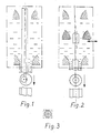
- Fig. 1 denotes a device for applying a layer 3 of lacquer or plastic on a glass fiber 2. This has an upper blocking nozzle 4 with a nozzle funnel 5 and a lower coating nozzle 6 with a nozzle funnel 7, which merges into the nozzle mouth 8.
- the blocking nozzle 4 and the coating nozzle 6 are centered with respect to one another such that their nozzle axes lie on the imaginary central axis 9.
- a chamber 10 is formed, which from the outside with a predetermined pressure of e.g. 1 to 2 bar is flooded with a liquid to pasteous, curable or self-curing coating material 11.
- the glass fiber 2 is pulled in the fiber pulling direction 12 from top to bottom so that it does not touch the blocking nozzle 4 and the coating nozzle 6 and in particular so that the center line 13 of the glass fiber 2 coincides with the central axis 9 if possible.
- 1 shows an undesirable change in the position of the glass fiber 2 with respect to the central axis 9.
- the glass fiber 2 is then no longer pulled centrally through the coating nozzle 6 and the nozzle mouth 8, and the glass fiber 2 is accordingly surrounded by the coating material 11 when it leaves the coating nozzle 6 such that it extends eccentrically to the coating 3 formed.
- the eccentricity can be eliminated or reduced to an allowable tolerance limit by providing a centering nozzle 14 with the nozzle funnel 15 in the chamber 10 according to FIG. 2, which is arranged in a direction perpendicular to the central axis 9 extending plane indicated by the arrow 16 is displaceable and adjustable to any point within a hatched or dashed area 17 shown in FIG. 3 about the central axis 9.
- the centering nozzle 14 is now, as shown in FIG. 2, shifted so far, in this case to the right, that the glass fiber 2 is centered out of the nozzle mouth 8 the coating nozzle 6 emerges. A central coating of the glass fiber 2 is thereby achieved.
- the center line 18 of the centering nozzle 14 is against the central axis 9 e.g. offset so far to the right that the glass fiber 2 is deflected so far to the right that its center line 13 also extends in the region of the centering nozzle 14 to the right of the central axis 9 and is then pulled exactly in the center of the nozzle mouth 8.
- FIG. 4 shows a possible construction of a device 1 with a centering nozzle 14.
- This consists of a housing 19 which is closed at the top with the blocking nozzle 4 and at the bottom with the coating nozzle 6 except for the corresponding nozzle openings.
- a chamber 10 is formed between the blocking nozzle 4 and the coating nozzle 6 and is divided into a lower chamber section 21 and an upper chamber section 22 by a perforated plate 20 arranged perpendicular to the central axis 9.
- the centering nozzle 14 is slidably mounted on the plate 20. This can be done by a plurality of adjustment means 23, for example designed as adjusting screws area 17 shown in FIG. 3 can be shifted and adjusted. At least three adjusting means 23 are preferably arranged offset from one another by the same angle ⁇ . These are arranged such that they can be adjusted radially to the central axis 9 in the housing 19 and can be actuated from the outside (FIG. 5), their adjusting heads 24 abutting the circumference 25 of the centering nozzle 14.
- the plate 20 is provided with an opening 26 which extends at least over the area over which the nozzle mouth 27 of the centering nozzle 14 can be displaced.
- Openings 30 are also provided in plate 20, through which the lower and upper chamber sections 21 and 22 are connected to one another, so that both can be supplied with coating material 11.
- the centering nozzle 14 is preferably designed such that the mouth diameter is so large that when the glass fiber 2 is pulled through, more coating material 11 is dragged through the centering nozzle 14 than exits through the coating nozzle 6. Circulation of the coating material 11 from the upper chamber section 22 through the centering nozzle 14 into the lower chamber section 21 and through the openings 30 back to the upper chamber section 22 then occurs, as indicated by the arrows in FIG. 4.
- the openings 30 and the centering nozzle 14 can be arranged and their dimensions can be such that when the centering nozzle 14 is moved, the openings 30 are partially or completely closed or covered or opened or enlarged such that a reduced or increased Circulation of the coating material 11 occurs, which leads to the additional displacement of the glass fiber 2 and thus to the centering thereof.
- the openings 30 designed as round holes are arranged on a circle concentric with the central axis 9 and the centering nozzle 14 is also circular on the outside of the support surface and partially covers all openings 30 in a concentric position (see FIG. 5).
- the openings 30 can also be designed as slots, for example running radially, or as a triangle etc.
- An expedient development of the invention consists in that the centricity of the coated glass fiber 2 emerging from the coating nozzle 6 is measured with respect to its coating 3 and the measurement data are entered into an electronic evaluation system.
- the evaluation electronics generate control signals from the measurement data, which are sent to actuators for adjusting the centering nozzle 14.
- the centering nozzle 14 can be adjusted via the actuators in such a way that an existing eccentricity of the glass fiber 2 with respect to the coating 3 is reduced or completely eliminated.
- the coated glass fiber 2 emerging from the coating nozzle 6 is radially irradiated with two laser beams 31 and 32 from directions orthogonal to one another.This creates a scattering and diffraction pattern on the side of the coated glass fiber 2 facing away from the radiation side, which is applied to a matt screen 33 and 34, respectively.
- the continuous laser beam produces a light spot that is brighter than the other scattering and diffraction lines, whereas the scattering and diffraction lines are shifted towards the coating 3 depending on the eccentricity of the glass fiber 2.
- the scatter and diffraction pattern is symmetrical to this light spot. The latter can therefore be used as a reference for assessing the eccentricity.
- the scattering and diffraction image appearing on the focusing screens 33 and 34 is scanned and recorded by a CCD camera 35 and 36, respectively, and the electrical values derived therefrom are input to evaluation electronics 37.
- evaluation electronics 37 Using the bright light spot as a reference for the symmetry of the scattering and diffraction pattern, this forms corresponding control signals in the presence of asymmetry, which are sent to the corresponding actuators 38, each assigned to an adjusting means 23, e.g. Stepper motors are output.
- the control signals actuate the actuators 38 in such a way that the centering nozzle 14 is adjusted via the setting means 23 in such a way that an existing eccentricity of the glass fiber 2 for the coating 3 is reduced or corrected.
Landscapes
- Life Sciences & Earth Sciences (AREA)
- Chemical & Material Sciences (AREA)
- General Life Sciences & Earth Sciences (AREA)
- Engineering & Computer Science (AREA)
- Chemical Kinetics & Catalysis (AREA)
- General Chemical & Material Sciences (AREA)
- Geochemistry & Mineralogy (AREA)
- Materials Engineering (AREA)
- Organic Chemistry (AREA)
- Application Of Or Painting With Fluid Materials (AREA)
- Optical Fibers, Optical Fiber Cores, And Optical Fiber Bundles (AREA)
Applications Claiming Priority (2)
| Application Number | Priority Date | Filing Date | Title |
|---|---|---|---|
| DE3919067 | 1989-06-10 | ||
| DE3919067A DE3919067A1 (de) | 1989-06-10 | 1989-06-10 | Verfahren und vorrichtung zur herstellung eines lichtwellenleiters |
Publications (3)
| Publication Number | Publication Date |
|---|---|
| EP0402701A2 true EP0402701A2 (fr) | 1990-12-19 |
| EP0402701A3 EP0402701A3 (fr) | 1991-03-20 |
| EP0402701B1 EP0402701B1 (fr) | 1993-03-17 |
Family
ID=6382540
Family Applications (1)
| Application Number | Title | Priority Date | Filing Date |
|---|---|---|---|
| EP90110218A Expired - Lifetime EP0402701B1 (fr) | 1989-06-10 | 1990-05-30 | Procédé et appareil de fabrication d'un guide d'ondes optique |
Country Status (2)
| Country | Link |
|---|---|
| EP (1) | EP0402701B1 (fr) |
| DE (2) | DE3919067A1 (fr) |
Cited By (1)
| Publication number | Priority date | Publication date | Assignee | Title |
|---|---|---|---|---|
| US11105973B2 (en) | 2019-01-11 | 2021-08-31 | Schott Corporation | Optically enhanced high resolution image guides |
Families Citing this family (9)
| Publication number | Priority date | Publication date | Assignee | Title |
|---|---|---|---|---|
| DE4304853A1 (de) * | 1993-02-17 | 1994-08-18 | Coia Gmbh | Verfahren zum Färben von Lichtwellenleitern |
| DE4329716C2 (de) * | 1993-09-03 | 2002-07-18 | Rheydt Kabelwerk Ag | Vorrichtung zum Beschichten einer optischen Faser |
| DE19644350A1 (de) * | 1996-10-25 | 1998-04-30 | Alsthom Cge Alcatel | Verfahren und Vorrichtung zum Herstellen einer optischen Glasfaser |
| DE19646623A1 (de) * | 1996-11-12 | 1998-05-14 | Alsthom Cge Alcatel | Vorrichtung zum Aufbringen eines Beschichtungsmaterials auf eine optische Faser |
| DE29718521U1 (de) * | 1997-10-18 | 1998-01-02 | Alcatel Alsthom Compagnie Générale d'Electricité, Paris | Vorrichtung zum Aufbringen eines Beschichtungsmaterials auf eine Faser |
| DE19801699A1 (de) * | 1998-01-17 | 1999-07-22 | Cit Alcatel | Vorrichtung zum Beschichten einer Faser |
| US7162137B2 (en) * | 2001-06-20 | 2007-01-09 | Ers Company | Optical fiber with nano-particle cladding |
| US7045010B2 (en) * | 2001-09-06 | 2006-05-16 | Alcatel | Applicator for high-speed gel buffering of flextube optical fiber bundles |
| DE10222027A1 (de) * | 2001-12-13 | 2005-04-14 | Zeidl Gmbh | Vorrichtung für eine Lackbeschichtung von Glasfasern |
Family Cites Families (2)
| Publication number | Priority date | Publication date | Assignee | Title |
|---|---|---|---|---|
| NL7902201A (nl) * | 1979-03-21 | 1980-09-23 | Philips Nv | Werkwijze en inrichting voor het vervaardigen van op- tische fibers alsmede optische fibers vervaardigd met de werkwijze. |
| NL8501146A (nl) * | 1985-04-19 | 1986-11-17 | Philips Nv | Inrichting voor het bekleden van optische vezels. |
-
1989
- 1989-06-10 DE DE3919067A patent/DE3919067A1/de not_active Withdrawn
-
1990
- 1990-05-30 EP EP90110218A patent/EP0402701B1/fr not_active Expired - Lifetime
- 1990-05-30 DE DE9090110218T patent/DE59001034D1/de not_active Expired - Fee Related
Cited By (1)
| Publication number | Priority date | Publication date | Assignee | Title |
|---|---|---|---|---|
| US11105973B2 (en) | 2019-01-11 | 2021-08-31 | Schott Corporation | Optically enhanced high resolution image guides |
Also Published As
| Publication number | Publication date |
|---|---|
| DE3919067A1 (de) | 1990-12-13 |
| EP0402701A3 (fr) | 1991-03-20 |
| DE59001034D1 (de) | 1993-04-22 |
| EP0402701B1 (fr) | 1993-03-17 |
Similar Documents
| Publication | Publication Date | Title |
|---|---|---|
| DE69316792T2 (de) | Verfahren zur Herstellung von Polymerisation oder vernetzter Rate-distribuierte Produkte und Verfahren zur Herstellung einer Linse, Linsenanordnung oder Lichtwellenleiter durch dieses Verfahren | |
| DE3015006C2 (de) | Vorrichtung zum Ermitteln der Topographie der Charge in einem Hochofen | |
| DE69909136T2 (de) | Rapid-prototyping-vorrichtung und rapid-prototyping-methode | |
| DE102016200043A1 (de) | Verfahren zum Kalibrieren einer Vorrichtung zum Herstellen eines dreidimensionalen Objekts | |
| EP0758952B1 (fr) | Procede et dispositif de fabrication d'objets tridimensionnels | |
| EP0634972A1 (fr) | Procede et dispositif de fabrication d'objets tridimensionnels | |
| DE3101378C2 (de) | Optik zur Ankopplung eines faseroptischen Lichtwellenleiters | |
| EP1525972A1 (fr) | Procédé et dispositif pour chauffer des matériaux plastiques avec des rayons laser | |
| EP0402701B1 (fr) | Procédé et appareil de fabrication d'un guide d'ondes optique | |
| EP3300885A1 (fr) | Procédé d'étalonnage d'un dispositif de fabrication d'un objet tridimensionnel et dispositif réalisé pour la mise en oeuvre du procédé | |
| DE2256736A1 (de) | Verfahren zur automatischen oberflaechenprofilmessung und vorrichtung zur durchfuehrung des verfahrens | |
| EP1048441A1 (fr) | Procédé d'étalonnage d'un appareil pour fabriquer des objets tridimensionnels et appareil d'étalonnage | |
| EP0764079A1 (fr) | Dispositif de production d'un objet a trois dimensions par frittage au laser | |
| DE10297451T5 (de) | Laser-Materialverarbeitungsvorrichtung | |
| DE19531050A1 (de) | Excimerlaserstrahl-Bestrahlungsvorrichtung zum Bearbeiten eines Werkstücks | |
| DE4009089A1 (de) | Mehrfasernhalter fuer ausgangskuppler und verfahren zu dessen anwendung | |
| EP2455711A2 (fr) | Appareil à laser rotatif doté d'un plan de laser incliné et procédé d'alignement d'un appareil à laser rotatif | |
| DE2918100A1 (de) | Automatisiertes justieren in der feinwerktechnik | |
| DE69914271T2 (de) | Pressvorrichtung und optisches Element als gepresstes Produkt | |
| DE19732668C2 (de) | Vorrichtung und Verfahren zur Kalibrierung von Strahlabtastvorrichtungen | |
| DE69113396T2 (de) | Lichthärtungsformungsapparatur. | |
| DE102010032800A1 (de) | Verfahren und Vorrichtung zum Kalibrieren einer Laserbearbeitungsmaschine | |
| EP3702130B1 (fr) | Appareil de stéréolithographie et procédé d'ajustement d'un appareil de stéréolithographie | |
| EP1750891B1 (fr) | Procede de determination de la position focale d'un faisceau laser | |
| DE69801730T2 (de) | Beschichtungsverfahren für optische Faser und Vorrichtung zu dessen Ausführung |
Legal Events
| Date | Code | Title | Description |
|---|---|---|---|
| PUAI | Public reference made under article 153(3) epc to a published international application that has entered the european phase |
Free format text: ORIGINAL CODE: 0009012 |
|
| AK | Designated contracting states |
Kind code of ref document: A2 Designated state(s): DE GB IT NL |
|
| PUAL | Search report despatched |
Free format text: ORIGINAL CODE: 0009013 |
|
| AK | Designated contracting states |
Kind code of ref document: A3 Designated state(s): DE GB IT NL |
|
| 17P | Request for examination filed |
Effective date: 19910218 |
|
| 17Q | First examination report despatched |
Effective date: 19920821 |
|
| GRAA | (expected) grant |
Free format text: ORIGINAL CODE: 0009210 |
|
| ITF | It: translation for a ep patent filed | ||
| AK | Designated contracting states |
Kind code of ref document: B1 Designated state(s): DE GB IT NL |
|
| REF | Corresponds to: |
Ref document number: 59001034 Country of ref document: DE Date of ref document: 19930422 |
|
| GBT | Gb: translation of ep patent filed (gb section 77(6)(a)/1977) |
Effective date: 19930402 |
|
| PLBE | No opposition filed within time limit |
Free format text: ORIGINAL CODE: 0009261 |
|
| STAA | Information on the status of an ep patent application or granted ep patent |
Free format text: STATUS: NO OPPOSITION FILED WITHIN TIME LIMIT |
|
| 26N | No opposition filed | ||
| PGFP | Annual fee paid to national office [announced via postgrant information from national office to epo] |
Ref country code: GB Payment date: 19990413 Year of fee payment: 10 |
|
| PGFP | Annual fee paid to national office [announced via postgrant information from national office to epo] |
Ref country code: DE Payment date: 19990420 Year of fee payment: 10 |
|
| PGFP | Annual fee paid to national office [announced via postgrant information from national office to epo] |
Ref country code: NL Payment date: 19990427 Year of fee payment: 10 |
|
| PG25 | Lapsed in a contracting state [announced via postgrant information from national office to epo] |
Ref country code: GB Free format text: LAPSE BECAUSE OF NON-PAYMENT OF DUE FEES Effective date: 20000530 |
|
| PG25 | Lapsed in a contracting state [announced via postgrant information from national office to epo] |
Ref country code: NL Free format text: LAPSE BECAUSE OF NON-PAYMENT OF DUE FEES Effective date: 20001201 |
|
| GBPC | Gb: european patent ceased through non-payment of renewal fee |
Effective date: 20000530 |
|
| NLV4 | Nl: lapsed or anulled due to non-payment of the annual fee |
Effective date: 20001201 |
|
| PG25 | Lapsed in a contracting state [announced via postgrant information from national office to epo] |
Ref country code: DE Free format text: LAPSE BECAUSE OF NON-PAYMENT OF DUE FEES Effective date: 20010301 |
|
| PG25 | Lapsed in a contracting state [announced via postgrant information from national office to epo] |
Ref country code: IT Free format text: LAPSE BECAUSE OF NON-PAYMENT OF DUE FEES;WARNING: LAPSES OF ITALIAN PATENTS WITH EFFECTIVE DATE BEFORE 2007 MAY HAVE OCCURRED AT ANY TIME BEFORE 2007. THE CORRECT EFFECTIVE DATE MAY BE DIFFERENT FROM THE ONE RECORDED. Effective date: 20050530 |