EP0402740B2 - Procédé pour déterminer la forme d'un réflecteur pour lampe - Google Patents
Procédé pour déterminer la forme d'un réflecteur pour lampe Download PDFInfo
- Publication number
- EP0402740B2 EP0402740B2 EP90110622A EP90110622A EP0402740B2 EP 0402740 B2 EP0402740 B2 EP 0402740B2 EP 90110622 A EP90110622 A EP 90110622A EP 90110622 A EP90110622 A EP 90110622A EP 0402740 B2 EP0402740 B2 EP 0402740B2
- Authority
- EP
- European Patent Office
- Prior art keywords
- reflector
- ellipse
- light
- optical axis
- radiation
- Prior art date
- Legal status (The legal status is an assumption and is not a legal conclusion. Google has not performed a legal analysis and makes no representation as to the accuracy of the status listed.)
- Expired - Lifetime
Links
Images


Classifications
-
- F—MECHANICAL ENGINEERING; LIGHTING; HEATING; WEAPONS; BLASTING
- F21—LIGHTING
- F21V—FUNCTIONAL FEATURES OR DETAILS OF LIGHTING DEVICES OR SYSTEMS THEREOF; STRUCTURAL COMBINATIONS OF LIGHTING DEVICES WITH OTHER ARTICLES, NOT OTHERWISE PROVIDED FOR
- F21V7/00—Reflectors for light sources
- F21V7/04—Optical design
-
- F—MECHANICAL ENGINEERING; LIGHTING; HEATING; WEAPONS; BLASTING
- F21—LIGHTING
- F21V—FUNCTIONAL FEATURES OR DETAILS OF LIGHTING DEVICES OR SYSTEMS THEREOF; STRUCTURAL COMBINATIONS OF LIGHTING DEVICES WITH OTHER ARTICLES, NOT OTHERWISE PROVIDED FOR
- F21V7/00—Reflectors for light sources
- F21V7/04—Optical design
- F21V7/09—Optical design with a combination of different curvatures
-
- Y—GENERAL TAGGING OF NEW TECHNOLOGICAL DEVELOPMENTS; GENERAL TAGGING OF CROSS-SECTIONAL TECHNOLOGIES SPANNING OVER SEVERAL SECTIONS OF THE IPC; TECHNICAL SUBJECTS COVERED BY FORMER USPC CROSS-REFERENCE ART COLLECTIONS [XRACs] AND DIGESTS
- Y10—TECHNICAL SUBJECTS COVERED BY FORMER USPC
- Y10S—TECHNICAL SUBJECTS COVERED BY FORMER USPC CROSS-REFERENCE ART COLLECTIONS [XRACs] AND DIGESTS
- Y10S359/00—Optical: systems and elements
- Y10S359/90—Methods
Definitions
- the invention relates to a reflector for a Luminaire and a method for determining the Form of such a reflector.
- the lights in question here are meant to be especially for illuminating a room Illumination of an object or also for coupling serve from light into a light guide.
- the reflection properties described above of the conic-shaped reflectors can also be done by varying the parameters mentioned generally not be changed.
- the designer is one given certain reflector boundary conditions, according to which the luminaire is to be constructed, for example, the light exit diameter and the length of the lamp due to the structural Given conditions and also the desired one Light distribution at a certain distance from the lamp.
- Elliptical reflectors are often used to illuminate a relatively large area. However, this is the light distribution very inhomogeneous within the beam angle and falls with increasing distance from the optical axis to the outside.
- a reflector is known from US Pat. No. 3,390,262 known in which only a reflector section near the edge corresponds to a conic section, while eir inner reflector section is constructed differently
- the transition between the two mentioned reflector sections is discontinuous.
- the latter has disadvantages in the manufacture of reflectors with regard to Tool. At the discontinuity the reflector cannot work exactly according to the tool be shaped and it gets lively Stray light generated. You have to do with an energy loss count. This is also better known Solution the equalization of the light distribution not reachable to the desired extent.
- From DE-OS 35 07 143 is a lamp known, the reflector consists of segments, which are arranged so that each segment of radiation reflected by another area of the Light source goes out so that points on one too receiving radiation receive radiation, which is reflected by several different segments is.
- the invention has for its object a Possibility to construct reflector shapes to show with the desired light distributions produced with great efficiency as required can be.
- a preparation of the Microstructure of the reflection surface may not be necessary and the reflector should also no seams of a connection from have different curves.
- the two curves between which the invention Reflector runs in particular two different ellipses (i.e. ellipses with at least one different parameter), two different parabolas (i.e. parabolas with different parameters) or an ellipse and be a parabola.
- the reflector shape according to the invention is thus characterized in the latter example, that they are neither a pure ellipse, nor is a pure parabola, but continuous, i.e. over their entire extension, an "in-between" between such conventional known ones Reflector shapes.
- the reflector shape according to the invention does not correspond to a conic section.
- the reflective properties of the invention constructed reflectors are fundamental different from the reflective properties of conical Reflectors and correspond in usually not simple "averages” the reflective properties of the envelopes Reflectors corresponding to curves. With others Words, the light distributions achieved according to the invention are not always an "intermediate thing" between the properties of the used two enveloping curves. This is especially true then when the two enveloping curves are different Conic sections are like a parabola and an ellipse.
- the invention does not only suggest certain reflector shapes but gives the luminaire designer also a process in hand like him generally depending on the given Boundary conditions for the lamp and the desired Light distribution an optimal reflector shape can construct the desired Light distribution largely without using additional optical aids such as lenses etc., can be reached.
- Reflector shapes are constructed with which Radiation from one light source optimally into one Radiation conductor can be coupled.
- Conventional generate purely ellipsoidal reflectors relatively large angle of incidence between the radiation to be coupled in and the light guide.
- the reflector according to the invention enables a relatively small angle of incidence between the radiation to be coupled in and the light guide, thereby directing the radiation through the Radiation conductor, e.g. Fiber, is improved.
- a reflector that for a given distance, e.g. a meter that Radiation with high efficiency on a certain Can bundle point.
- the bundling is better than with a paraboloidal reflector.
- Fig. 1 is the optical axis with the reference numerals 1 provided.
- the reflector cut curve according to the invention R is shown with a solid line.
- the whole reflector is created either by Rotation of the curve R around the optical axis 1 or by translational displacement of the curve R when a trough-shaped reflector is created shall be.
- the shape of the reflector cut curve R is formed such that it lies between two narrowing (envelope) curves in the manner described in more detail below, which are an outer ellipse E 1 and an inner ellipse E 2 in the embodiment shown in FIG. 1.
- the ellipses E 1 and E 2 differ with respect to at least one parameter (a and / or b).
- the use of two ellipses according to FIG. 1 as an envelope for the reflector cut curve R enables a reflector shape with which, in particular, radiation can be optimally coupled into a light guide, that is to say the coupled radiation has a relatively small angle of incidence.
- the two ellipses E 1 , E 2 and the reflector intersection curve R have a common optical axis 1.
- Two focal points F 1 , F 2 coincide.
- a fixed point O is also at the location of the focal points F 1 , F 2 .
- the fixed point O defines a polar angle and a distance ratio described in more detail below.
- the reflector formed in this way is not an ellipsoid.
- the reflector intersection curve R runs much closer to the inner ellipse E 2 in the vicinity of the apex than as it approaches the edge R a of the reflector. This is explained in more detail below using the "distance ratio".
- the embodiment shown in Fig. 1 can be modified so that instead of two ellipses two parabolas as enveloping curves for the reflector cut curve R side by side be placed.
- a strong concentration of radiation in achieve a given distance from the lamp is to be able (reverse to the one described above Embodiment according to FIG. 1) provided that the reflector shape close to the Apex (i.e. on the optical axis) closer to the outer parabola (not shown) lies than on the inner parabola (not shown).
- the reflector intersection curve R of the inner parabola With increasing Approaching the edge of the lamp is approaching then the reflector intersection curve R of the inner parabola.
- the reflector is not a paraboloid.
- the beam 2 intersects the ellipses E 1 , E 2 and the reflector intersection curve R.
- the intersection points are provided with the reference symbols A, B and C, respectively. 1 shows two positions of the traveling beam 2, 2 ', the corresponding reference numerals being provided with a line in the second position.
- the distance ratio k in the region of the vertices S 1 , S 2 and S R of the curves E 1 , E 2 and R is relatively small, ie the vertex S R of the reflector R is closer to the vertex S 2 inner envelope ellipse E 2 as at the vertex S 1 of the outer envelope ellipse E 1 .
- the distance ratio changes in such a way that near the edge R a of the reflector, the reflector is closer to its outer envelope ellipse E 1 than to its inner envelope ellipse E 2 .
- y means a real number, in particular 1 and also U and V each mean real numbers.
- the reflector should not have any discontinuities have, i.e. the change in the distance ratio as a function of the polar angle ⁇ follow steady function.
- the reflector preferably has a constantly differentiable form. This also applies to the other exemplary embodiment shown in FIG. 2 of a reflector according to the invention.
- Polar coordinates have certain here Advantages, but it is also possible to Cartesian or use other coordinates.
- the reflector R shown in Fig. 2 is used to generate a uniform light distribution.
- An ellipse E and a parabola P are placed side by side so that the focal point F 1 of the parabola coincides with a focal point F 2 of the ellipse E.
- the fixed point O which defines the beam 2 and the polar angle a, also lies in the two focal points on the optical axis 1.
- the optical properties of the reflector Change R as needed.
- the optical properties of the reflector R in the exemplary embodiment according to FIG. 2 are determined by the parameters a, b of the ellipse E, the parameter p of the parabola P, the distance between the vertices S E and S P of the ellipse E and the parabola P on the optical axis 1 and the distance ratio k described above.
- the distance ratio k also vary as a function of the polar angle ⁇ , especially according to the above functions (1), (2) and (3).
- the exemplary embodiment according to FIG. 2 can also be modified such that the focal points of the parabola or ellipse do not coincide.
- the distance between the vertices S E and S P on the optical axis 1 can also be reduced; in extreme cases, the two vertices can coincide.
- FIGS. 1 and 2 can be modified such that the optical axes of the enveloping curves E 1 , E 2 , E, P do not coincide in each case.
- the optical axis of one envelope curve can be slightly inclined with respect to the optical axis of the other envelope curve.
- the light distribution of an inventive Reflector can be both mathematically and empirically be determined.
- a mathematical statement is particularly easy when an analytical Expression for the distance ratio or the course of the curve R is given, so that the Tangent can be calculated by differentiation can. From the tangents to a variety of Points, each with constant angular distances from each other on the reflector cut curve R selected, result from the reflection law ("angle of incidence equals angle of reflection") the directions of those leaving the lamp Radiate and this results in one given distance from the luminaire the intensity distribution, i.e. the number of arriving Light rays per unit area.
- the light beam S reaching the opening edge Ra of the reflector R with the optical axis 1 includes an angle ⁇ which is equal to the angle ⁇ 'which the beam S' reflected at the edge forms with the optical axis.
- the direct radiation from the light source at location O and the reflected radiation form the same light cone.
- the light source does not necessarily have to be arranged in the focal points F 1 , F 2 or at location O.
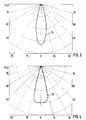
- FIG. 3 and 4 show a comparison of the light intensity distributions in a conventional luminaire with an ellipsoid reflector and a luminaire according to the invention according to FIG. 2.
- the light intensity distribution I 1 of a luminaire with a conventional ellipsoid reflector is a function of the beam angle in applied in the usual way. It can be seen from curve I 1 that the brightness drops sharply starting from a maximum at 0 ° to the side.
- a reflector surface according to the invention it is possible to have a reflector surface according to the invention to be faceted to give certain Light sources using a coiled wire have an aesthetically disruptive appearance of light and dark rings in the light spot to avoid.
- the shape does not necessarily have to be in relation to the central longitudinal plane of the reflector symmetrical be. Rather, the lower part of the reflector differ from the top to make an optimal Adaptation to the required lighting too to reach.
Landscapes
- Engineering & Computer Science (AREA)
- General Engineering & Computer Science (AREA)
- Optical Elements Other Than Lenses (AREA)
- Non-Portable Lighting Devices Or Systems Thereof (AREA)
Claims (1)
- Procédé pour l'engendrement d'une forme de réflecteur, dont la courbe de coupe (R), dans un plan contenant l'axe optique (1) de la lampe, n'est pas en forme de conique, caractérisé en ce que les points de la courbe de coupe de réflecteur (R) sont ainsi déterminés, qu'ils se trouvent chaque fois sur des rayons (2, 2'), qui sortent d'une origine (O) fixe en emplacement par rapport au réflecteur, et, pour chaque point (B, B') de la courbe de coupe de réflecteur (R), forment un autre angle (α,α') avec l'axe optique (1), et en ce que la position du point (B, B') sur le rayon (2, 2'), entre deux courbes de conique ((E1, E2 ; P ; E) enveloppant entre elles la courbe de coupe de réflecteur (R), est établie de telle sorte, que les espacements du point (B, B') des points de coupe (A, C) du rayon (2, 2') avec les courbes de conique (E1, E2 ; P, E) sont établis par un rapport d'espacement (k) préalloué.
Applications Claiming Priority (2)
| Application Number | Priority Date | Filing Date | Title |
|---|---|---|---|
| DE3919334A DE3919334A1 (de) | 1989-06-13 | 1989-06-13 | Reflektor fuer eine leuchte |
| DE3919334 | 1989-06-13 |
Publications (4)
| Publication Number | Publication Date |
|---|---|
| EP0402740A2 EP0402740A2 (fr) | 1990-12-19 |
| EP0402740A3 EP0402740A3 (fr) | 1991-12-11 |
| EP0402740B1 EP0402740B1 (fr) | 1995-01-11 |
| EP0402740B2 true EP0402740B2 (fr) | 1998-07-15 |
Family
ID=6382686
Family Applications (1)
| Application Number | Title | Priority Date | Filing Date |
|---|---|---|---|
| EP90110622A Expired - Lifetime EP0402740B2 (fr) | 1989-06-13 | 1990-06-05 | Procédé pour déterminer la forme d'un réflecteur pour lampe |
Country Status (4)
| Country | Link |
|---|---|
| US (1) | US5136491A (fr) |
| EP (1) | EP0402740B2 (fr) |
| JP (1) | JPH0738285B2 (fr) |
| DE (2) | DE3919334A1 (fr) |
Families Citing this family (40)
| Publication number | Priority date | Publication date | Assignee | Title |
|---|---|---|---|---|
| DE3919334A1 (de) * | 1989-06-13 | 1990-12-20 | Tetsuhiro Kano | Reflektor fuer eine leuchte |
| JP2831510B2 (ja) | 1991-03-14 | 1998-12-02 | 株式会社日立製作所 | 液晶表示素子及びこれを用いた液晶表示装置 |
| EP0519112B1 (fr) * | 1991-06-21 | 1996-03-13 | Tetsuhiro Kano | Réflecteur et procédé de génération de la forme du réflecteur |
| US5586013A (en) * | 1991-07-19 | 1996-12-17 | Minnesota Mining And Manufacturing Company | Nonimaging optical illumination system |
| US5289356A (en) * | 1991-07-19 | 1994-02-22 | Nioptics Corporation | Nonimaging optical illumination system |
| DE4307581A1 (de) * | 1993-03-10 | 1994-09-15 | Swarovski & Co | Lichteinkopplungsreflektor für Lichtleitsysteme |
| TW371319B (en) * | 1994-08-12 | 1999-10-01 | Matsushita Electric Industrial Co Ltd | Luminaire for interior lighting |
| JP3185125B2 (ja) * | 1994-10-28 | 2001-07-09 | 株式会社小糸製作所 | 車輌用灯具の反射鏡及びその形成方法 |
| JP3185126B2 (ja) * | 1994-10-28 | 2001-07-09 | 株式会社小糸製作所 | 車輌用灯具の反射鏡及びその形成方法 |
| US5515255A (en) * | 1994-11-14 | 1996-05-07 | Sterner Lighting Systems Incorporated | Lamp reflector |
| WO1996039313A1 (fr) * | 1995-06-06 | 1996-12-12 | Transmatic, Inc. | Systeme d'eclairage pour vehicules de transports en commun |
| US5961196A (en) * | 1996-07-26 | 1999-10-05 | Eastman Kodak Company | Flash device for dye transferring |
| US5934779A (en) * | 1996-07-26 | 1999-08-10 | Eastman Kodak Company | Reflector and a reflector/light source system |
| ATE316643T1 (de) * | 1996-10-18 | 2006-02-15 | Walter Wadey & Co Pty Ltd | Flutlicht- oder leuchten-aufbau |
| US6170962B1 (en) * | 1996-11-13 | 2001-01-09 | John Joseph Wordin | Dual compound reflector for fluorescent light fixtures |
| US6007220A (en) * | 1996-11-13 | 1999-12-28 | Innovative Engineering Solutions, Inc | Reflectors for fluorescent light fixtures |
| US6238075B1 (en) | 1996-12-17 | 2001-05-29 | Transmatic, Inc. | Lighting system for mass-transit vehicles |
| US5857758A (en) * | 1996-12-17 | 1999-01-12 | Transmatic, Inc. | Lighting system for mass-transit vehicles |
| DE69931466T2 (de) | 1998-01-26 | 2006-09-21 | Mag Instrument, Inc., Ontario | Stablampe |
| USD454651S1 (en) | 1998-01-26 | 2002-03-19 | Bison Sportslights, Inc. | Flashlight |
| US6354715B1 (en) | 1998-01-26 | 2002-03-12 | Bison Sportslights, Inc. | Flashlight |
| US6588917B1 (en) | 1998-06-18 | 2003-07-08 | Christopher Lee Halasz | Flashlight |
| DE19940207B4 (de) * | 1999-08-25 | 2005-07-14 | Tetsuhiro Kano | Reflektorsystem zum Führen von Licht unter kleinen Einfallswinkeln |
| US6953261B1 (en) * | 2000-02-25 | 2005-10-11 | North American Lighting, Inc. | Reflector apparatus for a tubular light source |
| US6323601B1 (en) * | 2000-09-11 | 2001-11-27 | Nordson Corporation | Reflector for an ultraviolet lamp system |
| US6559460B1 (en) | 2000-10-31 | 2003-05-06 | Nordson Corporation | Ultraviolet lamp system and methods |
| JP4070952B2 (ja) * | 2000-12-18 | 2008-04-02 | 株式会社小糸製作所 | 車両用灯具の反射鏡の反射面設計方法 |
| US6752515B2 (en) * | 2001-04-16 | 2004-06-22 | Cyberlux Corporation | Apparatus and methods for providing emergency lighting |
| US6739739B2 (en) * | 2002-06-13 | 2004-05-25 | Benq Corporation | Flash tube reflector |
| US6614028B1 (en) * | 2002-07-30 | 2003-09-02 | Fusion Uv Systems, Inc. | Apparatus for and method of treating a fluid |
| US6893140B2 (en) * | 2002-12-13 | 2005-05-17 | W. T. Storey, Inc. | Flashlight |
| DE10302930A1 (de) * | 2003-01-24 | 2004-07-29 | Patent-Treuhand-Gesellschaft für elektrische Glühlampen mbH | Reflektor und Reflektorlampe |
| US6854865B2 (en) * | 2003-02-12 | 2005-02-15 | W. T. Storey, Inc. | Reflector for light emitting objects |
| WO2004086455A2 (fr) * | 2003-03-28 | 2004-10-07 | Koninklijke Philips Electronics N.V. | Lampe halogene a double faisceau |
| CN1977127B (zh) * | 2004-03-30 | 2010-08-04 | 照明管理解决方案公司 | 用于改进的照明区域填充的设备和方法 |
| US7777198B2 (en) * | 2005-05-09 | 2010-08-17 | Applied Materials, Inc. | Apparatus and method for exposing a substrate to a rotating irradiance pattern of UV radiation |
| JP4308815B2 (ja) * | 2005-11-07 | 2009-08-05 | 株式会社フューチャービジョン | 面光源装置 |
| US7692171B2 (en) * | 2006-03-17 | 2010-04-06 | Andrzei Kaszuba | Apparatus and method for exposing a substrate to UV radiation using asymmetric reflectors |
| US7909595B2 (en) * | 2006-03-17 | 2011-03-22 | Applied Materials, Inc. | Apparatus and method for exposing a substrate to UV radiation using a reflector having both elliptical and parabolic reflective sections |
| WO2012138866A1 (fr) | 2011-04-08 | 2012-10-11 | Applied Materials, Inc. | Appareil et procédé pour traitement aux ultraviolets, traitement chimique et dépôt |
Family Cites Families (17)
| Publication number | Priority date | Publication date | Assignee | Title |
|---|---|---|---|---|
| DE217720C (fr) * | ||||
| FR454131A (fr) * | 1912-04-09 | 1913-06-26 | Alfred Brunn | Procédé pour la fabrication de mécanismes commutateurs électriques pour machines, appareils et instruments fonctionnant avec des cartons de dessin, avec des cartes jacquard, avec des plaques perforées ou avec d'autres équivalents |
| CH121919A (de) * | 1926-07-19 | 1927-08-01 | Berliner Spar Elektrizitaets G | Scheinwerfer für Beleuchtungszwecke. |
| DE1146825B (de) * | 1960-07-16 | 1963-04-11 | Braun Ag | Gleichmaessig ausleuchtender Reflektor, insbesondere fuer Blitzlichtgeraete |
| US3390262A (en) * | 1965-05-24 | 1968-06-25 | Sylvania Electric Prod | Multizone high power light reflector |
| US3398272A (en) * | 1965-12-03 | 1968-08-20 | William B. Elmer | Isoradiant energy reflecting |
| JPS456114Y1 (fr) * | 1966-01-29 | 1970-03-26 | ||
| FR1470102A (fr) * | 1966-02-25 | 1967-02-17 | Dispositif d'éclairage | |
| US4420801A (en) * | 1980-07-03 | 1983-12-13 | General Electric Company | Reflector lamp |
| US4356538A (en) * | 1980-08-04 | 1982-10-26 | Polaroid Corporation | Photographic lighting apparatus |
| NL8105535A (nl) * | 1981-12-09 | 1983-07-01 | Philips Nv | Reflektor. |
| US4481563A (en) * | 1982-05-10 | 1984-11-06 | Corning Glass Works | Automotive headlight having optics in the reflector |
| DE3340462C1 (de) * | 1983-11-09 | 1985-04-18 | Westfälische Metall Industrie KG Hueck & Co, 4780 Lippstadt | Abgeblendeter Fahrzeugscheinwerfer |
| JPS6186723U (fr) * | 1984-11-06 | 1986-06-06 | ||
| DE3527391A1 (de) * | 1985-07-31 | 1987-02-05 | Bosch Gmbh Robert | Nebelscheinwerfer fuer kraftfahrzeuge |
| DE3731232A1 (de) * | 1987-09-17 | 1989-03-30 | Bosch Gmbh Robert | Scheinwerfer fuer fahrzeuge, insbesondere scheinwerfer fuer kraftfahrzeuge |
| DE3919334A1 (de) * | 1989-06-13 | 1990-12-20 | Tetsuhiro Kano | Reflektor fuer eine leuchte |
-
1989
- 1989-06-13 DE DE3919334A patent/DE3919334A1/de not_active Withdrawn
-
1990
- 1990-06-05 DE DE59008220T patent/DE59008220D1/de not_active Expired - Fee Related
- 1990-06-05 EP EP90110622A patent/EP0402740B2/fr not_active Expired - Lifetime
- 1990-06-12 US US07/536,423 patent/US5136491A/en not_active Expired - Fee Related
- 1990-06-13 JP JP2152546A patent/JPH0738285B2/ja not_active Expired - Fee Related
Also Published As
| Publication number | Publication date |
|---|---|
| DE3919334A1 (de) | 1990-12-20 |
| JPH0738285B2 (ja) | 1995-04-26 |
| EP0402740A2 (fr) | 1990-12-19 |
| JPH0330204A (ja) | 1991-02-08 |
| EP0402740B1 (fr) | 1995-01-11 |
| EP0402740A3 (fr) | 1991-12-11 |
| DE59008220D1 (de) | 1995-02-23 |
| US5136491A (en) | 1992-08-04 |
Similar Documents
| Publication | Publication Date | Title |
|---|---|---|
| EP0402740B1 (fr) | Réflecteur pour lampe et procédé pour déterminer sa forme | |
| DE3027719C2 (fr) | ||
| DE3202080C2 (de) | Beleuchtungssystem für Endoskope | |
| DE69608044T2 (de) | Leuchte | |
| EP0519112A1 (fr) | Réflecteur et procédé de génération de la forme du réflecteur | |
| DE2238589B2 (de) | Lichtstreuende ebene Abdeckplatte für Deckenleuchten | |
| DE2826867A1 (de) | Leuchte | |
| DE1597945A1 (de) | Leuchte | |
| DE20206829U1 (de) | Leuchte, insbesondere Begrenzungsleuchte | |
| DE10011304A1 (de) | Leuchte mit inhomogener Lichtabstrahlung | |
| DE19961491B4 (de) | Innenraumleuchte mit Hohllichtleiter | |
| EP1059484A1 (fr) | Luminaire avec répartition de l'intensité lumineuse à faisceau large | |
| DE1201275B (de) | Scheinwerfer zum Ausleuchten einer recht-winkligen Flaeche | |
| EP2409075A1 (fr) | Réflecteur, agencement de source de lumière et appareil de projection | |
| EP3130843A1 (fr) | Dispositif de mélange et de conduction d'un rayonnement électromagnétique | |
| DE3150195A1 (de) | "reflektorlampe" | |
| DE3638669C2 (fr) | ||
| DE3125168C2 (de) | "Reflektor und daraus hergestellte Reflektorlampe" | |
| DE2614770A1 (de) | Reflektor mit rillen | |
| DE4204469C2 (de) | Blitzgerät | |
| EP2812629B1 (fr) | Projecteur à réflecteur | |
| EP1106916A2 (fr) | Luminaire comprenant des moyens réfractifs de protection et un réflecteur délimitant le faisceau lumineux | |
| DE102012209013B4 (de) | Optisches Element und ein Leuchtmodul | |
| DE2229011A1 (de) | Lichtstreuplatte für Leuchtstoffröhren | |
| DE1010024B (de) | Leuchte, insbesondere Signalleuchte fuer Kraftfahrzeuge |
Legal Events
| Date | Code | Title | Description |
|---|---|---|---|
| PUAI | Public reference made under article 153(3) epc to a published international application that has entered the european phase |
Free format text: ORIGINAL CODE: 0009012 |
|
| AK | Designated contracting states |
Kind code of ref document: A2 Designated state(s): DE FR GB IT NL |
|
| PUAL | Search report despatched |
Free format text: ORIGINAL CODE: 0009013 |
|
| AK | Designated contracting states |
Kind code of ref document: A3 Designated state(s): DE FR GB IT NL |
|
| 17P | Request for examination filed |
Effective date: 19920124 |
|
| 17Q | First examination report despatched |
Effective date: 19930521 |
|
| GRAA | (expected) grant |
Free format text: ORIGINAL CODE: 0009210 |
|
| AK | Designated contracting states |
Kind code of ref document: B1 Designated state(s): DE FR GB IT NL |
|
| PG25 | Lapsed in a contracting state [announced via postgrant information from national office to epo] |
Ref country code: NL Free format text: LAPSE BECAUSE OF FAILURE TO SUBMIT A TRANSLATION OF THE DESCRIPTION OR TO PAY THE FEE WITHIN THE PRESCRIBED TIME-LIMIT Effective date: 19950111 |
|
| ITF | It: translation for a ep patent filed | ||
| GBT | Gb: translation of ep patent filed (gb section 77(6)(a)/1977) |
Effective date: 19950119 |
|
| REF | Corresponds to: |
Ref document number: 59008220 Country of ref document: DE Date of ref document: 19950223 |
|
| ET | Fr: translation filed | ||
| PLBI | Opposition filed |
Free format text: ORIGINAL CODE: 0009260 |
|
| PLAB | Opposition data, opponent's data or that of the opponent's representative modified |
Free format text: ORIGINAL CODE: 0009299OPPO |
|
| 26 | Opposition filed |
Opponent name: KIRCHHOFF, MANFRED TECHNISCHE BERATUNG Effective date: 19951010 |
|
| R26 | Opposition filed (corrected) |
Opponent name: MANFRED KIRCHHOFF TECHNISCHE BERATUNG Effective date: 19951010 |
|
| NLR1 | Nl: opposition has been filed with the epo |
Opponent name: MANFRED KIRCHHOFF TECHNISCHE BERATUNG Opponent name: KIRCHHOFF, MANFRED TECHNISCHE BERATUNG |
|
| PLBF | Reply of patent proprietor to notice(s) of opposition |
Free format text: ORIGINAL CODE: EPIDOS OBSO |
|
| PGFP | Annual fee paid to national office [announced via postgrant information from national office to epo] |
Ref country code: NL Payment date: 19970630 Year of fee payment: 8 |
|
| PLAW | Interlocutory decision in opposition |
Free format text: ORIGINAL CODE: EPIDOS IDOP |
|
| PLAW | Interlocutory decision in opposition |
Free format text: ORIGINAL CODE: EPIDOS IDOP |
|
| PUAH | Patent maintained in amended form |
Free format text: ORIGINAL CODE: 0009272 |
|
| STAA | Information on the status of an ep patent application or granted ep patent |
Free format text: STATUS: PATENT MAINTAINED AS AMENDED |
|
| ITF | It: translation for a ep patent filed | ||
| 27A | Patent maintained in amended form |
Effective date: 19980715 |
|
| AK | Designated contracting states |
Kind code of ref document: B2 Designated state(s): DE FR GB IT NL |
|
| GBTA | Gb: translation of amended ep patent filed (gb section 77(6)(b)/1977) | ||
| NLR2 | Nl: decision of opposition | ||
| ET3 | Fr: translation filed ** decision concerning opposition | ||
| NLV1 | Nl: lapsed or annulled due to failure to fulfill the requirements of art. 29p and 29m of the patents act | ||
| PGFP | Annual fee paid to national office [announced via postgrant information from national office to epo] |
Ref country code: GB Payment date: 20000526 Year of fee payment: 11 |
|
| PGFP | Annual fee paid to national office [announced via postgrant information from national office to epo] |
Ref country code: FR Payment date: 20000530 Year of fee payment: 11 |
|
| PG25 | Lapsed in a contracting state [announced via postgrant information from national office to epo] |
Ref country code: GB Free format text: LAPSE BECAUSE OF NON-PAYMENT OF DUE FEES Effective date: 20010605 |
|
| GBPC | Gb: european patent ceased through non-payment of renewal fee |
Effective date: 20010605 |
|
| PG25 | Lapsed in a contracting state [announced via postgrant information from national office to epo] |
Ref country code: FR Free format text: LAPSE BECAUSE OF NON-PAYMENT OF DUE FEES Effective date: 20020228 |
|
| PG25 | Lapsed in a contracting state [announced via postgrant information from national office to epo] |
Ref country code: IT Free format text: LAPSE BECAUSE OF NON-PAYMENT OF DUE FEES;WARNING: LAPSES OF ITALIAN PATENTS WITH EFFECTIVE DATE BEFORE 2007 MAY HAVE OCCURRED AT ANY TIME BEFORE 2007. THE CORRECT EFFECTIVE DATE MAY BE DIFFERENT FROM THE ONE RECORDED. Effective date: 20050605 |
|
| PGFP | Annual fee paid to national office [announced via postgrant information from national office to epo] |
Ref country code: DE Payment date: 20080626 Year of fee payment: 19 |
|
| PG25 | Lapsed in a contracting state [announced via postgrant information from national office to epo] |
Ref country code: DE Free format text: LAPSE BECAUSE OF NON-PAYMENT OF DUE FEES Effective date: 20100101 |