EP0402779A2 - Procédé et dispositif de détermination de structures de surfaces - Google Patents
Procédé et dispositif de détermination de structures de surfaces Download PDFInfo
- Publication number
- EP0402779A2 EP0402779A2 EP90110848A EP90110848A EP0402779A2 EP 0402779 A2 EP0402779 A2 EP 0402779A2 EP 90110848 A EP90110848 A EP 90110848A EP 90110848 A EP90110848 A EP 90110848A EP 0402779 A2 EP0402779 A2 EP 0402779A2
- Authority
- EP
- European Patent Office
- Prior art keywords
- transmitter
- receiver
- waves
- marked
- ultrasonic
- Prior art date
- Legal status (The legal status is an assumption and is not a legal conclusion. Google has not performed a legal analysis and makes no representation as to the accuracy of the status listed.)
- Granted
Links
Images


Classifications
-
- A—HUMAN NECESSITIES
- A61—MEDICAL OR VETERINARY SCIENCE; HYGIENE
- A61B—DIAGNOSIS; SURGERY; IDENTIFICATION
- A61B5/00—Measuring for diagnostic purposes; Identification of persons
- A61B5/117—Identification of persons
- A61B5/1171—Identification of persons based on the shapes or appearances of their bodies or parts thereof
- A61B5/1172—Identification of persons based on the shapes or appearances of their bodies or parts thereof using fingerprinting
-
- G—PHYSICS
- G01—MEASURING; TESTING
- G01N—INVESTIGATING OR ANALYSING MATERIALS BY DETERMINING THEIR CHEMICAL OR PHYSICAL PROPERTIES
- G01N29/00—Investigating or analysing materials by the use of ultrasonic, sonic or infrasonic waves; Visualisation of the interior of objects by transmitting ultrasonic or sonic waves through the object
- G01N29/04—Analysing solids
- G01N29/041—Analysing solids on the surface of the material, e.g. using Lamb, Rayleigh or shear waves
-
- G—PHYSICS
- G01—MEASURING; TESTING
- G01N—INVESTIGATING OR ANALYSING MATERIALS BY DETERMINING THEIR CHEMICAL OR PHYSICAL PROPERTIES
- G01N29/00—Investigating or analysing materials by the use of ultrasonic, sonic or infrasonic waves; Visualisation of the interior of objects by transmitting ultrasonic or sonic waves through the object
- G01N29/34—Generating the ultrasonic, sonic or infrasonic waves, e.g. electronic circuits specially adapted therefor
- G01N29/341—Generating the ultrasonic, sonic or infrasonic waves, e.g. electronic circuits specially adapted therefor with time characteristics
- G01N29/345—Generating the ultrasonic, sonic or infrasonic waves, e.g. electronic circuits specially adapted therefor with time characteristics continuous waves
-
- G—PHYSICS
- G01—MEASURING; TESTING
- G01N—INVESTIGATING OR ANALYSING MATERIALS BY DETERMINING THEIR CHEMICAL OR PHYSICAL PROPERTIES
- G01N29/00—Investigating or analysing materials by the use of ultrasonic, sonic or infrasonic waves; Visualisation of the interior of objects by transmitting ultrasonic or sonic waves through the object
- G01N29/34—Generating the ultrasonic, sonic or infrasonic waves, e.g. electronic circuits specially adapted therefor
- G01N29/348—Generating the ultrasonic, sonic or infrasonic waves, e.g. electronic circuits specially adapted therefor with frequency characteristics, e.g. single frequency signals, chirp signals
-
- G—PHYSICS
- G01—MEASURING; TESTING
- G01S—RADIO DIRECTION-FINDING; RADIO NAVIGATION; DETERMINING DISTANCE OR VELOCITY BY USE OF RADIO WAVES; LOCATING OR PRESENCE-DETECTING BY USE OF THE REFLECTION OR RERADIATION OF RADIO WAVES; ANALOGOUS ARRANGEMENTS USING OTHER WAVES
- G01S15/00—Systems using the reflection or reradiation of acoustic waves, e.g. sonar systems
- G01S15/88—Sonar systems specially adapted for specific applications
- G01S15/89—Sonar systems specially adapted for specific applications for mapping or imaging
- G01S15/8906—Short-range imaging systems; Acoustic microscope systems using pulse-echo techniques
- G01S15/8909—Short-range imaging systems; Acoustic microscope systems using pulse-echo techniques using a static transducer configuration
- G01S15/8913—Short-range imaging systems; Acoustic microscope systems using pulse-echo techniques using a static transducer configuration using separate transducers for transmission and reception
-
- G—PHYSICS
- G06—COMPUTING OR CALCULATING; COUNTING
- G06V—IMAGE OR VIDEO RECOGNITION OR UNDERSTANDING
- G06V40/00—Recognition of biometric, human-related or animal-related patterns in image or video data
- G06V40/10—Human or animal bodies, e.g. vehicle occupants or pedestrians; Body parts, e.g. hands
- G06V40/12—Fingerprints or palmprints
- G06V40/13—Sensors therefor
- G06V40/1306—Sensors therefor non-optical, e.g. ultrasonic or capacitive sensing
-
- G—PHYSICS
- G01—MEASURING; TESTING
- G01N—INVESTIGATING OR ANALYSING MATERIALS BY DETERMINING THEIR CHEMICAL OR PHYSICAL PROPERTIES
- G01N2291/00—Indexing codes associated with group G01N29/00
- G01N2291/01—Indexing codes associated with the measuring variable
- G01N2291/012—Phase angle
-
- G—PHYSICS
- G01—MEASURING; TESTING
- G01N—INVESTIGATING OR ANALYSING MATERIALS BY DETERMINING THEIR CHEMICAL OR PHYSICAL PROPERTIES
- G01N2291/00—Indexing codes associated with group G01N29/00
- G01N2291/01—Indexing codes associated with the measuring variable
- G01N2291/015—Attenuation, scattering
-
- G—PHYSICS
- G01—MEASURING; TESTING
- G01N—INVESTIGATING OR ANALYSING MATERIALS BY DETERMINING THEIR CHEMICAL OR PHYSICAL PROPERTIES
- G01N2291/00—Indexing codes associated with group G01N29/00
- G01N2291/02—Indexing codes associated with the analysed material
- G01N2291/028—Material parameters
- G01N2291/0289—Internal structure, e.g. defects, grain size, texture
-
- G—PHYSICS
- G01—MEASURING; TESTING
- G01N—INVESTIGATING OR ANALYSING MATERIALS BY DETERMINING THEIR CHEMICAL OR PHYSICAL PROPERTIES
- G01N2291/00—Indexing codes associated with group G01N29/00
- G01N2291/04—Wave modes and trajectories
- G01N2291/042—Wave modes
- G01N2291/0425—Parallel to the surface, e.g. creep waves
-
- G—PHYSICS
- G01—MEASURING; TESTING
- G01N—INVESTIGATING OR ANALYSING MATERIALS BY DETERMINING THEIR CHEMICAL OR PHYSICAL PROPERTIES
- G01N2291/00—Indexing codes associated with group G01N29/00
- G01N2291/04—Wave modes and trajectories
- G01N2291/044—Internal reflections (echoes), e.g. on walls or defects
-
- G—PHYSICS
- G01—MEASURING; TESTING
- G01N—INVESTIGATING OR ANALYSING MATERIALS BY DETERMINING THEIR CHEMICAL OR PHYSICAL PROPERTIES
- G01N2291/00—Indexing codes associated with group G01N29/00
- G01N2291/10—Number of transducers
- G01N2291/102—Number of transducers one emitter, one receiver
Definitions
- the invention relates to a method and a device for the determination of surface structures and also of near-surface structures of objects.
- the methods known in optics only allow a determination of the surface condition, but not the determination of the structures located close to the surface. This fact can lead to incorrect determinations, since the surface structure is easily exposed to external influences, whether wanted or unwanted. Identification determinations after surface changes can no longer be carried out.
- the invention has set itself the task of not only determining the surface condition, but at the same time also the structure below the surface to a depth of approximately one wavelength.
- the object lying on a flat or curved surface is sonicated by a solid or a body filled with liquid with ultrasound waves, and the waves scattered and reflected by the sonication on the object are received by a receiver, the wavelengths of the ultrasound waves reflecting the structure of the object are adjusted.
- the intensity of the backscattered and reflected waves can determine the nature of the surface and the structure in the depth of approximately one wavelength, since the uneven density of the structure influences the scattering and reflection. It depends on the wavelength which influence the depth structure has. Therefore, according to the invention, the wavelengths of the ultrasonic waves are dimensioned such that they are approximately the same or approximately up to ten times shorter than the minimum or maximum Period length resulting from the spatial frequency spectrum of the object.
- the spatial frequency spectrum of each object describes this using frequencies and is calculated using the Fourier analysis.
- the inner structure of the surface of the object to be examined is a phase and / or amplitude structure.
- the phase structure which causes the wave to shift over time, causes asymmetrical backscattering.
- the transmitter of the ultrasonic waves and also the receiver of the scattered and reflected waves can be arranged separately from one another; however, a single ultrasound transducer can also be used, since because of the reciprocity of many conversion effects, ultrasound transducers can be used as transmitters and receivers.
- Ultrasonic transducers are selected that emit plane, spherical or only slightly different waves. Disk-shaped transmitters and receivers have proven to be particularly advantageous. The latter transmitters can be made of piezoceramic. Such transmitters emit waves running parallel to the surface of the transmitter, and the receiver is only sensitive to waves whose fronts run parallel to its surface. In this way, the receiver directly receives a Fourier transformation, which is based on the propulsion of the waves.
- Every parameter such as phase, amplitude or intensity can be taken from the Fourier transformation.
- the scatter and intensity of the backscattered waves in the different directions vary. Measuring units such as numbers, colors or other indicators can be assigned to the individual intensity values. By a such assignment are obtained in the evaluation of the backscattered waves images that are easily comparable. Particularly when assigning a color scale to the different intensity values, images can be generated that impressively reflect the examined object.
- the waves can also have other shapes which are produced by appropriately shaped transducers or lenses.
- a cylindrical shape of the shafts or shafts with two radii of curvature perpendicular to each other can also be used.
- the transmitter and receiver or generally the ultrasound transducer, which converts waves into signals or vice versa, can be arranged to be movable and search the object for certain or all angles. In this way, there is information at each position of the transducer due to the different scatter and reflection, the large amount of information ensuring a very precise picture of the surface quality and the structure close to the surface.
- several permanently mounted transmitters and receivers or ultrasonic transducers can also be provided, which are equipped with flat or curved surfaces. It has been shown that a suitable material for the transmitter, receiver or transducer is piezoceramic.
- the transmitter or transducer can either continuously send waves to the object or only send wave pulses. In the latter case, the transmitter is controlled by a pulse generator.
- the structure of the surface and the structure close to the surface can be examined and the properties can be stored in the form of information.
- This information can be compared with other stored data or can be represented by means of Fourier analysis methods by means of reconstruction.
- the transmitter or converter is excited by a frequency transmitter via a switch and, if appropriate, an amplifier. In the event that only wave pulses are to be applied to the object, the aforementioned switch is pulse-controlled.
- the waves reflected and scattered by the object are picked up by the receiver or transducer, which provides the information about the intensity and / or phase of the backscattering and the reflection via a detector, possibly also an amplifier, and a time control, which is possibly coordinated with the pulse generator Computer enters for analysis and recording.
- the method described is particularly suitable for the examination of objects such as fingertips, documents, maps, etc.
- the method enables that for the first time not only the pure surface condition, but also the structures near the surface can be determined by the penetration of the ultrasonic waves, which the identification of investigated material significantly improved and also simplified.
- the structure to be examined can be identified with little data and counterfeits can be excluded.
- the inventive method is also independent of displacement, provided that the shaft is flat, which saves the effort of positioning the object. Only the rotation of the structure may have to be compensated for.
- the determination of the density differences in accordance with the method according to the invention makes it very difficult, if not impossible, to forge the structure of the object to be examined, since density differences of the structures are considerably more difficult to manipulate than surface structures.
- the device shows a schematic representation of the device for carrying out the above-described method, which is used to determine surface structures including the structure near the surface.
- the device consists of a closed box 1, which is filled with a liquid medium, for example water.
- the underside of the box has a support surface 2 against which the object to be examined and determined is pressed.
- the contact surface 2 is made of plastic, for example.
- a fingertip 3 is shown as an object in the exemplary embodiment.
- any other object can also be used for the determination, e.g. crystalline plates, old writings, textile materials, etc.
- the transmitter 4 and the receiver 5 which are disc-shaped and made of the same material, preferably made of piezoceramic.
- the transmitter and the receiver are arranged next to one another on a common carrier 6 which moves along a curve in the box 1.
- the carrier 6 is guided according to the movement trajectory and is driven by a motor.
- the carrier 6 is adapted to the curve traveled.
- the family of wave fronts emitted by the transmitter 4 are denoted by 9, the wave fronts scattered back to the receiver by 10.
- the carrier moves on the trajectory 8 and thus captures the fingertip 3 from all sides and thus determines its spatial frequency spectrum.
- a fingerprint can be compared to the structure of a grid (parallel lines), since the print consists only of lines that clump in different directions and practically only one frequency occurs with grid structures.
- a fingertip transformed into a frequency spectrum results in a fairly simple structure that is at least considerably simpler than the fingerprint itself.
- FIG. 2 A possible circuit diagram is shown in FIG. 2, which generates the ultrasonic waves on the one hand and evaluates the backscattered waves and carries out time coordination.
- An ultrasonic generator 12 feeds the transmitter 4 via a switch 13 and an amplifier 14.
- the control unit 15 coordinates the correct chronological sequence of the signals.
- the signals received by the receiver are fed via an amplifier 16, a detector 17 and the evaluation device 18 which is coupled to the control device 15.
- the device 18 forwards the digital information of the determined signals to a computer.
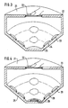
- the closed box 20 has the support surface 22 on its top 21.
- the box 20 has a circular cross section, and the transmitters 23 and the receivers 24 are arranged in a circle on floor parts (25) which run obliquely towards the center.
- the box 20 can optionally be filled with a solid or liquid medium. Filling the box with liquid or a solid substance is essential to dampen the sound waves.
- the transmitter 23 and the receiver 24 are connected to one another via the same circuit diagram as shown in FIG. 2.
- the individual transmitters and receivers are connected one after the other and coordinated in time.
- the embodiment according to FIG. 4 differs from the embodiment according to FIG. 3 only in that the transmitter 28 is arranged in the middle of the floor and the receivers 29 are arranged in two circles on the inclined floor parts.
- the surface and the structures close to the surface can be determined without problems.
- the respective choice of the device depends on the object and the degree of accuracy required.
Landscapes
- Physics & Mathematics (AREA)
- Engineering & Computer Science (AREA)
- Health & Medical Sciences (AREA)
- Life Sciences & Earth Sciences (AREA)
- General Physics & Mathematics (AREA)
- General Health & Medical Sciences (AREA)
- Pathology (AREA)
- Remote Sensing (AREA)
- Immunology (AREA)
- Radar, Positioning & Navigation (AREA)
- Biochemistry (AREA)
- Analytical Chemistry (AREA)
- Acoustics & Sound (AREA)
- Chemical & Material Sciences (AREA)
- Heart & Thoracic Surgery (AREA)
- Biomedical Technology (AREA)
- Public Health (AREA)
- Animal Behavior & Ethology (AREA)
- Surgery (AREA)
- Molecular Biology (AREA)
- Medical Informatics (AREA)
- Veterinary Medicine (AREA)
- Biophysics (AREA)
- Computer Networks & Wireless Communication (AREA)
- Human Computer Interaction (AREA)
- Multimedia (AREA)
- Theoretical Computer Science (AREA)
- Investigating Or Analyzing Materials By The Use Of Ultrasonic Waves (AREA)
- Length Measuring Devices Characterised By Use Of Acoustic Means (AREA)
Applications Claiming Priority (4)
| Application Number | Priority Date | Filing Date | Title |
|---|---|---|---|
| DE3919159 | 1989-06-12 | ||
| DE3919159 | 1989-06-12 | ||
| DE4016105A DE4016105B4 (de) | 1989-06-12 | 1990-05-18 | Verfahren und Vorrichtung zur Erfassung von Oberflächenstrukturen |
| DE4016105 | 1990-05-18 |
Publications (3)
| Publication Number | Publication Date |
|---|---|
| EP0402779A2 true EP0402779A2 (fr) | 1990-12-19 |
| EP0402779A3 EP0402779A3 (fr) | 1992-10-28 |
| EP0402779B1 EP0402779B1 (fr) | 2005-03-09 |
Family
ID=25881860
Family Applications (1)
| Application Number | Title | Priority Date | Filing Date |
|---|---|---|---|
| EP90110848A Expired - Lifetime EP0402779B1 (fr) | 1989-06-12 | 1990-06-08 | Procédé et dispositif de détermination de structures de surfaces |
Country Status (3)
| Country | Link |
|---|---|
| EP (1) | EP0402779B1 (fr) |
| JP (1) | JPH03103763A (fr) |
| AT (1) | ATE290339T1 (fr) |
Cited By (3)
| Publication number | Priority date | Publication date | Assignee | Title |
|---|---|---|---|---|
| WO1994001043A1 (fr) * | 1992-07-08 | 1994-01-20 | Stockburger H | Procede et dispositif d'identification d'objets a controler |
| WO1998008438A1 (fr) | 1996-08-28 | 1998-03-05 | Siemens Aktiengesellschaft | Procede et dispositif pour l'identification de personnes |
| WO2002037402A1 (fr) * | 2000-11-03 | 2002-05-10 | Stockburger, Andreas | Procede et dispositif pour identifier des objets a tester |
Family Cites Families (2)
| Publication number | Priority date | Publication date | Assignee | Title |
|---|---|---|---|---|
| US4385831A (en) * | 1980-09-22 | 1983-05-31 | Siemens Corporation | Device for investigation of a finger relief |
| DE3610397A1 (de) * | 1986-03-27 | 1987-10-01 | Storck Wolfgang | Verfahren zum erkennen eines fingerabdruckes |
-
1990
- 1990-06-08 AT AT90110848T patent/ATE290339T1/de not_active IP Right Cessation
- 1990-06-08 EP EP90110848A patent/EP0402779B1/fr not_active Expired - Lifetime
- 1990-06-12 JP JP2151774A patent/JPH03103763A/ja active Pending
Cited By (4)
| Publication number | Priority date | Publication date | Assignee | Title |
|---|---|---|---|---|
| WO1994001043A1 (fr) * | 1992-07-08 | 1994-01-20 | Stockburger H | Procede et dispositif d'identification d'objets a controler |
| US5551295A (en) * | 1992-07-08 | 1996-09-03 | Stockburger; Hermann | Method and apparatus using ultrasonic and light waves for identification of test specimens |
| WO1998008438A1 (fr) | 1996-08-28 | 1998-03-05 | Siemens Aktiengesellschaft | Procede et dispositif pour l'identification de personnes |
| WO2002037402A1 (fr) * | 2000-11-03 | 2002-05-10 | Stockburger, Andreas | Procede et dispositif pour identifier des objets a tester |
Also Published As
| Publication number | Publication date |
|---|---|
| EP0402779A3 (fr) | 1992-10-28 |
| JPH03103763A (ja) | 1991-04-30 |
| ATE290339T1 (de) | 2005-03-15 |
| EP0402779B1 (fr) | 2005-03-09 |
Similar Documents
| Publication | Publication Date | Title |
|---|---|---|
| DE69509882T2 (de) | Verfahren und gerät zur auswertung und charakterisierung von knocheneigenschaften | |
| DE69022562T2 (de) | Verbessertes Sonarsystem für Ozeanboden. | |
| DE3104014A1 (de) | "ultraschall-abtaster" | |
| EP1267177A1 (fr) | Procédé et dispositif pour la localisation d'objets dans l'espace | |
| DE4310390A1 (de) | Vorrichtung zur Erfassung von Oberflächenstrukturen | |
| DE2648589A1 (de) | Verfahren und einrichtung zum messen bzw. untersuchen der eigenschaften von koerperlichen teilen bzw. von materialien | |
| DE4391000C2 (de) | Transaxiales Kompressionsverfahren für die Schallgeschwindigkeitsberechnung | |
| DE2709725A1 (de) | Verfahren zur thermischen anregung von ultraschallwellen in lichtabsorbierenden oberflaechen von pruefstuecken | |
| WO1999004288A1 (fr) | Procede et dispositif pour la prise d'images ultrasoniques | |
| DE2260932A1 (de) | Verfahren und anordnung zur bestimmung von risstiefen bei der werkstoffpruefung mit ultraschall | |
| DE2245322C3 (de) | Verfahren zur zerstörungsfreien Messung der Schichtdicke einer durch eine oberflächliche Werkstoffstrukturveränderung betroffenen Schicht eines Körpers | |
| DE3787825T2 (de) | Verfahren zur Messung von Restspannungen im Stoff eines Prüfobjektes. | |
| DE2643126A1 (de) | Einrichtung zur untersuchung von objekten nach dem reflexionsprinzip | |
| EP0019793B1 (fr) | Procédé de détermination de la vitesse de matière en mouvement, notamment dans le corps et dispositif pour cette détermination et pour la visualisation de parties du corps | |
| DE19530116C2 (de) | Vorrichtung zum Darstellen von Schallaufzeiten | |
| DE112016006515T5 (de) | 2d-ultraschall-bildgebung mit doppler-bildgebung mit gepulsten wellen oder farbenfluss-bildgebung | |
| DE2652210A1 (de) | Verfahren und vorrichtung fuer die zerstoerungsfreie werkstoffpruefung mittels ultraschall | |
| DE68904613T2 (de) | Verfahren zur analyse und auswertung der ergebnisse einer ultraschalluntersuchung. | |
| DE4016105B4 (de) | Verfahren und Vorrichtung zur Erfassung von Oberflächenstrukturen | |
| DE2441768C2 (de) | Ultraschall-Impuls-Laufzeitverfahren zur zerstörungsfreien Werkstoffprüfung und Vorrichtung zu seiner Ausführung | |
| EP0402779B1 (fr) | Procédé et dispositif de détermination de structures de surfaces | |
| DE3889252T2 (de) | Ultraschall-Echographiegerät mit mindestens einem, mit einem Zufallsphase-Schirm verbundenen, piezoelektrischen Wandler und Verfahren zur Untersuchung eines Mediums mittels eines solchen Echographiegerätes. | |
| DE1773587A1 (de) | Werkstoffpruefgeraet | |
| DE4022152C2 (fr) | ||
| DE2345709C2 (de) | Querultraschallwandler |
Legal Events
| Date | Code | Title | Description |
|---|---|---|---|
| PUAI | Public reference made under article 153(3) epc to a published international application that has entered the european phase |
Free format text: ORIGINAL CODE: 0009012 |
|
| AK | Designated contracting states |
Kind code of ref document: A2 Designated state(s): AT BE CH DE DK ES FR GB GR IT LI LU NL SE |
|
| PUAL | Search report despatched |
Free format text: ORIGINAL CODE: 0009013 |
|
| AK | Designated contracting states |
Kind code of ref document: A3 Designated state(s): AT BE CH DE DK ES FR GB GR IT LI LU NL SE |
|
| 17P | Request for examination filed |
Effective date: 19930424 |
|
| 17Q | First examination report despatched |
Effective date: 19950203 |
|
| APAB | Appeal dossier modified |
Free format text: ORIGINAL CODE: EPIDOS NOAPE |
|
| APAB | Appeal dossier modified |
Free format text: ORIGINAL CODE: EPIDOS NOAPE |
|
| APAD | Appeal reference recorded |
Free format text: ORIGINAL CODE: EPIDOS REFNE |
|
| GRAH | Despatch of communication of intention to grant a patent |
Free format text: ORIGINAL CODE: EPIDOS IGRA |
|
| GRAS | Grant fee paid |
Free format text: ORIGINAL CODE: EPIDOSNIGR3 |
|
| RAP1 | Party data changed (applicant data changed or rights of an application transferred) |
Owner name: SONIDENT ANSTALT |
|
| GRAA | (expected) grant |
Free format text: ORIGINAL CODE: 0009210 |
|
| AK | Designated contracting states |
Kind code of ref document: B1 Designated state(s): AT BE CH DE DK ES FR GB GR IT LI LU NL SE |
|
| PG25 | Lapsed in a contracting state [announced via postgrant information from national office to epo] |
Ref country code: IT Free format text: LAPSE BECAUSE OF FAILURE TO SUBMIT A TRANSLATION OF THE DESCRIPTION OR TO PAY THE FEE WITHIN THE PRE;WARNING: LAPSES OF ITALIAN PATENTS WITH EFFECTIVE DATE BEFORE 2007 MAY HAVE OCCURRED AT ANY TIME BEFORE 2007. THE CORRECT EFFECTIVE DATE MAY BE DIFFERENT FROM THE ONE RECORDED.SCRIBED TIME-LIMIT Effective date: 20050309 Ref country code: NL Free format text: LAPSE BECAUSE OF FAILURE TO SUBMIT A TRANSLATION OF THE DESCRIPTION OR TO PAY THE FEE WITHIN THE PRESCRIBED TIME-LIMIT Effective date: 20050309 Ref country code: GB Free format text: LAPSE BECAUSE OF FAILURE TO SUBMIT A TRANSLATION OF THE DESCRIPTION OR TO PAY THE FEE WITHIN THE PRESCRIBED TIME-LIMIT Effective date: 20050309 |
|
| REG | Reference to a national code |
Ref country code: GB Ref legal event code: FG4D Free format text: NOT ENGLISH |
|
| REG | Reference to a national code |
Ref country code: CH Ref legal event code: EP |
|
| REF | Corresponds to: |
Ref document number: 59010942 Country of ref document: DE Date of ref document: 20050414 Kind code of ref document: P |
|
| PG25 | Lapsed in a contracting state [announced via postgrant information from national office to epo] |
Ref country code: LU Free format text: LAPSE BECAUSE OF NON-PAYMENT OF DUE FEES Effective date: 20050608 Ref country code: AT Free format text: LAPSE BECAUSE OF NON-PAYMENT OF DUE FEES Effective date: 20050608 |
|
| PG25 | Lapsed in a contracting state [announced via postgrant information from national office to epo] |
Ref country code: DK Free format text: LAPSE BECAUSE OF FAILURE TO SUBMIT A TRANSLATION OF THE DESCRIPTION OR TO PAY THE FEE WITHIN THE PRESCRIBED TIME-LIMIT Effective date: 20050609 Ref country code: GR Free format text: LAPSE BECAUSE OF FAILURE TO SUBMIT A TRANSLATION OF THE DESCRIPTION OR TO PAY THE FEE WITHIN THE PRESCRIBED TIME-LIMIT Effective date: 20050609 |
|
| PG25 | Lapsed in a contracting state [announced via postgrant information from national office to epo] |
Ref country code: ES Free format text: LAPSE BECAUSE OF FAILURE TO SUBMIT A TRANSLATION OF THE DESCRIPTION OR TO PAY THE FEE WITHIN THE PRESCRIBED TIME-LIMIT Effective date: 20050620 |
|
| REG | Reference to a national code |
Ref country code: SE Ref legal event code: TRGR |
|
| PG25 | Lapsed in a contracting state [announced via postgrant information from national office to epo] |
Ref country code: BE Free format text: LAPSE BECAUSE OF NON-PAYMENT OF DUE FEES Effective date: 20050630 |
|
| NLV1 | Nl: lapsed or annulled due to failure to fulfill the requirements of art. 29p and 29m of the patents act | ||
| PGFP | Annual fee paid to national office [announced via postgrant information from national office to epo] |
Ref country code: DE Payment date: 20050905 Year of fee payment: 16 |
|
| PGFP | Annual fee paid to national office [announced via postgrant information from national office to epo] |
Ref country code: CH Payment date: 20050916 Year of fee payment: 16 |
|
| APAH | Appeal reference modified |
Free format text: ORIGINAL CODE: EPIDOSCREFNO |
|
| GBV | Gb: ep patent (uk) treated as always having been void in accordance with gb section 77(7)/1977 [no translation filed] |
Effective date: 20050309 |
|
| PGFP | Annual fee paid to national office [announced via postgrant information from national office to epo] |
Ref country code: FR Payment date: 20051128 Year of fee payment: 16 |
|
| PGFP | Annual fee paid to national office [announced via postgrant information from national office to epo] |
Ref country code: SE Payment date: 20051202 Year of fee payment: 16 |
|
| PLBE | No opposition filed within time limit |
Free format text: ORIGINAL CODE: 0009261 |
|
| STAA | Information on the status of an ep patent application or granted ep patent |
Free format text: STATUS: NO OPPOSITION FILED WITHIN TIME LIMIT |
|
| 26N | No opposition filed |
Effective date: 20051212 |
|
| ET | Fr: translation filed | ||
| PG25 | Lapsed in a contracting state [announced via postgrant information from national office to epo] |
Ref country code: SE Free format text: LAPSE BECAUSE OF NON-PAYMENT OF DUE FEES Effective date: 20060609 |
|
| PG25 | Lapsed in a contracting state [announced via postgrant information from national office to epo] |
Ref country code: LI Free format text: LAPSE BECAUSE OF NON-PAYMENT OF DUE FEES Effective date: 20060630 Ref country code: CH Free format text: LAPSE BECAUSE OF NON-PAYMENT OF DUE FEES Effective date: 20060630 |
|
| PG25 | Lapsed in a contracting state [announced via postgrant information from national office to epo] |
Ref country code: DE Free format text: LAPSE BECAUSE OF NON-PAYMENT OF DUE FEES Effective date: 20070103 |
|
| REG | Reference to a national code |
Ref country code: CH Ref legal event code: PL |
|
| EUG | Se: european patent has lapsed | ||
| REG | Reference to a national code |
Ref country code: FR Ref legal event code: ST Effective date: 20070228 |
|
| BERE | Be: lapsed |
Owner name: SONIDENT ANSTALT Effective date: 20050630 |
|
| PG25 | Lapsed in a contracting state [announced via postgrant information from national office to epo] |
Ref country code: FR Free format text: LAPSE BECAUSE OF NON-PAYMENT OF DUE FEES Effective date: 20060630 |