EP0403013A2 - Dispositif pour la fixation amovible d'un rouleau dans un châssis - Google Patents
Dispositif pour la fixation amovible d'un rouleau dans un châssis Download PDFInfo
- Publication number
- EP0403013A2 EP0403013A2 EP90201499A EP90201499A EP0403013A2 EP 0403013 A2 EP0403013 A2 EP 0403013A2 EP 90201499 A EP90201499 A EP 90201499A EP 90201499 A EP90201499 A EP 90201499A EP 0403013 A2 EP0403013 A2 EP 0403013A2
- Authority
- EP
- European Patent Office
- Prior art keywords
- bearing
- platen
- arrangement according
- bearing opening
- board
- Prior art date
- Legal status (The legal status is an assumption and is not a legal conclusion. Google has not performed a legal analysis and makes no representation as to the accuracy of the status listed.)
- Ceased
Links
Images


Classifications
-
- B—PERFORMING OPERATIONS; TRANSPORTING
- B41—PRINTING; LINING MACHINES; TYPEWRITERS; STAMPS
- B41J—TYPEWRITERS; SELECTIVE PRINTING MECHANISMS, i.e. MECHANISMS PRINTING OTHERWISE THAN FROM A FORME; CORRECTION OF TYPOGRAPHICAL ERRORS
- B41J29/00—Details of, or accessories for, typewriters or selective printing mechanisms not otherwise provided for
- B41J29/02—Framework
-
- B—PERFORMING OPERATIONS; TRANSPORTING
- B41—PRINTING; LINING MACHINES; TYPEWRITERS; STAMPS
- B41J—TYPEWRITERS; SELECTIVE PRINTING MECHANISMS, i.e. MECHANISMS PRINTING OTHERWISE THAN FROM A FORME; CORRECTION OF TYPOGRAPHICAL ERRORS
- B41J11/00—Devices or arrangements of selective printing mechanisms, e.g. ink-jet printers or thermal printers, for supporting or handling copy material in sheet or web form
- B41J11/02—Platens
- B41J11/04—Roller platens
Definitions
- the invention relates to an arrangement for releasably attaching a platen of a device such.
- An arrangement of the type mentioned is z. B. become known from DE-PS 32 10 024.
- the known design is a device for the releasable fastening of rods in support boards which have bearing openings open on one side.
- Bearing bushes are provided on both ends of the linkage, which are flattened on at least one side in accordance with a narrowed opening width of the bearing opening.
- the linkage with the flattened sides of the bearing bushes is pushed into the bearing openings, rotated and locked in place via a locking connection between the locking levers and the circuit boards.
- the linkage is thus positively secured in the circuit boards and can be removed from the circuit boards in the opposite way.
- the axial displacement of the boom is achieved by additional positive locking means.
- the paper web with the associated guide and transport elements is arranged deep down in the device.
- the print platen for the printhead i. H. the platen roller
- these boards also accommodate all other necessary guide and transport elements for paper movement and printhead movement.
- problems arise when the platen roller is replaced.
- the casing of the housing should not be removed, so that a solution in which the platen roller is pushed sideways through a side wall is ruled out. Another possibility is the removal and installation upwards. It should be noted, however, that the print head with its paper guide plate moves above the platen.
- the invention is therefore based on the object to design the platen and its storage so that the interchangeability is possible without tools and without removing a device cover.
- This object is achieved with an arrangement of the type mentioned in that the open bearing opening for receiving the one bearing journal is arranged in an inwardly angled part of the board and in that the other bearing journal is mounted in a closed bearing opening of the other board.
- the platen roller can be pushed with one end into the closed bearing opening and then locked at its other end by rotating the bearing bush on the locking lever on the board part.
- the disassembly of the platen roller takes place in reverse order, ie first the locking at the end with the open bearing opening is released, then the platen roller is moved out of the closed bearing opening by a longitudinal movement and then removed from the housing with a pivoting movement around the print head.
- This possibility of assembling and disassembling the platen roller by means of a pivoting movement results from the arrangement of a closed bearing opening on the one hand and an inwardly projecting open bearing opening on the other hand. This projecting bearing point enables easy assembly and disassembly and also easy locking and unlocking of the platen roller at this point.
- the open bearing opening and the bearing bush are designed in such a way that the open bearing opening has a narrowed entrance such that the bearing bush has a first region with a diameter adapted to the bearing opening and an outer flange and a second, inward-facing region with a Has input adapted diameter and that the locking lever is arranged in the border area of the two areas and a neck fitting through the narrowed entrance having.
- This design has the advantage that the platen roller can first be inserted into the open bearing opening with the smaller diameter area of the bearing bush.
- the platen roller can be pushed so far to the right that the other end engages in the right, closed bearing opening, the neck of the locking lever penetrating the narrowed entrance of the open bearing opening and the bearing bush now with its first, flanged outward diameter range in the adapted Bearing opening is. Then the bearing bush can be turned so far that its locking lever locks with the board part.
- the bearing bush mounted on the platen roller is thus held immovably in the open bearing opening, on one side by the outer flange and on the other side of the circuit board part by the latching lever locked on the circuit board part.
- the latching can, for. B. done by a nose and a trough, which can be arranged alternately either in the board part or the locking lever.
- the rotational movement of the bearing bush can be limited by a projection which, after completion of the rotation, bears against a bevelled edge of the board part, the stop and the latching being matched to one another. This simplifies the assembly of the platen roller.
- the angled board part to form the open bearing opening is preferably formed by cranking out of the side board. This makes a special component and a special effort for fastening unnecessary.
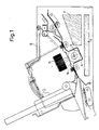
- the platen roller 13 has a housing 10 with side plates 11, 12, in which a platen roller 13 is mounted. With 14 a tub is designated, which is arranged around the platen and is used for guidance during assembly or disassembly. 15 is a movable print head along the platen with a paper guide plate 16 and 17 denotes electronic components.
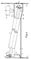
- the platen roller 13 has two journals 18, 19 for storage in an open bearing opening 20 and a closed bearing opening 21 (FIG. 4).
- the open bearing opening 20 is located in a part 22 of the plate 11 which is cranked inwards outwards.
- 23 denotes a bearing bush mounted on the bearing journal 18 by means of a clamping ring 24 (see also FIG. 8).
- FIG. 2 shows the platen roller, which is fixedly mounted in the boards 11 or 22 and 12, with the print head 15 and its paper guide plate 16.
- the print head 15 is moved over the platen roller 13 by a drive, not shown, in order to execute print commands.
- the print head 15 is first brought into the extreme right position shown.
- the left bearing point is then unlocked.
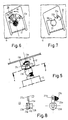
- the unlocking can be seen in FIGS. 5 and 6.
- the bearing bush 23 has a locking lever 25 with a narrow neck 25a, a locking lug 25b and a projection 25c.
- the dashed position of the bearing bush 23 in Fig. 6 shows the fixed position.
- the locking lever 25 is first deflected laterally, whereby the locking lug 25b is lifted out of a locking recess 22a of the board part 22.
- the locking lever 25 is then rotated in the direction of arrow 26 into the position shown in FIG. 6.
- the platen roller 13 can be moved in the direction of the arrow 27, the narrow neck 25a of the locking lever 25 being moved through the narrowed entrance 20a of the bearing opening 20.
- the position of the platen roller 13 after the end of this movement is shown in FIG. 3. 2, the bearing bush 23 with the diameter region 23a lies in the bearing opening 20.
- the bearing bush 23 with the tapered diameter region 23b lies in the bearing opening 23.
- the oblique transition region 23c serves to facilitate the Assembly.
- a gear 28 is out of engagement with a drive wheel 29.
- the journal 19 has left the bearing 21.
- the disassembly takes place around the print head 15 past the paper sign 16.
- the arranged on three sides around the platen 13 tray 14 has a guiding function and has a recess 14a in the right part, so that protruding parts, for. B. the gear 28, the assembly and disassembly do not hinder.
- the platen roller 13 falls down into the tub 14 after the bearing pin 19 has left the bearing 21 and can then be raised on the left-hand side in order to remove it from the printer according to FIG. 4.
- the right edge 13a of the platen roller 13 or the gear 28 slides over the bottom contour of the trough 14, so that the platen roller 13 is guided with the gear 28 around the print head 15.
- the tub 14 also prevents possible damage to the electronic parts 17 during assembly or disassembly.
- the platen roller 13 is installed in the reverse order.
- the platen roller 13 is inserted into the trough 14, the roller being guided exactly by the walls of the trough, so that when the bearing pin 19 is moved to the right, the bearing 21 is found automatically and exactly.
- Fig. 7 shows the view of the board part 22 from the direction 27 without an inserted platen.
- the bevel 22b serves to abut the projection 25c of the locking lever 25.
- Fig. 8 shows the bearing bush in two different views.
- An outer flange is designated by 23d.
- the board part 22 lies between the flange 23d and the locking lever 25 or the neck 25a.
Landscapes
- Handling Of Sheets (AREA)
- Accessory Devices And Overall Control Thereof (AREA)
Applications Claiming Priority (2)
| Application Number | Priority Date | Filing Date | Title |
|---|---|---|---|
| DE3919754A DE3919754A1 (de) | 1989-06-16 | 1989-06-16 | Anordnung zur loesbaren befestigung einer schreibwalze in platinen |
| DE3919754 | 1989-06-16 |
Publications (2)
| Publication Number | Publication Date |
|---|---|
| EP0403013A2 true EP0403013A2 (fr) | 1990-12-19 |
| EP0403013A3 EP0403013A3 (fr) | 1991-01-16 |
Family
ID=6382907
Family Applications (1)
| Application Number | Title | Priority Date | Filing Date |
|---|---|---|---|
| EP19900201499 Ceased EP0403013A3 (fr) | 1989-06-16 | 1990-06-11 | Dispositif pour la fixation amovible d'un rouleau dans un châssis |
Country Status (4)
| Country | Link |
|---|---|
| US (1) | US5044800A (fr) |
| EP (1) | EP0403013A3 (fr) |
| JP (1) | JPH0326565A (fr) |
| DE (1) | DE3919754A1 (fr) |
Families Citing this family (11)
| Publication number | Priority date | Publication date | Assignee | Title |
|---|---|---|---|---|
| JPH0674341U (ja) * | 1993-03-31 | 1994-10-21 | マックス株式会社 | マークチューブのための熱転写印刷機 |
| US6702282B2 (en) * | 1997-10-24 | 2004-03-09 | Fargo Electronics, Inc. | Card transport mechanism roller support |
| TWI248757B (en) * | 2004-07-05 | 2006-02-01 | Avision Inc | Automatic document feeder having a replaceable friction roller assembly |
| JP4376816B2 (ja) * | 2005-03-17 | 2009-12-02 | セイコーインスツル株式会社 | プラテンローラ保持構造および記録装置 |
| US20080194305A1 (en) * | 2007-02-12 | 2008-08-14 | Matousek Robert A | Bearing assembly and cleaning system in combine harvesters |
| DE102007030620A1 (de) * | 2007-07-02 | 2009-01-08 | Mettler-Toledo (Albstadt) Gmbh | Drucker |
| US8979407B2 (en) * | 2007-08-08 | 2015-03-17 | Zih Corp. | Platen assembly |
| JP5536480B2 (ja) * | 2010-02-02 | 2014-07-02 | セイコーインスツル株式会社 | プリンタ |
| JP2011168029A (ja) * | 2010-02-22 | 2011-09-01 | Seiko Instruments Inc | プリンタ |
| JP5935713B2 (ja) * | 2013-02-18 | 2016-06-15 | ブラザー工業株式会社 | 搬送装置及び画像記録装置 |
| DE202022001624U1 (de) * | 2022-02-28 | 2022-08-08 | Zehnder & Sommer Ag | Walzenvorschub mit Rohrwalze und vereinfachtem Ein-/Ausbau |
Family Cites Families (11)
| Publication number | Priority date | Publication date | Assignee | Title |
|---|---|---|---|---|
| DE322750C (de) * | 1920-07-07 | Hermann Wasem | Auswechselbare Schreibwalze | |
| US1523480A (en) * | 1921-12-13 | 1925-01-20 | Grandjean Marc | Removable articulated striker cylinder for stenographic and like machines |
| US2542868A (en) * | 1949-01-31 | 1951-02-20 | Royal Typewriter Co Inc | Detachable platen mounting for typewriting or like machines |
| US2880839A (en) * | 1957-05-06 | 1959-04-07 | Royal Mcbee Corp | Locking device for typewriters and like machines |
| DE2656303A1 (de) * | 1976-12-11 | 1978-06-15 | Hacklaender & Rolf Kg Haro Foe | Rollenbahn |
| DE2941172C2 (de) * | 1979-10-11 | 1982-09-09 | Triumph-Adler Aktiengesellschaft für Büro- und Informationstechnik, 8500 Nürnberg | Lagerteil, z.B. für die Achse einer Schreibwalze in Büromaschinen |
| IT8423457V0 (it) * | 1984-10-05 | 1984-10-05 | Siat Spa | Disposizione di montaggio di rulli, in trasportatori a rulli e rulliere in genere. |
| JPS61149381A (ja) * | 1984-12-25 | 1986-07-08 | Matsushita Electric Ind Co Ltd | プラテン支持装置 |
| JPS62174171A (ja) * | 1986-01-28 | 1987-07-30 | Ricoh Co Ltd | 印字装置 |
| JPS6368445U (fr) * | 1986-10-24 | 1988-05-09 | ||
| EP0306591A1 (fr) * | 1987-09-09 | 1989-03-15 | MANNESMANN Aktiengesellschaft | Dispositif de fixation pour arbres dans des machines de bureau notamment dans des imprimantes |
-
1989
- 1989-06-16 DE DE3919754A patent/DE3919754A1/de not_active Withdrawn
-
1990
- 1990-06-11 EP EP19900201499 patent/EP0403013A3/fr not_active Ceased
- 1990-06-13 US US07/537,559 patent/US5044800A/en not_active Expired - Fee Related
- 1990-06-15 JP JP2155608A patent/JPH0326565A/ja active Pending
Also Published As
| Publication number | Publication date |
|---|---|
| DE3919754A1 (de) | 1990-12-20 |
| EP0403013A3 (fr) | 1991-01-16 |
| JPH0326565A (ja) | 1991-02-05 |
| US5044800A (en) | 1991-09-03 |
Similar Documents
| Publication | Publication Date | Title |
|---|---|---|
| DE69106946T2 (de) | Thermozeilendrucker. | |
| DE3342894A1 (de) | Kassette fuer einen schreibkopf einer tintenschreibvorrichtung in einer schreibmaschine | |
| EP0403013A2 (fr) | Dispositif pour la fixation amovible d'un rouleau dans un châssis | |
| DE3210024C2 (de) | Vorrichtung zum lösbaren Befestigen von Gestängen in Stützplatinen | |
| DE2707643C3 (de) | Vorrichtung zum Spannen eines Drucktuches auf dem Zylinder einer Druckmaschine | |
| DE2512274C3 (de) | Vorrichtung zur Lagerung der Schreibwalze, der Papierabstreifleiste und des Andruckbügels einer Druckmaschine | |
| CH649038A5 (de) | Elektrische druckvorrichtung fuer eine schreibmaschine oder einen drucker. | |
| EP4097802B1 (fr) | Cadre de retenue pour une fiche de connexion, procédé, fiche de connexion et dispositif électronique | |
| DE2547481C3 (de) | Vorrichtung zum Befestigen und Spannen von biegsamen Druckplatten | |
| DE2756511A1 (de) | Verriegelungsvorrichtung fuer schachtabdeckungen von strasseneinsteigschaechten, bestehend aus einem fortnehmbaren deckel und einer feststehenden basis | |
| DE1775034B1 (de) | Loesbare nutfederverbindung zur halterung streifen und platten foermiger bauteile insbesondere fuer abstreichleisten an papiermaschinen | |
| EP0359957A2 (fr) | Presse à imprimer avec au moins un dispositif d'encrage à lame | |
| DE2628249A1 (de) | Biegevorrichtung fuer offset-druckplatten | |
| EP0741021B1 (fr) | Dispositif d'assemblage des dispositifs de serrage avec une traverse d'un cylindre de forme | |
| DE3347884A1 (de) | Befestigungsvorrichtung zum entfernbaren befestigen zweier werkstuecke miteinander | |
| DE3101648A1 (de) | Papiervorschubeinrichtung | |
| DE2618001C3 (de) | Baueinheit zur Führung eines Druckkopfes parallel zum Druckwiderlager in Buchungs- und Rechenmaschinen | |
| DE2855503A1 (de) | Einrichtung zum wechsel einer typenscheibe in einer schreib- o.ae. bueromaschine | |
| DE3138828C2 (de) | Farbbandkassette | |
| DE3149111C2 (de) | Halterung von Leit- und/oder Umlenkblechen in einem Entwicklungsgeät für fotografische Schichtträger | |
| DE3136209C2 (de) | Druckkopfeinstellvorrichtung | |
| DE20105075U1 (de) | Klauenschaltvorrichtung für ein Ratschenwerkzeug | |
| DE3401336C2 (fr) | ||
| EP0384443A1 (fr) | Automate à café | |
| DE3206292C2 (de) | Verriegelungsvorrichtung für einen abnehmbaren Sonnenschutz an einem Fahrzeugdach |
Legal Events
| Date | Code | Title | Description |
|---|---|---|---|
| PUAI | Public reference made under article 153(3) epc to a published international application that has entered the european phase |
Free format text: ORIGINAL CODE: 0009012 |
|
| PUAL | Search report despatched |
Free format text: ORIGINAL CODE: 0009013 |
|
| AK | Designated contracting states |
Kind code of ref document: A2 Designated state(s): DE FR GB IT SE |
|
| AK | Designated contracting states |
Kind code of ref document: A3 Designated state(s): DE FR GB IT SE |
|
| 17P | Request for examination filed |
Effective date: 19910711 |
|
| 17Q | First examination report despatched |
Effective date: 19930224 |
|
| STAA | Information on the status of an ep patent application or granted ep patent |
Free format text: STATUS: THE APPLICATION HAS BEEN REFUSED |
|
| 18R | Application refused |
Effective date: 19930819 |