EP0403171A1 - Dispositif distributeur de liquide - Google Patents
Dispositif distributeur de liquide Download PDFInfo
- Publication number
- EP0403171A1 EP0403171A1 EP90306258A EP90306258A EP0403171A1 EP 0403171 A1 EP0403171 A1 EP 0403171A1 EP 90306258 A EP90306258 A EP 90306258A EP 90306258 A EP90306258 A EP 90306258A EP 0403171 A1 EP0403171 A1 EP 0403171A1
- Authority
- EP
- European Patent Office
- Prior art keywords
- dispensing
- liquid
- chamber
- drinks
- liquid dispensing
- Prior art date
- Legal status (The legal status is an assumption and is not a legal conclusion. Google has not performed a legal analysis and makes no representation as to the accuracy of the status listed.)
- Withdrawn
Links
- 239000007788 liquid Substances 0.000 title claims abstract description 66
- 230000006854 communication Effects 0.000 claims abstract description 8
- 238000004891 communication Methods 0.000 claims abstract description 8
- 238000006073 displacement reaction Methods 0.000 claims description 11
- 235000015096 spirit Nutrition 0.000 claims description 9
- 238000012544 monitoring process Methods 0.000 claims description 3
- 238000013500 data storage Methods 0.000 claims description 2
- 230000000977 initiatory effect Effects 0.000 claims description 2
- 235000014101 wine Nutrition 0.000 claims description 2
- 239000000523 sample Substances 0.000 description 45
- 239000011521 glass Substances 0.000 description 21
- 239000012528 membrane Substances 0.000 description 8
- 230000006835 compression Effects 0.000 description 5
- 238000007906 compression Methods 0.000 description 5
- 238000010586 diagram Methods 0.000 description 4
- 230000002093 peripheral effect Effects 0.000 description 4
- 230000005484 gravity Effects 0.000 description 3
- 238000000034 method Methods 0.000 description 3
- 235000013532 brandy Nutrition 0.000 description 2
- 235000020047 vermouth Nutrition 0.000 description 2
- 230000000007 visual effect Effects 0.000 description 2
- 229910001369 Brass Inorganic materials 0.000 description 1
- 235000013334 alcoholic beverage Nutrition 0.000 description 1
- 230000007175 bidirectional communication Effects 0.000 description 1
- 230000000903 blocking effect Effects 0.000 description 1
- 239000010951 brass Substances 0.000 description 1
- 238000004140 cleaning Methods 0.000 description 1
- 238000012790 confirmation Methods 0.000 description 1
- 239000000470 constituent Substances 0.000 description 1
- 238000010276 construction Methods 0.000 description 1
- 230000008602 contraction Effects 0.000 description 1
- 238000013016 damping Methods 0.000 description 1
- 230000007423 decrease Effects 0.000 description 1
- 230000000994 depressogenic effect Effects 0.000 description 1
- 230000035622 drinking Effects 0.000 description 1
- 239000000428 dust Substances 0.000 description 1
- 238000009713 electroplating Methods 0.000 description 1
- 238000001704 evaporation Methods 0.000 description 1
- 230000008020 evaporation Effects 0.000 description 1
- 235000013305 food Nutrition 0.000 description 1
- 230000006870 function Effects 0.000 description 1
- 235000021189 garnishes Nutrition 0.000 description 1
- PCHJSUWPFVWCPO-UHFFFAOYSA-N gold Chemical compound [Au] PCHJSUWPFVWCPO-UHFFFAOYSA-N 0.000 description 1
- 239000010931 gold Substances 0.000 description 1
- 229910052737 gold Inorganic materials 0.000 description 1
- 238000005286 illumination Methods 0.000 description 1
- 239000000463 material Substances 0.000 description 1
- 239000000203 mixture Substances 0.000 description 1
- 230000003287 optical effect Effects 0.000 description 1
- 239000004033 plastic Substances 0.000 description 1
- 238000012545 processing Methods 0.000 description 1
- 230000000284 resting effect Effects 0.000 description 1
- 238000000926 separation method Methods 0.000 description 1
- 125000006850 spacer group Chemical group 0.000 description 1
- 229910001220 stainless steel Inorganic materials 0.000 description 1
- 239000010935 stainless steel Substances 0.000 description 1
- 238000003756 stirring Methods 0.000 description 1
- 238000012546 transfer Methods 0.000 description 1
Images


Classifications
-
- B—PERFORMING OPERATIONS; TRANSPORTING
- B67—OPENING, CLOSING OR CLEANING BOTTLES, JARS OR SIMILAR CONTAINERS; LIQUID HANDLING
- B67D—DISPENSING, DELIVERING OR TRANSFERRING LIQUIDS, NOT OTHERWISE PROVIDED FOR
- B67D3/00—Apparatus or devices for controlling flow of liquids under gravity from storage containers for dispensing purposes
- B67D3/0003—Apparatus or devices for controlling flow of liquids under gravity from storage containers for dispensing purposes provided with automatic fluid control means
-
- G—PHYSICS
- G07—CHECKING-DEVICES
- G07F—COIN-FREED OR LIKE APPARATUS
- G07F13/00—Coin-freed apparatus for controlling dispensing or fluids, semiliquids or granular material from reservoirs
- G07F13/02—Coin-freed apparatus for controlling dispensing or fluids, semiliquids or granular material from reservoirs by volume
Definitions
- the invention relates to liquid dispensing apparatus and relates particularly, but not exclusively, to apparatus for dispensing drinks in accurate measures.
- Optic a dispensing device known as an "Optic”
- Optic a dispensing device
- the bottle with the container attached is up-ended and attached to a support.
- the container fills through the inlet, the required measure being the volume of the container.
- a glass is pushed up against the outlet causing it to open and dispense the measure into the glass, at the same time the inlet being maintained shut.
- the outlet is shut and the inlet opens and the container is refilled under gravity from the bottle.
- this device is unhygienic due to the contact of the glass with the device and the accuracy is still not good, being officially given as -3% to +6% but in practice, particularly with rushed staff, often being worse. Also a considerable time is taken to dispense a double.
- Liquid dispensing apparatus of higher accuracy has been constructed but typically such apparatus involves means for precision metering of the liquid and is consequently expensive and unhygienic.
- a liquid dispensing apparatus comprising two liquid dispensing chambers defining therein a volume measure and each having an outlet, independent means for opening and closing each outlet, a prefill chamber, and means for filling the dispensing chambers with liquid from the prefill chamber, the dispensing chambers being in communication with the prefill chamber in such a way that liquid in excess of the predetermined measures overflows back to the prefill chamber, wherein sensor means are provided for determining the correct operation of the dispenser chamber outlets.
- the appartus includes indicator means which indicate when the apparatus is in the empty, error or ready condition.
- the filling means preferably comprises a displacement device which may be solenoid operated.
- the apparatus preferably comprises pressure sensitive switch means enabling or initiating a dispense cycle of the apparatus.
- the apparatus comprises switch means for independently opening the or each dispensing chamber outlet, whereafter the outlet or outlets is or are closed and the or each dispensing chamber is refilled from the prefill chamber.
- the outlet opening means is solenoid operated.
- the apparatus preferably comprises sensor means for determination of the liquid level in the prefill and dispensing chambers.
- one or more dispensing apparatus are included in a drinks dispensing unit comprising means for determining if the unit is level and means for monitoring and recording the volume of liquid dispensed, comprising a controller responsive to signals indicative of the liquid dispensed from the or each apparatus.
- the controller comprises means for intelligent communication with point-of-sale terminals, means for programme storage and means for data storage and distribution.
- one or more drinks dispensing units would be incorporated into overall stock recording drinks dispensing systems.
- the liquid dispensing apparatus is mounted in a secure cabinet access to which is gained by electronic release means.
- the electronic release means may take the form of a cash acceptor, be key operated or may include a credit card reader.
- the drinks dispensing apparatus may include a drinks selector related to a customer drink identification means.
- the drinks dispensing apparatus is capable of dispensing measured quantities of any liquid but is particularly applicable to the dispensing of spirits or wines.
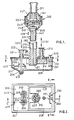
- a single prefill chamber 208 is provided for filling both dispensing chambers 201 and 202.
- the height of the weirs 200 (which separate the dispensing chambers from the prefill chamber and are circular in plan) define the required volume measures in the dispensing chambers 201, 202.
- the drink to be dispensed, spirits or the like, is supplied to the prefill chamber 208 through a feed pipe 210 which extends down into the prefill chamber to a level below that of the weirs; a distance of 10 mm below the level of the weirs has been found suitable.
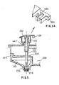
- the dispensing chambers 201, 202 are filled with liquid from the prefill chamber 208 by virtue of the displacing action of a solenoid 215 operating the device 214.
- the solenoid (not shown) operating the displacement device 214 is single acting in a downward direction, compression spring 213 providing the return, upward motion when the solenoid is de-energized.
- the outlets 204, 205 of the dispensing chambers 201, 202 are openable and closable by seals 219, 220.
- Each seal 219, 220 is operated by a respective solenoid 250, 251 which again is single acting in a downard direction, the return upward movement being provided by a respective compression spring 221 which acts against a cap 222 fixed to shaft 223 on which the respective seal 219, 220 is mounted (see also Fig. 5).
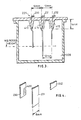
- a liquid sensor 225 is mounted in the prefill chamber 208.
- This sensor comprises three probes 230, 231 and 232 of which probe 231 is electrically common, 230 is an overmeasure sensor and 232 is an undermeasure sensor.
- the three probes are set at appropriate heights as required, preferred positions being 1.5 mm below the level of weirs 200 for probe 230, 15 mm below the weirs 200 for probe 231 and 7 mm above the level of the weirs for probe 232.
- the probes are checked by routing a 12V 6kH z signal through the probes and comparing the resistance between the probes with an external reference resistor typically set between 270 k Ohm and 370 k Ohm.
- a 6kH z signal is used for two reasons, the first being to prevent electroplating of the probes and the second to ensure conductivity, through the liquid. It has been found by experimentation that the mode of conduction through the liquid is ionic and not electronic, hence the range of resistances of spirits is vast ranging from sugar based spirits such as Rum (low) to white spirits such as Gin (high). This causes a problem in that that to detect high resistance spirits making a circuit by tracking between the probes.
- the tracking length denoted by xxxx in Fig. 3 is a minimum of 40 mm which is achieved by providing plastic housing extensions 415 (14 mm long minimum) and a probe contact housing dimension of 12 mm minimum. It has been found however that a probe spacing of 12 mm is too high to detect the high resistance spirits and it is therefore necessary to bend the probes nearer to each other such that they are a maximum of 10 mm apart. It also improves the conduction between the probe 231 and the probes 230, 232 if the probe 231 is further extended into the liquid, and that the probes are a minimum of 8 mm wide as shown in Fig. 4.
- the probes can be manufactured from a thin material (typically 0. 4 mm thick). Stainless steel has been found to be preferable but the probes could alternatively be gold plated brass, for example.
- a bottle adaptor 240 is provided.
- the structure of this adaptor will be apparent from Fig. 1.
- the adaptor comprises a rubber annulus 241 which can be compressed onto the neck of the bottle 211 by tightening a hand nut 260, the nut 260 being threadedly engaged with the lower body part 243 of the adaptor. Rotation of nut 260 relative to part 243 draws annular intermediate member 247 towards part 243 and insert 249 which is secured to part 243, thereby causing the compression of annulus 241.
- Part 243 is provided with O-ring seals 244 for air-tight engagement with the interior of the upper part of feed pipe 210.
- the adaptor is first pushed onto the bottle 211 and the hand nut 260 tightened to compress seal 241 which both grips and seals the bottleneck, following which the lower adaptor body part 243 is pushed into the pipe 210 to rest against internal shoulder 209.
- sensors 504, 505 are provided, such as slotted optical sensors co-operating with a flag 430 in the cap 222 connected to the seal shafts 223 (see Fig. 5A).
- Airway 440 is provided to aid the discharge of liquid from dispense chamber 201. This arrangement is duplicated for dispense chamber 202. The airway 440 is protected against the ingress of dust and blockage by the cap 222.
- buttons 217, 218 are provided.
- a dispense enabling switch 216 is provided that is sensitive to a glass 206 resting on it.
- the switch shown in Figs. 6 and 6A comprises an upper membrane 450 coated with a conductive ink 451 so as to act as an electrically shorting member, a lower membrane 455 coated with conductive ink 456 which acts as one side of a switch and further coated with conductive ink 457 (electrically insulated from 456) which acts as the other side of the switch 456 and 457 are schematically shown terminated at 475.
- the upper membrane 450 and the lower membrane 455 are separated around their periphery by spacer 460 which is in practise 09.010 inches thick.
- the membranes 450 and 455 are further kept apart by compression spring 465 which has a rate of approximately 0.025 N/mm.
- the switch 216 is sealed therefore vent 470 is provided to prevent hydraulic damping.
- Fig. 6 shows the switch 216 electrically open circuit, i.e. without a glass in position.
- a leak detector can be positioned between the dispensing chambers and the glass 226.
- a sensor 228 may be provided to check that a bottle is in position.
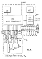
- Fig. 7 shows the electrical connections of the apparatus connected into an overall drink dispensing, monitoring and recording unit.
- Drink dispensing unit 300 comprises eight sets of dispensing apparatus or stations S1 to S8 as described i.e. with sixteen dispensing outlets. Only the connections for dispensing station S1 are shown, these being duplicated for the other seven stations.
- single measure button 217 is common to all the stations but each station has its own double measure button 218.
- Button 320 is provided to close down any of the eight dispensing stations and to reset a closed down station to bring it back into use.
- "Stock input" button 321 is merely for accounting purposes, to record when a drink has been dispensed but is not actually sold (e.g. if the operator demands in error a drink other than the one requested by the customer).
- "Empty” indicator light 255 is provided to give a visual indication that the bottle needs replacing.
- "Ready” indicator 310 is provided to give a visual indication that a glass is in position.
- "Error” indicator is provided to give an indication of a fault (dispense inhibited).
- the operation of all buttons, sensors and actuators is controlled by an integral micro control unit 234 powered by integral power supply 490.
- a commununications port 480 is provided to receive and transmit data in various serial protocols and data variable band rates.
- a tilt sensor 495 is provided to disable the unit 300 if the unit 300 is set out of level.
- the integral micro control unit also contains battery backed RAM for memory and ROM for operational software, means for electronically identifying the unit and means of changing that identification up to 16 times.
- An optional integral battery 497 can be provided to give sensor power failure back up.
- the apparatus may be operated as follows. When a new bottle 211, with adaptor 240 attached, is inserted into the apparatus, liquid from the bottle 211 flows down through the adaptor and feed pipe 210 to the prefill chamber 208. Flow continues until the liquid level in the prefill chamber is coincident with the bottom of the feed pipe 210.
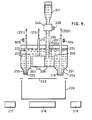
- the displacement device 214 (see Fig. 9) is operated to raise the liquid level above the weirs 200 and is held down for a predetermined time such as 3.0 secs. At the end of this time, the control unit 234 checks that the liquid level has reached and made the probe 232 for a predetermined time such as 1.5 seconds as a check that the dispensing chambers 201, 202 are fully charged. If liquid is present at probe 232 the controller checks probe 230, if no circuit is made at probe 230 then an "overmeasure probe open circuit" condition would be diagnosed and the error indicator 311 is illuminated. After these checks the displacement device 214 is retracted to allow the liquid level in the prefill chamber 208 to fall (see Fig.
- the controller After the displacement device 214 is retracted the controller, after a predetermined time, checks the probe 230 for the presence of liquid. If liquid is present at probe 230 a "displacement device stuck down" condition is diagnosed, the dispense inhibited and the error indicator 311 illuminated.
- a glass 206 When a drink is required a glass 206 must be placed on the dispense enabling switch to enable dispensing. This is acknowledged by the illumination of the ready indicator 310.
- the controller 234 Upon depression of either single button 217 or double button 218 the controller 234 scans the probe 230 (probe 230 is the overmeasure sensor arranged to be just below the level of the weirs 200). If liquid is sensed at probe 230 say because of a leaking adaptor 240 a "flood" condition would be diagnosed, the dispense inhibited and the error indicator 311 illuminated.
- the controller After the controller has scanned the probe 230, it then scans the probe 232 (probe 232 is the undermeasure sensor arranged to be some 7 mm above the weirs 200). If a cirucit is sensed at the probe 232 an "undermeasure probe short circuit" condition would be diagnosed, the dispense inhibited and the error indicator 311 illuminated. If no error conditions are found at probes 230 and 232 then the dispense can proceed.
- dispenser solenoid 250 is energized to open outlet 204 and discharge the measure of drink in dispensing chamber 201.
- the seal 219 is held open for a predetermined time and the sensor 504 checks that this time has elapsed before the seal 219 is retracted to close the outlet 204.
- dispenser solenoid 251 is energised for the same predetermined time to discharge the measure in dispensing chamber 230 into the glass 206, sensor 505 similarly providing a check that this time has elapsed before the outlet 205 is resealed.
- the displacement device 114 is then operated as before to refill dispensing chamber 201 and, if a double measure has been dispensed, dispensing chamber 202.
- Probe 232 is used as before to provide a check that the dispensing chambers have been fully charged and the apparatus is then again ready to dispense a drink. If the liquid level does not read the probe 232 the displacement device 214 is retraced for a predetermined time such as 3 secs and then downwardly operated again. The probe 232 is then checked again for liquid present, if it is, then the displacement device is retracted and the apparatus is once again ready to dispense. If liquid is not present a "bottle empty" condition would be diagnosed and dispensing will be inhibited. An empty indicator light 255 will then be illuminated by the controller 234 to tell the operator that the bottle 211 is empty and requires replacement.
- This routine of repeated operations of the displacement device 214 could easily be any number of times but three has been found to be a practical maximum. This routine is particularly suitable when dispensing high resistance spirits in large measures.
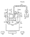
- Fig. 12 shows an alternative arrangement to the gravity feed described above, comprising a pump 400 which draws liquid from a reservoir 410 and supplies it to the feed pipe 210.
- the apparatus forms part of a drinks dispensing unit 300 a high degree of control can be achieved that has not been reliable previously. It has been found in the licenced trade that measures left for some time suffer from evaporation, contraction or even leakage.
- the unit 300 can be made to automatically refill the dispensing chambers 201, 202 on powering up. Also if a particular station has not been used for some time an interim refill routine can be initiated from either the dispense enabling switch 216 or dispense buttons 217, 218 prior to dispense. The same automatic refilling routine would be applied after a tilt condition had been rectified.
- the drinks dispensing unit 300 also affords to the trade an increase in speed and efficiency whereby up to 8 stations may simultaneously dispense single measures with the depression of only one button i.e. button 217.
- the unit 300 may also dispense any combination of singles and doubles, the doubles being dispensed at the stations where the double button 218 has been depressed and the balance in singles upon depression of button 217. Owing to the fact that doubles are dispensed in the same time as it takes to dispense singles and that any combination of singles and/or doubles can be dispensed a considerable saving in time and hence increase in efficiency is realised.
- the unit 300 containing a bi-directional communications port 480 can output diagnostic and stock information direct to an intelligent peripheral 350 such as a point-of-sale terminal or printer, and as such is a self contained system.
- Fig. 13 shows a drinks dispensing unit 300 modified to become a master drinks dispensing unit 340 linked to other drink dispensing units 300 which are "slaves" to it.
- the unit 340 acts as a central data processing station and is linked to an intelligent peripheral 350 such as a point-of-sale terminal or printer.
- the units 300,340, 350 are in communication with each other via the communication ports 480.
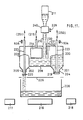
- Fig. 14 shows a drinks dispensing unit 300 housed in a secure cabinet 360. Access to the unit 300 can only be gained via cash acceptor 370 or key operated lock 371 or credit card reader 372. This arrangement is particularly benificial for hotel rooms etc where access to the unit would be by room key into lock 371. In this case any drinks dispensed could be automatically transferred to an intelligent peripheral 350 such as the hotel computer for immediate addition to the bill.
- the cash or credit card operated unit would be particularly useful in very busy establishments where a degree of self service would be helpful, in this case a record of the throughput could be given through port 480 to intelligent peripheral 350 such as a printer.
- Fig. 15 shows a drinks dispensing unit 300 incorporated into an automatic dispensing system.
- a central controller 380 is provided with a screen that has a touch sensitive overlay over the screen.
- the central controller 380 can display various programme menus and messages on the screen.
- One of the menus might be a cocktail dispensing menu. The selection of this menu would result in various cocktails being displayed on the screen.
- a cocktail A was then selected this would then result in the details of the cocktail A being displayed on the screen, these details would include its constituent parts, in what volume the parts are to dispensed and also any special instructions such as garnish, method of mixing and even what glass. Also on this same display screen would be a serve or return to menu instruction. If the serve button was pressed signals would be sent from the controller 380 to the dispensing units 300A, 300B via communication ports 480.
- the units 300A, 300B are shown as having four stations each (but could be eight each station has a dispense enabling switch 216 and a ready indicator 310.
- the cocktail A had a GIN, a double VERMOUTH and a BRANDY and these drinks where situated at stations 300A1, 300A3 and 300B2 respectively.
- the signal from the controller 380 would illuminate the ready indicators 310 at these stations as shown.
- a cocktail shaker for example
- a GIN would be dispensed and the ready indicator 310 turned off at that station
- the operator would then proceed to station 300A3 place the glass on enabling switch 216 and a double VERMOUTH would be dispensed into the shaker and the ready indicator 310 turned off.
- the identical procedure would be carried out at station 300B2 resulting in a BRANDY being dispensed.
- the operator could then look at the screen on 380 for any special instructions such as ice, stir and long glass, it can therefore be seen that anybody whether skilled or not could dispense and mix cocktails correctly.
- controller 380 It is also possible to have other intelligent terminals 385 with screens connected to the central controller 380 thus allowing customers or other operators to look at or feed in their drink requirements into controller 380 for dispensing or not.
- Stock could be outputted from port 480 on controller 380.
- the controller 380 could also be replaced by an intelligent point-of-sale terminal 350 (shown dotted) which would also operate the system.
- units 300A and 300B would still function as independent drinks dispensing units as previously described.
- the drinks dispensing unit 300 has been described as containing eight stations, it is possible to have a higher number of stations if extra micro controllers 234 and power supplies 490 are provided.
Landscapes
- Engineering & Computer Science (AREA)
- Mechanical Engineering (AREA)
- Physics & Mathematics (AREA)
- General Physics & Mathematics (AREA)
- Devices For Dispensing Beverages (AREA)
Applications Claiming Priority (2)
| Application Number | Priority Date | Filing Date | Title |
|---|---|---|---|
| GB898913204A GB8913204D0 (en) | 1989-06-08 | 1989-06-08 | Liquid dispensing apparatus |
| GB8913204 | 1989-06-08 |
Publications (1)
| Publication Number | Publication Date |
|---|---|
| EP0403171A1 true EP0403171A1 (fr) | 1990-12-19 |
Family
ID=10658117
Family Applications (1)
| Application Number | Title | Priority Date | Filing Date |
|---|---|---|---|
| EP90306258A Withdrawn EP0403171A1 (fr) | 1989-06-08 | 1990-06-08 | Dispositif distributeur de liquide |
Country Status (4)
| Country | Link |
|---|---|
| EP (1) | EP0403171A1 (fr) |
| AU (1) | AU4396189A (fr) |
| GB (1) | GB8913204D0 (fr) |
| WO (1) | WO1990015012A1 (fr) |
Cited By (4)
| Publication number | Priority date | Publication date | Assignee | Title |
|---|---|---|---|---|
| WO1995026015A1 (fr) * | 1994-03-23 | 1995-09-28 | Andriussi Francois | Distributeur de doses de produit liquide |
| GB2336153A (en) * | 1998-04-08 | 1999-10-13 | Ecolab Inc | Valved dispensing system |
| WO2000029322A1 (fr) * | 1998-11-19 | 2000-05-25 | Louis George Saunders | Appareil de distribution de liquide |
| FR3044000A1 (fr) * | 2015-11-24 | 2017-05-26 | Gregoire Henry | Dispositif et procede d'echantillonnage d'un liquide |
Families Citing this family (1)
| Publication number | Priority date | Publication date | Assignee | Title |
|---|---|---|---|---|
| US10941978B2 (en) * | 2018-12-10 | 2021-03-09 | Midea Group Co., Ltd. | Refrigerator fluid dispenser with dispensed volume calculation |
Citations (3)
| Publication number | Priority date | Publication date | Assignee | Title |
|---|---|---|---|---|
| GB2144397A (en) * | 1983-08-01 | 1985-03-06 | Garry Ernest Cartwright | Liquid dispensing system and apparatus |
| GB2172577A (en) * | 1985-03-08 | 1986-09-24 | Tecbar Services | Controlling and monitoring liquid dispenser |
| GB2209326A (en) * | 1986-09-12 | 1989-05-10 | Garry Ernest Cartwright | Liquid dispensing apparatus |
-
1989
- 1989-06-08 GB GB898913204A patent/GB8913204D0/en active Pending
- 1989-10-31 AU AU43961/89A patent/AU4396189A/en not_active Abandoned
-
1990
- 1990-06-08 WO PCT/GB1990/000891 patent/WO1990015012A1/fr not_active Ceased
- 1990-06-08 EP EP90306258A patent/EP0403171A1/fr not_active Withdrawn
Patent Citations (3)
| Publication number | Priority date | Publication date | Assignee | Title |
|---|---|---|---|---|
| GB2144397A (en) * | 1983-08-01 | 1985-03-06 | Garry Ernest Cartwright | Liquid dispensing system and apparatus |
| GB2172577A (en) * | 1985-03-08 | 1986-09-24 | Tecbar Services | Controlling and monitoring liquid dispenser |
| GB2209326A (en) * | 1986-09-12 | 1989-05-10 | Garry Ernest Cartwright | Liquid dispensing apparatus |
Cited By (8)
| Publication number | Priority date | Publication date | Assignee | Title |
|---|---|---|---|---|
| WO1995026015A1 (fr) * | 1994-03-23 | 1995-09-28 | Andriussi Francois | Distributeur de doses de produit liquide |
| GB2336153A (en) * | 1998-04-08 | 1999-10-13 | Ecolab Inc | Valved dispensing system |
| US6131774A (en) * | 1998-04-08 | 2000-10-17 | Ecolab Inc. | Flowable material dispenser with automatic shutoff and vessel for receiving flowable material |
| GB2336153B (en) * | 1998-04-08 | 2002-06-26 | Ecolab Inc | Flowable material dispenser with automatic shutoff and vessel for receiving flowable material |
| WO2000029322A1 (fr) * | 1998-11-19 | 2000-05-25 | Louis George Saunders | Appareil de distribution de liquide |
| FR3044000A1 (fr) * | 2015-11-24 | 2017-05-26 | Gregoire Henry | Dispositif et procede d'echantillonnage d'un liquide |
| WO2017089717A1 (fr) * | 2015-11-24 | 2017-06-01 | Henry Grégoire | Dispositif et procédé d'échantillonnage d'un liquide |
| US10759553B2 (en) * | 2015-11-24 | 2020-09-01 | Grégoire HENRY | Device and method for sampling a liquid |
Also Published As
| Publication number | Publication date |
|---|---|
| GB8913204D0 (en) | 1989-07-26 |
| WO1990015012A1 (fr) | 1990-12-13 |
| AU4396189A (en) | 1990-12-13 |
Similar Documents
| Publication | Publication Date | Title |
|---|---|---|
| US4821921A (en) | Liquid dispensing apparatus | |
| US3599833A (en) | Liquid dispenser and recorder means | |
| US4736871A (en) | Liquid measuring dispenser | |
| US6536626B2 (en) | Self-monitoring, intelligent fountain dispenser | |
| US4997012A (en) | Beverage-dispenser control system | |
| CN107212758B (zh) | 一种智能烹饪设备的自动下料系统 | |
| US6427871B1 (en) | Programmable liquid dispensing device with user readable indicators | |
| US20080036615A1 (en) | Automated level indicator for liquids container | |
| US7013932B2 (en) | Automatic portion control system using strain gauge technology | |
| AU2001253902A1 (en) | Self-monitoring, intelligent fountain dispenser | |
| JPH09168486A (ja) | コーヒーひき及び計量制御用電子装置 | |
| CN209090892U (zh) | 一种粉料冲泡现调系统 | |
| EP0403171A1 (fr) | Dispositif distributeur de liquide | |
| GB2173172A (en) | Beverage dispensing system with reserve supply and near-empty signal | |
| EP0032831A2 (fr) | Dispositif pour délivrer une quantité prédéterminée d'une boisson et appareil pour surveiller la délivrance de quantités prédéterminées de boissons | |
| JP2000338115A (ja) | 液体残量検出装置 | |
| JP2003128188A (ja) | 飲料供給装置 | |
| EP0146630A1 (fr) | Procede et dispositif de mesure de la quantite de lait obtenue a l'aide d'une trayeuse automatique | |
| WO2019192483A1 (fr) | Système de bouton-poussoir sélectif, soupape de réduction de pression, dispositif de pesage, récipient appliqué à un système de boisson à la demande multifonctionnel, et système de boisson à la demande multifonctionnel | |
| WO1994003780A1 (fr) | Systeme distributeur pour liqueur en bouteilles | |
| US6332559B1 (en) | Liquor dispensing apparatus | |
| EP0736483A1 (fr) | Dispositif de dosage de concentré pour distributeur de jus de fruit | |
| AU745584B2 (en) | Liquor dispensing apparatus | |
| JPH01100000A (ja) | 灯油の残量警報システム | |
| GB2091215A (en) | Liquid dispensing apparatus |
Legal Events
| Date | Code | Title | Description |
|---|---|---|---|
| PUAI | Public reference made under article 153(3) epc to a published international application that has entered the european phase |
Free format text: ORIGINAL CODE: 0009012 |
|
| AK | Designated contracting states |
Kind code of ref document: A1 Designated state(s): GR |
|
| STAA | Information on the status of an ep patent application or granted ep patent |
Free format text: STATUS: THE APPLICATION IS DEEMED TO BE WITHDRAWN |
|
| 18D | Application deemed to be withdrawn |
Effective date: 19910620 |