EP0403422A2 - Procédé pour la protection d'une installation d'eau chaude contre gel et installation de production d'eau chaude pour sa mise en oeuvre - Google Patents
Procédé pour la protection d'une installation d'eau chaude contre gel et installation de production d'eau chaude pour sa mise en oeuvre Download PDFInfo
- Publication number
- EP0403422A2 EP0403422A2 EP90710014A EP90710014A EP0403422A2 EP 0403422 A2 EP0403422 A2 EP 0403422A2 EP 90710014 A EP90710014 A EP 90710014A EP 90710014 A EP90710014 A EP 90710014A EP 0403422 A2 EP0403422 A2 EP 0403422A2
- Authority
- EP
- European Patent Office
- Prior art keywords
- burner
- water heating
- air
- drive
- heating system
- Prior art date
- Legal status (The legal status is an assumption and is not a legal conclusion. Google has not performed a legal analysis and makes no representation as to the accuracy of the status listed.)
- Granted
Links
Images

Classifications
-
- F—MECHANICAL ENGINEERING; LIGHTING; HEATING; WEAPONS; BLASTING
- F24—HEATING; RANGES; VENTILATING
- F24D—DOMESTIC- OR SPACE-HEATING SYSTEMS, e.g. CENTRAL HEATING SYSTEMS; DOMESTIC HOT-WATER SUPPLY SYSTEMS; ELEMENTS OR COMPONENTS THEREFOR
- F24D19/00—Details
- F24D19/0095—Devices for preventing damage by freezing
Definitions
- the invention initially relates to a method for protecting a water heating system against freezing of the water heater operated with a burner independent of the ambient air.
- the object of the invention is to develop a method which does not require such an outside temperature sensor and which can be carried out using simple technical means.
- the drive of the burner fan is stopped for a predetermined minimum period of time after a predetermined period of time starting with the failure of the air monitor to signal.
- This method therefore makes it unnecessary to record the respective actual outside temperature and moreover ensures that sporadically occurring errors in the air monitor, for example the clamping of a pressure cell, do not lead to a permanent blockage of the burner operation.
- the invention also extends to a method suitable for carrying it out Water heating system, consisting of a water heater with a forced draft burner, preferably a gas burner, which is fed with combustion air via a fan and a heat exchanger, and a preferably pressure-sensitive air monitor, for example a pressure socket, arranged in the combustion air duct, and a general supply of fuel to the burner and control of combustion air, inter alia, control connected to the air monitor and the fan drive via control lines.
- a forced draft burner preferably a gas burner
- a heat exchanger preferably preferably pressure-sensitive air monitor, for example a pressure socket, arranged in the combustion air duct, and a general supply of fuel to the burner and control of combustion air, inter alia, control connected to the air monitor and the fan drive via control lines.
- a circuit with timing elements connected to the general control via a control line and connected to a clock oscillator, is provided in order to maintain the above two time periods.
- a circuit can contain two counters / comparators which are linked to one another via a bistable multivibrator (flip-flop) and AND and OR gates.
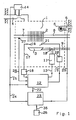
- a water heating system for example a circulation water heating system, comprises a water heater, generally designated 1, with a burner 3, for example a gas burner, which heats a heat exchanger 2 and is supplied with fuel, for example fuel gas, and combustion air.
- a burner for example a gas burner, which heats a heat exchanger 2 and is supplied with fuel, for example fuel gas, and combustion air.
- This burner is independent of the ambient air, i.e. it draws its combustion air from the atmosphere and emits its exhaust gases there.
- the combustion air is supplied from a combustion air duct 4 by means of a fan 5, the exhaust gases of the combustion chamber are discharged by this fan 5 via an exhaust duct 6.
- the flow of the heat exchanger 2 is denoted by 7, the return by 8.
- the fuel supply from a fuel supply line 9 is controlled by a solenoid valve 10, the drive 11 of which is connected via a control line 13 to a general control 12 which also serves to regulate and monitor the operation of the system.
- a general control 12 which also serves to regulate and monitor the operation of the system.
- an air monitor 14 arranged in the combustion air duct 4 for example a pressure can associated with a Venturi tube, connected via a control line 15.
- a burner 3 is assigned a monitoring electrode 16, which is connected to the general control 12 via a control line 17 with a flame measuring amplifier 18 arranged therein.
- a control line 19 extends from the general control 12 to an ignition device 20 and an ignition electrode 21.
- a further control line 22 leads to a circuit 23 according to the invention, into which a control line 24 branches off from the control line 15 and from which a control line 25 for driving the blower 5 extends.
- a clock oscillator 26 is assigned to this circuit 23, which is used for frost protection.
- the system also includes a temperature sensor 27 which is connected to the general control 12 via a control line 28.
- a branch line 30 branches off from the control line 22 at the branching point 29 to the branching point 31, in which a line 32 branches off to the negated input of the OR gate 33.
- the branch Line 30 continues to the input of the AND gate 34, which is fed via an input line 35 from the clock oscillator 26.
- the outputs 36 and 37 of the OR gate 33 and the AND gate 34 are connected to a first counter / comparator 38, specifically the OR gate 33 via a reset input 39.
- the control line 22 branches at the branch point 40 a line 41 to the negated input of a further OR gate 42, which is connected via its other input and via line 43 to a line 44 which leads from the OR gate 33 to a second counter / comparator 45.
- the output of the OR gate 42 is connected to the reset input of a bistable multivibrator (flip-flop) 47, the set input of which is connected via a line 48 to the output of the counter / comparator 38.
- a non-inverted output 49 of this flip-flop 47 connects it to the branch point 51 located on line 50.
- the other inverted output 52 of this flip-flop 47 is connected via a line 53 to the reset input of the second counter / comparator 45.
- a line 55 connects the oscillator 26 to the via a branch point 54 of the line 35 Input of an AND gate 56, which in turn is connected via its output line 57 to the input of the second counter / comparator 45.
- Another AND element 58 arranged in line 22 is connected with its negated input to AND element 56 via line 50 already mentioned above and branch point 51.
- the overflow or underflow of the counters / comparators 38 and 45 is prevented by measures not shown.
- the function of the circuit 23 can also be implemented as a program of a microprocessor and results from its structure in the sense of the invention as follows: If the switch contact of the air monitor 14, for example a pressure socket, remains open as a result of a fault even with sufficient air throughput, the drive of the Blower 5 (and thus burner operation) interrupted for a predetermined period of time, for example for a period of about 15 minutes, but only if the blower 5 was in operation for a predetermined period of time, for example 3 minutes, without feedback from the air watchman 14.
- this shutdown and blocking of the blower and burner operation is ended before the specified minimum duration has expired, if, for example, as a result the completion of a tap, no more heat is requested.
- this prevents excessive cooling of the heat exchanger 2 in the event of a faulty behavior of the air monitor 14, but on the other hand, sporadic errors, for example a mere one-time clamping of a pressure cell, do not permanently block the burner operation.
- the blower 5 is only switched off independently of the level of the outside temperature if this blower has been in operation for a measurable period of time without the air monitor 14 reporting back.
- this switch-off is reversed after a specified period of time or after the heating requirement ceases to exist, for example after a domestic water tap has ended. Then, if there is again a need for heat, another attempt to start the burner operation can take place.
Landscapes
- Engineering & Computer Science (AREA)
- Physics & Mathematics (AREA)
- Thermal Sciences (AREA)
- Chemical & Material Sciences (AREA)
- Combustion & Propulsion (AREA)
- Mechanical Engineering (AREA)
- General Engineering & Computer Science (AREA)
- Regulation And Control Of Combustion (AREA)
- Control Of Combustion (AREA)
- Steam Or Hot-Water Central Heating Systems (AREA)
- Filling Or Discharging Of Gas Storage Vessels (AREA)
- Heat-Pump Type And Storage Water Heaters (AREA)
Applications Claiming Priority (2)
| Application Number | Priority Date | Filing Date | Title |
|---|---|---|---|
| AT1440/89 | 1989-06-13 | ||
| AT0144089A AT397572B (de) | 1989-06-13 | 1989-06-13 | Verfahren zum schutz einer wasserheizanlage gegen ein einfrieren, wasserheizanlage zu dessen durchführung sowie schaltung für eine solche wasserheizanlage |
Publications (3)
| Publication Number | Publication Date |
|---|---|
| EP0403422A2 true EP0403422A2 (fr) | 1990-12-19 |
| EP0403422A3 EP0403422A3 (fr) | 1991-04-17 |
| EP0403422B1 EP0403422B1 (fr) | 1994-03-30 |
Family
ID=3513934
Family Applications (1)
| Application Number | Title | Priority Date | Filing Date |
|---|---|---|---|
| EP90710014A Expired - Lifetime EP0403422B1 (fr) | 1989-06-13 | 1990-06-13 | Procédé pour la protection d'une installation d'eau chaude contre gel et installation de production d'eau chaude pour sa mise en oeuvre |
Country Status (3)
| Country | Link |
|---|---|
| EP (1) | EP0403422B1 (fr) |
| AT (2) | AT397572B (fr) |
| DE (2) | DE59005155D1 (fr) |
Cited By (1)
| Publication number | Priority date | Publication date | Assignee | Title |
|---|---|---|---|---|
| US6368556B1 (en) | 1994-06-28 | 2002-04-09 | Akeda Dental A/S | Apparatus for operational cleaning of dental handpieces |
Family Cites Families (3)
| Publication number | Priority date | Publication date | Assignee | Title |
|---|---|---|---|---|
| SU1038743A2 (ru) * | 1982-03-17 | 1983-08-30 | Предприятие П/Я А-7080 | Устройство автоматической защиты калорифера от замораживани |
| JPS59167646A (ja) * | 1983-03-14 | 1984-09-21 | Sanyo Electric Co Ltd | 温水ボイラの制御装置 |
| SU1180653A1 (ru) * | 1984-04-23 | 1985-09-23 | Предприятие П/Я В-2616 | Система регулировани и защиты от замораживани калорифера приточно-вентил ционной установки |
-
1989
- 1989-06-13 AT AT0144089A patent/AT397572B/de not_active IP Right Cessation
-
1990
- 1990-06-13 DE DE90710014T patent/DE59005155D1/de not_active Expired - Fee Related
- 1990-06-13 AT AT90710014T patent/ATE103698T1/de not_active IP Right Cessation
- 1990-06-13 EP EP90710014A patent/EP0403422B1/fr not_active Expired - Lifetime
- 1990-06-13 DE DE4018985A patent/DE4018985A1/de not_active Withdrawn
Cited By (1)
| Publication number | Priority date | Publication date | Assignee | Title |
|---|---|---|---|---|
| US6368556B1 (en) | 1994-06-28 | 2002-04-09 | Akeda Dental A/S | Apparatus for operational cleaning of dental handpieces |
Also Published As
| Publication number | Publication date |
|---|---|
| EP0403422A3 (fr) | 1991-04-17 |
| DE4018985A1 (de) | 1990-12-20 |
| DE59005155D1 (de) | 1994-05-05 |
| AT397572B (de) | 1994-05-25 |
| ATA144089A (de) | 1993-09-15 |
| ATE103698T1 (de) | 1994-04-15 |
| EP0403422B1 (fr) | 1994-03-30 |
Similar Documents
| Publication | Publication Date | Title |
|---|---|---|
| DE69506475T2 (de) | Steuerungsverfahren für eine Eiserzeugungsmaschine und Gerät dafür | |
| DE69027350T2 (de) | Kontrollverfahren für Kraftstoffbrenner mit heisser Oberflächenzündung | |
| EP4015904A1 (fr) | Procédé et dispositif de protection d'un appareil de chauffage lors de l'allumage d'un mélange d'air et de gaz combustible contenant de l'hydrogène | |
| DE19903305C5 (de) | Verfahren zur Flammüberwachung in einem Fahrzeugheizgerät | |
| DE2700921A1 (de) | Vereisungsdetektor | |
| EP0403422B1 (fr) | Procédé pour la protection d'une installation d'eau chaude contre gel et installation de production d'eau chaude pour sa mise en oeuvre | |
| DE3020228C2 (de) | Sicherheitseinrichtung für brennstoffbeheizte Geräte | |
| DE3339429A1 (de) | Einrichtung zur reduzierung von abgas-schadstoffen | |
| DE1551950B2 (de) | Schaltungsanordnung zur programmsteuerung einer feuerungs anlage | |
| EP0676682B1 (fr) | Capteur solaire avec surveillance de panne | |
| EP0398011B1 (fr) | Système de refroidissement pour dispositif de commande d'un moteur à combustion interne | |
| DE69110214T2 (de) | Steuerungsverfahren für Brenner. | |
| DE4433387A1 (de) | Steuerung | |
| DE2138869A1 (de) | Überwachungseinrichtung für einen Verbrennungsregler | |
| DE4142841C2 (de) | Verfahren zum Starten der Verbrennung eines Brennstoff-Luft-Gemisches in einem Brennraum und Vorrichtung zur Durchführung dieses Verfahrens | |
| EP4089329B1 (fr) | Procédé et dispositif de redémarrage sûr d'un brûleur fonctionnant avec une proportion élevée d'hydrogène | |
| EP1039227B1 (fr) | Procédé de détection et d'evaluation des défaillances d'allumage | |
| EP1039226A2 (fr) | Dispositif d'allumage sans veilleuse | |
| EP0315055B1 (fr) | Méthode pour vérifier une soupape à gaz et dispositif de réalisation de la méthode | |
| DE4038925C2 (fr) | ||
| AT412419B (de) | Verfahren und eine vorrichtung zur überprüfung der zündfunktion einer zündeinrichtung | |
| EP1645803B1 (fr) | Procédé de démarrage d'un appareil de chauffage, en particulier d'un appareil de chauffage pour véhicules | |
| EP0315054B1 (fr) | Procédé de surveillance d'un circuit de surveillance de temps de microprocesseur et dispositif pour la réalisation du procédé | |
| CH658117A5 (en) | Method of testing the monitoring members of a steam boiler and arrangement for implementing the method | |
| CH682011A5 (fr) |
Legal Events
| Date | Code | Title | Description |
|---|---|---|---|
| PUAI | Public reference made under article 153(3) epc to a published international application that has entered the european phase |
Free format text: ORIGINAL CODE: 0009012 |
|
| AK | Designated contracting states |
Kind code of ref document: A2 Designated state(s): AT BE CH DE DK ES FR GB GR IT LI LU NL SE |
|
| PUAL | Search report despatched |
Free format text: ORIGINAL CODE: 0009013 |
|
| AK | Designated contracting states |
Kind code of ref document: A3 Designated state(s): AT BE CH DE DK ES FR GB GR IT LI LU NL SE |
|
| 17P | Request for examination filed |
Effective date: 19910318 |
|
| 17Q | First examination report despatched |
Effective date: 19911118 |
|
| RAP1 | Party data changed (applicant data changed or rights of an application transferred) |
Owner name: N.V. VAILLANT S.A. Owner name: VAILLANT S.A.R.L Owner name: VAILLANT GES.M.B.H Owner name: VAILLANT LTD. Owner name: JOH. VAILLANT GMBH U. CO. Owner name: VAILLANT B.V. Owner name: VAILLANT GMBH |
|
| GRAA | (expected) grant |
Free format text: ORIGINAL CODE: 0009210 |
|
| AK | Designated contracting states |
Kind code of ref document: B1 Designated state(s): AT BE CH DE DK ES FR GB GR IT LI LU NL SE |
|
| PG25 | Lapsed in a contracting state [announced via postgrant information from national office to epo] |
Ref country code: BE Effective date: 19940330 Ref country code: ES Free format text: THE PATENT HAS BEEN ANNULLED BY A DECISION OF A NATIONAL AUTHORITY Effective date: 19940330 Ref country code: NL Effective date: 19940330 Ref country code: DK Effective date: 19940330 Ref country code: GB Effective date: 19940330 Ref country code: FR Effective date: 19940330 Ref country code: SE Free format text: THE PATENT HAS BEEN ANNULLED BY A DECISION OF A NATIONAL AUTHORITY Effective date: 19940330 Ref country code: GR Free format text: LAPSE BECAUSE OF FAILURE TO SUBMIT A TRANSLATION OF THE DESCRIPTION OR TO PAY THE FEE WITHIN THE PRESCRIBED TIME-LIMIT Effective date: 19940330 |
|
| REF | Corresponds to: |
Ref document number: 103698 Country of ref document: AT Date of ref document: 19940415 Kind code of ref document: T |
|
| ITF | It: translation for a ep patent filed | ||
| REF | Corresponds to: |
Ref document number: 59005155 Country of ref document: DE Date of ref document: 19940505 |
|
| PG25 | Lapsed in a contracting state [announced via postgrant information from national office to epo] |
Ref country code: LU Free format text: LAPSE BECAUSE OF NON-PAYMENT OF DUE FEES Effective date: 19940630 |
|
| EN | Fr: translation not filed | ||
| NLV1 | Nl: lapsed or annulled due to failure to fulfill the requirements of art. 29p and 29m of the patents act | ||
| GBV | Gb: ep patent (uk) treated as always having been void in accordance with gb section 77(7)/1977 [no translation filed] |
Effective date: 19940330 |
|
| PLBE | No opposition filed within time limit |
Free format text: ORIGINAL CODE: 0009261 |
|
| STAA | Information on the status of an ep patent application or granted ep patent |
Free format text: STATUS: NO OPPOSITION FILED WITHIN TIME LIMIT |
|
| 26N | No opposition filed | ||
| PG25 | Lapsed in a contracting state [announced via postgrant information from national office to epo] |
Ref country code: IT Free format text: LAPSE BECAUSE OF NON-PAYMENT OF DUE FEES;WARNING: LAPSES OF ITALIAN PATENTS WITH EFFECTIVE DATE BEFORE 2007 MAY HAVE OCCURRED AT ANY TIME BEFORE 2007. THE CORRECT EFFECTIVE DATE MAY BE DIFFERENT FROM THE ONE RECORDED. Effective date: 20050613 |
|
| PGFP | Annual fee paid to national office [announced via postgrant information from national office to epo] |
Ref country code: CH Payment date: 20080606 Year of fee payment: 19 |
|
| PGFP | Annual fee paid to national office [announced via postgrant information from national office to epo] |
Ref country code: AT Payment date: 20080520 Year of fee payment: 19 |
|
| PGFP | Annual fee paid to national office [announced via postgrant information from national office to epo] |
Ref country code: DE Payment date: 20080515 Year of fee payment: 19 |
|
| REG | Reference to a national code |
Ref country code: CH Ref legal event code: PL |
|
| PG25 | Lapsed in a contracting state [announced via postgrant information from national office to epo] |
Ref country code: CH Free format text: LAPSE BECAUSE OF NON-PAYMENT OF DUE FEES Effective date: 20090630 Ref country code: LI Free format text: LAPSE BECAUSE OF NON-PAYMENT OF DUE FEES Effective date: 20090630 |
|
| PG25 | Lapsed in a contracting state [announced via postgrant information from national office to epo] |
Ref country code: DE Free format text: LAPSE BECAUSE OF NON-PAYMENT OF DUE FEES Effective date: 20100101 Ref country code: AT Free format text: LAPSE BECAUSE OF NON-PAYMENT OF DUE FEES Effective date: 20090613 |