EP0403973B1 - Dispositif de commande de commutation d'un réseau en anneau - Google Patents
Dispositif de commande de commutation d'un réseau en anneau Download PDFInfo
- Publication number
- EP0403973B1 EP0403973B1 EP90111330A EP90111330A EP0403973B1 EP 0403973 B1 EP0403973 B1 EP 0403973B1 EP 90111330 A EP90111330 A EP 90111330A EP 90111330 A EP90111330 A EP 90111330A EP 0403973 B1 EP0403973 B1 EP 0403973B1
- Authority
- EP
- European Patent Office
- Prior art keywords
- transmission line
- switching
- transmission
- ring network
- control
- Prior art date
- Legal status (The legal status is an assumption and is not a legal conclusion. Google has not performed a legal analysis and makes no representation as to the accuracy of the status listed.)
- Expired - Lifetime
Links
Images


Classifications
-
- H—ELECTRICITY
- H04—ELECTRIC COMMUNICATION TECHNIQUE
- H04J—MULTIPLEX COMMUNICATION
- H04J14/00—Optical multiplex systems
- H04J14/02—Wavelength-division multiplex systems
- H04J14/0287—Protection in WDM systems
- H04J14/0293—Optical channel protection
- H04J14/0295—Shared protection at the optical channel (1:1, n:m)
-
- H—ELECTRICITY
- H04—ELECTRIC COMMUNICATION TECHNIQUE
- H04J—MULTIPLEX COMMUNICATION
- H04J14/00—Optical multiplex systems
- H04J14/02—Wavelength-division multiplex systems
- H04J14/0278—WDM optical network architectures
- H04J14/0283—WDM ring architectures
-
- H—ELECTRICITY
- H04—ELECTRIC COMMUNICATION TECHNIQUE
- H04L—TRANSMISSION OF DIGITAL INFORMATION, e.g. TELEGRAPHIC COMMUNICATION
- H04L12/00—Data switching networks
- H04L12/28—Data switching networks characterised by path configuration, e.g. LAN [Local Area Networks] or WAN [Wide Area Networks]
- H04L12/42—Loop networks
- H04L12/437—Ring fault isolation or reconfiguration
Definitions
- the present invention relates to a ring network which is applied to a local area network (LAN) and, more particularly, to a ring network switching control device for automatically reconfiguring a network in the event of a transmission-line failure by use of a duplex transmission line.
- LAN local area network
- LANs Local area networks
- communication nodes communication control devices which accommodate terminals and the like
- a transmission line in the form of a ring thus allowing data interchange among distributed terminals and computers have been used widely.
- duplex transmission lines In general, an advantage of duplex transmission lines is that, even when a fault occurs in one of the transmission lines, another transmission line can be used to continue the data communication and thus a reliable system is obtained.
- the duplex transmission lines as two loops for transmitting data in reverse directions, even when both of the two lines are cut, or when a fault occurs in a node, the data communication can be maintained at a minimum scale of the system through a loop back.
- the transmission line is reconfigured.
- the present invention provides a system which enables the formation of a loop back and the resetting of each node (including a supervisory node), to obtain a flexible system operation.
- the parent station receives control information representing the state of transmission line 3 from respective communication nodes at regular intervals for centralized control of the entire state of the network.
- the parent station decides its state and transmits control information to each of communication nodes to control its switches (not shown), thereby switching between the #1 and #2 systems of transmission line 3 or performing a loopback of transmission line 3 for reconfiguration of the network. That is, the child stations, operate subordinately as prompted by the parent station.
- USP4930199 (which corresponds to Japanese unexamined Kokai Publication 1-164,141) disclosed a prior art for performing a communication control autonomously by enabling respective communication node to use the control data.
- the present invention is directed to a further specific and concrete technology for performing an autonomous control.
- US-A-4 648 088 discloses a distributed control time division multiplex ring communication apparatus comprising a plurality of nodes connected together by interchanged trunks, main and standby paths, in a ring type of closed loop configuration.
- Each node in the system includes transmitters and receivers on the main and standby paths along with bridging and switching circuits connected to data failure and other failure detection circuits for operating same arranged such that data and alarm signals are transmitted in the first direction on the main path around the closed loop and in an opposite direction on the standby path.
- the system is arranged such that if a failure occurs only on the main path and the standby path is unaffected, all communications are switched to the standby path.
- the circuitry is switched to a configuration where the closed loop comprises portions of the standby and main path and the nodes that are adjacent the failure are connected such that the standby path bypasses those nodes whereby there is direct communication between the two nodes adjacent the failure.
- each node has only one bypass, and therefore there are situations where certain stations cannot be reconfigured.
- GB-A-2 194 713 discloses a method of restoring a dual transmission line which connects respective stations to make a local area network.
- JP-A-59 215152 discloses a loop transmission system wherein to attain normal communication at the generation of a failure, an auxiliary transmission line possible for two-way transfer between a loop control station and a node station to change a part of the transmission line to the auxiliary transfer line by means of a modification command is provided.
- Figure 1A illustrates a general configuration of a ring network.
- a supervisory node hereinafter abbreviated to SN
- SN supervisory node
- INs communication nodes
- 2-1 to 2-5 child stations
- SN supervisory node
- INs communication nodes
- transmission line 3 is switched to the standby #2-system transmission line for subsequent operation.
- transmission line 3 is looped back from the #1 system to the #2 system at IN 2-1, and likewise transmission line 3 is looped back from the #2 system to the #1 system so that the network is reconfigured for subsequent operation.
- FIG. 2A is a block diagram illustrating a first principle of the present invention
- These transmission lines are implemented as a LAN (local area network) formed of, for example, optical fiber cables.
- Communication node 6a comprises various sections which will be described below. Note that the other communication nodes 6b, 6c and so on have the same configuration.
- control information transmitting sections 9a-1 and 9a-2 are provided. These sections transmit control information 8j-1 and 8j-2 representing the states of transmission lines 7-1 and 7-2 to communication nodes 6b and 6c via transmission lines 7-1 and 7-2, respectively.
- control information receiving sections 10a-1 and 10a-2 are provided. These sections supervise the states of transmission lines 7-1 and 7-2, for example, receive levels, and receive control information 8i-1 and 8i-2 from communication nodes 6b and 6c, respectively.
- a transmission line switching section 11a is provided. This section switches the connecting state of each of transmission lines 7-1 and 7-2. It switches between transmission lines 7-1 and 7-2 to determine which of them is to be supplied with transmit or receive data within communication node 6a. It also performs such connection switching operations as short-circuiting the input side and output side of each of transmission lines 7-1 and 7-2 so as to allow communication data on the transmission lines to merely pass, or loops the transmission line from 7-1 back to 7-2 or from 7-2 back to 7-1.
- control section 12a This section prompts transmission line switching section 11a to perform a switching operation and control information transmitting section 9a-1 and 9a-2 to transmit new control information 8j-1 and 8j-2 on the basis of results of the supervision of each of the transmission lines and the reception of control information 8i-1 and 8i-2 by control information receiving sections 10a-1 and 10a-2.
- Control information 8k-1 and 8k-2 is transmitted between communication nodes 6b and 6c.
- control section 12a thereby controls the connecting state of the transmission lines in transmission line switching section 11a in accordance with predetermined rules. Also, control section 12a prompts control information transmitting sections 9a-1 and 9a-2 to transmit new control information corresponding to the state in accordance with predetermined rules. The above operation also applies to the other communication nodes 6b and 6c.
- control section 12a may store these rules in the form of a table. If it does, when a change of state occurs, control section 12a has only to refer to the table for the transition to a new state. This simple control will permit the above operation to be achieved and the network to be reconfigured quickly.
- the above rules may be implemented by hard-wired logic, such as sequential circuits, for faster control.
- Figure 2B is a second block diagram of the present invention. As in Figure 2A, a plurality of communication nodes 14a, 14b, 14c and so on are sequentially connected in a ring by duplexed transmission lines 15-1 and 15-2, thereby forming a ring network.
- Communication node 14a comprises various sections which will be described below.
- the other communication nodes have the same configuration as communication node 14a, as shown.
- a hybrid outputting section 16a is provided.
- This section outputs transmission data 20a to be communicated to other communication nodes 14b and 14c, to two transmission lines 15-1 and 15-2 in a hybrid manner (simultaneously). That is, in the second principle, transmission data 20a is outputted to both transmission lines 15-1 and 15-2 unconditionally.
- supervisory sections 17a-1 and 17a-2 are provided. These sections supervise an alarm on the receiving sides of transmission lines 15-1 and 15-2. They perform a supervision to determine whether or not data can be received from their corresponding respective transmission line 15-1 or 15-2 within a specified period. If data cannot be received, the section gives an alarm indicating a failure in the transmission line.
- a reception switching section 18a is provided. This section switches between the transmission lines to receive data 21a.
- control section 19a This section performs switching control on reception switching section 18a on the basis of the supervised states by supervisory sections 17a-1 and 17a-2.
- a switching control section may be provided for performing a connection switching operation such as short-circuiting the input and output sides of transmission lines 15-1 and 15-2 to simply allow communication data on the transmission lines to pass, or loops the transmission line from 15-1 back to 15-2 or from 15-2 block to 15-1. If it does, communication node 14a will be allowed to have the function of a transit node as well as the function of a communication node adapted to transmit data 20a and receive data 21a.
- control section 19a controls reception switching section 18a. That is, with data 21a received from transmission line 15-1 through supervisory section 17a-1 and reception switching section 18a, if supervisory section 17a-1 gives an alarm indicating that data cannot be normally received, control section 19a switches reception switching section 18a. Thereafter, data 21a is received from transmission line 15-2 through supervisory section 17a-2 and reception switching section 18a.
- the above operation also applies to other communication nodes 6b and 6c.
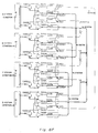
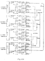
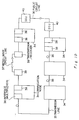
- Figure 3 illustrates a configuration of a first preferred embodiment of the present invention. It illustrates the configuration of each of the communication nodes IN 2-1 to IN 2-5 in a general ring type of LAN as shown in Figures 1A to 1C. Since the present embodiment is not directed to a system in which the network is reconfigured under centralized control of supervisory node SN 1, the configuration of SN 1 will not be referred to in particular.
- transmission line 3 (refer to Figures 1A to 1C) has a #1-system transmission line for transmission, a #2-system transmission line for reception, a #1-system transmission line for reception and a #2-system transmission line for light-wavelength division multiplexed in one optical fiber cable, the #1 system being multiplexed using a wavelength of ⁇ 2.
- the #1 and #2 systems may be formed of separate optical fiber cables.
- WDM 27-1 Multiplexing section (hereinafter referred to as WDM) 27-1 multiplexes a #1-system transmission output from #1-system electricity-to-light conversion section ⁇ 1OS of optical conversion section (hereinafter referred to as OPT) 26-1 on transmission line 3 and demultiplexes a #2-system receive input form transmission line 3 for application to #2-system light-to-electricity conversion section ⁇ 2OR of OPT 26-1.
- WDM 27-2 also performs this operation on a #1-system receive input and a #2-system transmit output among #1-system light-to-electricity conversion circuit ⁇ 1OR, #2-system electricity-to-light conversion circuit ⁇ 2OS and transmission line 3.
- ⁇ 1OS or ⁇ 2OS in OPT 26-1 or 26-2 converts an electric output signal from a ring switch (hereinafter referred to as RSW) 25 to a light signal having a wavelength of ⁇ 1 or ⁇ 2 for application to WDM 27-1 or 27-2.
- RSW ring switch
- ⁇ 1OR or ⁇ 2OR in OPT 26-1 or 26-2 converts a light input signal having a wavelength of ⁇ 1 or ⁇ 2 from WDM 27-1 or 27-2 to an electric signal for application to RSW 25.
- RSW 25 selectively connects the input and output of multiplexing/demultiplexing section (hereinafter referred to as MUX/DMUX) 24 to either OPT 26-1 or OPT 26-2.
- MUX/DMUX multiplexing/demultiplexing section
- RSW 25 determines which of the #1 system or #2 system transmission lines is to be connected to MUX/DMUX 24.
- RSW 25 may connect ⁇ 1OR and ⁇ 1OS or ⁇ 2OR and ⁇ 2OS directly.
- MUX/DMUX 24 multiplexes or demultiplexes a time-division multiplexed signal having a transmission rate of 32 Mbps which is transmitted between time switch (hereinafter referred to as TSW) 23 and RSW 25.
- TSW 23 determines which of 480 channels of the time-division multiplexed signal of 32 Mbps in transmission rate is to be allotted to an input/output signal having a transmission rate of 64 kbps in interface (hereinafter referred to as IF) 22. For other channels which are not allotted to the signal, TSW 23 directly connects its receive input from MUX/DMUX 24 to its transmit output to MUX/DMUX 24.
- IF interface
- IF 22 is an interface circuit adapted to make a a connection between a transmission signal S from or a receive signal R to a terminal not shown and TSW 23.
- Control section 28 performs the entire control of IF 22, TSW 23, MUX/DMUX 24, RSW 25 and OPTs 26-1 and 26-2.
- Control section 28 supervises whether or not receive signals, which are light signals, are normally received by ⁇ 1OR and ⁇ 2OR in OPT 26-1. Suppose the state in which a reduction in the receive level of the light signal is detected in ⁇ 1OR to be RX1 and the state in which a reduction in the receive level of the light signal is detected in ⁇ 2OR to RX2.
- control section 28 On detection of RX1, namely, a reduction in the receive level of the #1 system receiving side, control section 28 first outputs via ⁇ 2OS return information SEND2 of RX1 to the #2 system transmission side. This output is in the direction of the input signal whose receive level is detected. At the same time, control section 28 outputs failure information NG1 of the #1 system transmission line ( ⁇ 1 loop) to the #1 system transmission side corresponding to RX1.
- control section 28 On detection of RX2, namely, a reduction in the receive level of the #2 system receiving side, control section 28 first outputs via ⁇ 1OS return information SEND1 of RX2 to the #1 system transmission side. This output is in the direction of the input signal whose receive level is detected. At the same time, control section 28 outputs failure information NG2 of the #2 system transmission line ( ⁇ 2 loop) to the #2 system transmission side corresponding to RX2.
- control section 28 In a communication node which has not yet detected RX1 or RX2, when control section 28 receives failure information NG1 from the next node via ⁇ 1OR on the #1 system receiving side, it outputs via ⁇ 1OS the failure information NG1 as it is to the #2 system transmitting side. This output is in the direction of the input signal.
- the six types of failure information of Figure 4 will have a fixed pattern depending on the failure conditions in transmission line 3. How to set the connection state of RSW of Figure 3 for each of the failure conditions may be determined in advance. In the present embodiment, this property is used by control section 28 in each communication node to control the connecting state of RSW 25 on the basis of six types of failure information of Figure 4 and in accordance with the following conditions.
- the connecting state of each communication node is shown at the top of Figure 5A.
- the circuit designated by MUX corresponds to MUX/DMUX 24 of Figure 3.
- SW0S, SW2S, SW0R, SW1R and SW2R conceptually represent the connecting states of transmission and receive signals in RSW 25.
- an input received from the #1 system transmission line is entered into MUX/DMUX24 via ⁇ 1OR, SW1R and SW0R, while a transmission output of MUX/DMUX 24 is output to the #1 system transmission line via SW0S, SW1S and ⁇ 1OS. That is, the #1 system is employed.
- ⁇ 2OR and ⁇ 2OS are short-circuited by SW2R and SW2S.
- the connecting patterns in RSW 25 and the output patterns of failure information from ⁇ 1OS or ⁇ 2OS will have 17 types of patterns represented by condition 1 through condition 17, as illustrated in Figures 5A through 5E.
- condition 1 through condition 17 as illustrated in Figures 5A through 5E.
- 26 conditions can occur as a result of combinations of six types of failure information, as shown in Figure 4. However, seventeen following conditions actually occur.
- condition 1 of Figure 5A corresponds to the case where the state RX1, which represents a reduction in the receive level of the #1 system receiving side, is detected.
- the connecting states are changed as shown and, at the same time, failure information NG1 is output from ⁇ 1OS to the #1 system transmitting side and return information SEND2 is output from ⁇ 2OS to the #s system transmission side. This also applies to conditions 2 through 17.
- case 1 of Figures 6A and 7A represents a case where, when the #1 system transmission line is employed, a failure occurs in #1 system between B station and C station.
- the receive level reduced state RX1 at ⁇ 1OR is detected in B station as shown in Figure 6A so that it enters the connecting state in condition 1 of Figure 5A.
- failure information NG1 is sent from B station to A station over the #1 system transmission line and return information SEND2 is returned from B station to C station over the #2 system transmission line.
- failure information NG1 is transferred from station to station, i.e., from A station to D station and from D station to C station.
- a station placed in the connecting state of condition 13 of Figure 5D and station C is placed in the connecting state of condition 14 of Figure 5D.
- the transmission line is switched from #1 system to #2 system for employment of the network, as indicated by the bold lines in Figure 6A or Figure 7A.
- Case 2 of Figures 6B and 7B corresponds to a case where failures occur in both the #1 and #2 systems between B station and C station at the time of network employment by use of the #1 system transmission line.
- the receive level reduced state RX1 at ⁇ 1OR is detected in B station and the receive level reduced state RX2 at ⁇ 2OR is detected in C station.
- a station and D station operate in an interlocking manner so that they enter the connecting state of condition 15 of Figure 5D.
- B station enters the connecting state of condition 2 of Figure 5A and C station enters the connecting state of condition 7 of Figure 5B.
- the transmission line is looped from the #1 system back to the #2 system in C station and from the #2 system back to the #1 system in B station as indicated by the bold lines in Figure 6B or Figure 7B.
- an alternative route is established as shown in Figure 7B to circumvent the failed portions.
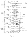
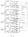
- Figure 8 shows a configuration of the second preferred embodiment of the present invention.
- This embodiment which is similar to the first preferred embodiment, shows the configuration of one of the communication nodes IN2-1 to IN2-5 in a general ring type LAN shown in Figures 1A to 1C.
- transmission line 3 (which should be referred to in Figures 1A to 1C) comprises an optical fiber cable in which the transmission side of the #1 system and the receiving side of the #2 system, the receiving side of the #1 system and the transmission side of the #2 system are optical-wavelength multiplexed.
- the #1 and #2 systems may be formed of separate optical fiber cables.
- the circuit corresponding to WDM 27-1 and 27-2 of the first preferred embodiment may be omitted.
- the second preferred embodiment does not have a circuit corresponding to RSW 25 of the first preferred embodiment shown in Figure 3 and the input side of OS#1 and OS#2 and the output side of OR#1 and OR#2 are connected to MUX-DMUX 32-1 and 32-2.
- MUX/DMUX 32-1 and 32-2 perform multiplexes or demultiplexes by using time divisional multiplexed signals having transmission speeds of 32 Mbps, forming an input and output at passing portion 31 and an input and output at OS#1, OS#2, OR#1 and OR#2 in the same manner as MUX/DMUX 24 in the first preferred embodiment shown in Figure 3.
- Passing portion 31 determines to which of 480 channels of a time divisional multiplexing signal having a transmission speed of 32 Mbps in MUX/DMUX 32-1 or 32-2 the input and output signal at branch switching portion 30 is assigned. In the unassigned channels, the receiving side input from MUX/DMUX 32-1 is relayed to the output of the transmission side to MUX/DMUX 32-2. Conversely, the input of the receiving side from MUX/DMUX 32-2 is relayed to the output of the transmission side to MUX/DMUX 32-1.
- the unit in which the above assignment is performed is not limited to a single channel unit but comprises an HG unit, as described later.
- Branch switching unit 30 is the most characteristic portion of the present embodiment and comprises a hybrid output portion H and a receive switching portion SW.
- Hybrid output portion H comprises a circuit for outputting the transmission output from IF 29 to two systems.
- the transmission output is transmitted to MUX/DMUX 32-1 and the transmission line of the #1 system through OS#1.
- the transmission output is also transmitted from a passing portion 31 to MUX/DMUX 32-2 and the transmission line of #2 system through OS#2.
- Receive switching portion SW selects one of the receiving input from the #1 system receiving side through MUX/DMUX 32-2 and passing portion 31 and the receiving input from the #2 system receiving side through MUX/DMUX 32-1 and passing portion 31 and outputs the selected input to IF 29.
- IF 29 is an interface circuit for performing a connection between a transmission signal S or a receive signal R for a terminal not shown and branch switching portion 30 in the same manner as IF in the first preferred embodiment shown in Figure 3.
- Control unit 33 performs a whole control of IF 29, branch switching portion 30, passing portion 31, MUX/DMUX 32-1, 32-2, OS#1, OS#2, OR#1 and OR#2 of the above structure.
- the respective communication shown in Figure 8 in the present embodiment autonomously performs a switching of a transmission line 3 between #1 system and #2 system, thereby reconstructing the network.
- the connection logic is simple.
- Control unit 33 performs a supervision to determine whether or not the receiving signal of an optical signal is normally received. Where an alarm of a receive input is detected in OR#1, control unit 33 enables a switching of receive switching unit SW in branch switching unit 30 to select a receive input from MNUX/DMUX 32-1. Conversely, where a receive input alarm is detected at OR#2, receive switching portion SW in branch switching unit 30 is switched to select a receive input from MUX/DMUX 32-2.
- the signal transmitted on transmission line 3 is a time divisional multiplexing signal of 480 channels having a transmission speed of 32Mbps.
- the embodiment has a receiving alarm in an HG unit and performs a switching in an HG unit.
- Connection of passing portion 31 with IF 29 side is also performed in an HG unit and, for example, HG1 may be connected to IF 29 and HG2-HG80 merely relay by MUX/DMUX 32-1 and 32-2.
- the first preferred embodiment controls a switching of both transmission and receive sides in RSW 25 in accordance with failure information.
- the second preferred embodiment uses only an alarm on the receiving side for failure information and thus switches the receiving side to either #1 system or #2 system.
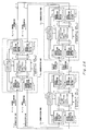
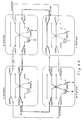
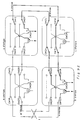
- Figures 9A to 9F show cases of four communication nodes comprising A station to D station.
- the number of communication nodes is not limited to four and may be discretional.
- Figure 9A designates a case 1 in which a normal operation is performed and in which a data communication is mutually performed between B station and D station.
- the present embodiment performs a communication using both transmission lines where #1 system and #2 system are in a normal state.
- a portion designated by "H" corresponds to a hybrid outputting section H in Figure 8 and SW
- OR correspond to a receiving switching unit SW.
- SW1S, SW2S, SW1R and SW2R respectively, conceptionally show a state of connection of a transmit and receive signal in passing portion 31.
- the communication data from B station is output from hybrid outputting portion H to a transmission line of #1 system through SW1S and is input to A station.
- a station relays the communication data through SW1R and SW1S to D station.
- D station receives the communication data input through a transmission line of #1 system from A station via SW1R to SW0R.
- the communication data from D station is output from hybrid output portion H to a transmission line of #2 system through SW2S and input to A station.
- a station merely relays the communication data through SW2R and SW2S and inputs the communication data into B station.
- B station receives the communication data input through a transmission line of #2 system from D station via SW2R to SW0R.
- Case 2 shown in Figure 9B shows a case in which a failure occurs between A station and D station of #1 system in the normal state of the case 1.
- an alarm received at OR#1 Figure 8
- SW0R receiving switching SW in Figure 8
- the communication data from D station to B station is transmitted as shown by the bold line in Figure 9B, using the transmission line of #2 system in the same manner as in Figure 9A.
- the communication data from B station to D station is output from hybrid output portion H of B station to the transmission line of #2 system through SW2S as shown by the bold line and is input to C station.
- the communication data is relayed through SW2R and SWSR of C station and input to D station. Therefore, the communication data from B station is received by D station through the transmission line of #2 system and through SW2R and SW0R and is received by D station. In this case, D station automatically outputs the communication data from hybrid outputting portion H to the transmission lines comprising #1 system and #2 system and it is not necessary to switch from #1 system to #2 system on the transmission side. Therefore, a failure on the transmission line in #1 system between A station and D station is avoided.
- the case 3 shown in Figure 9C designates the case where a failure occurs between A station and D station in #2 system in the case 1 designating the normal state.
- the receive alarm is detected in B station and SW0R is switched from #2 system to #1 system, thereby enabling the communication data from D station to B station to be transmitted along the transmission line designated by a bold line in Figure 9C.
- case 4 shown in Figure 9D
- a failure occurs on a transmission line of both #1 system and #2 system between A station and D station in the normal state of case 1.
- a receive alarm is detected at OR#1 ( Figure 8) in both B and D stations.
- SW0R of both stations is switched from #1 system to #2 system. Therefore, both the communication data from B station to D station and the communication data from D station to B station are both switched from #1 system to #2 system as shown by the bold line in Figure 9D. Therefore, the transmission line failure in both #1 system and #2 system between A station and D station is avoided.
- Case 5 shown in Figure 9E designates the case where a failure occurs on both transmission lines for #1 system and #2 system between A station and B station in the case 1 designating the normal state.
- the receive alarm is detected in B station and D station and thus both SWORs are switched from #1 system to #2 system. Accordingly, both communication data from B station to D station and communication data from D to station to B station are switched to a path designated by a bold line shown in Figure 9E.
- case 5 shown in Figure 9F designates the case where a failure occurs in both #1 system and #2 system between B station and C station in the case 1 designating the normal state.
- both communication data from B station to D station and communication data from D station to B station need not switch the data communication lines.
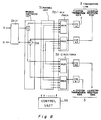
- FIG 10 shows a view of the whole structure of the third preferred embodiment formed as an application of the first and second preferred embodiments.
- a microwave circuit line 33 through transmitter and receiver 39 and a public circuit line 36 through DSU 40 may be provided in a network within communication node 34 in addition to a normal transmission line 35.
- an interface operation with an external apparatus is performed by an interface apparatus (multiplying apparatus) 38.
- FIG 11 shows a view of the whole structure of the fourth embodiment formed as an application of the second preferred embodiment.
- a detour transmission line 41 is provided between predetermined stations, for example, between A station and C station, in addition to a normal ring-type transmission line of #1 system and #2 system.
- Branch switching portion 42-1 is provided at A station and branch switching portion 42-2 is similarly provided at C station and there connected by multiplexing portions 43-1 and 43-2.
- the transmission data on the transmission side are output to detour transmission line 41 through hybrid outputting portion H in branch switching portion 42-1 and are transmitted to both the normal transmission lines of #1 system and #2 system through hybrid outputting portion H in A station. The same applies to C station side.
Landscapes
- Engineering & Computer Science (AREA)
- Computer Networks & Wireless Communication (AREA)
- Signal Processing (AREA)
- Small-Scale Networks (AREA)
Claims (14)
- Dispositif de commande de commutation de réseau en anneau destiné à être utilisé avec un réseau en anneau dans lequel chacun d'une pluralité de noeuds de communication (6a ; 6b ; 6c) est connecté dans un anneau via une ligne de transmission duplexée (7-1 ; 7-2), chaque noeud de communication comprenant :
un moyen d'émission d'information de commande (9a-1, 9a-2 ; 9b-1, 9b-2 ; 9c-1, 9c-2) pour émettre une information de commande représentant l'état de sa ligne de transmission associée pour un autre noeud de communication via sa ligne de transmission associée ;
un moyen de réception d'information de commande (10a-1, 10a-2 ; 10b-1, 10b-2 ; 10c-1, 10c-2) pour surveiller l'état de sa ligne de transmission associée et pour recevoir une information de commande depuis un autre noeud de communication via sa ligne de transmission associée ;
un moyen de commutation de ligne de transmission (11a ; 11b ; 11c) pour commuter l'état de connexion de sa ligne de transmission associée ; et
un moyen de commande (12a ; 12b ; 12c) pour demander au moyen de commutation de ligne de transmission (11a ; 11b ; 11c) de réaliser une commande de commutation et au moyen d'émission d'information de commande d'émettre une nouvelle information de commande conformément aux résultats de la surveillance de l'état de la ligne de transmission et de la réception de l'information de commande par le moyen de réception d'information de commande de manière à ce que chacun desdits noeuds de communication (6a ; 6b ; 6c) réalise une commande distribuée conformément à une variation d'état du réseau,
dans lequel :
ledit moyen de commutation de ligne de transmission (11a ; 11b ; 11c) est conçu pour réaliser une commutation pour déterminer la ligne de transmission pour laquelle une opération d'entrée d'une donnée de réception est réalisée ou pour laquelle une opération de sortie d'une donnée d'émission est réalisée, une commutation pour tout simplement faire passer des données de communication le long d'une ligne de transmission en mettant en court-circuit un côté d'entrée et un côté de sortie pour les deux lignes de transmission ou pour l'une ou l'autre des lignes de transmission, ou une commutation pour faire boucler en retour une ligne de transmission sur l'autre ligne de transmission. - Appareil de commande de commutation de réseau en anneau selon la revendication 1, dans lequel :
ledit moyen de commande (12a ; 12b ; 12c) comporte une table pour déterminer une règle de commutation pour ledit moyen de commutation de ligne de transmission (11a ; 11b ; 11c) et une règle d'instruction d'émission pour une nouvelle information de commande pour ledit moyen d'émission d'information de commande (9a-1, 9a-2 ; 9b-1, 9b-2 ; 9c-1, 9c-2) et réalise ladite commande de commutation et ladite commande d'instruction d'émission de ladite nouvelle information de commande par report à la table sur la base de l'état de lignes de transmission respectives de surveillance et du résultat reçu de ladite information de commande conformément audit moyen de réception d'information de commande (10a-1, 10a-2 ; 10b-1, 10b-2 ; 10c-1, 10c-2). - Appareil de commande de commutation de réseau en anneau selon la revendication 1, dans lequel :
ledit moyen de commande (12a ; 12b ; 12c) comprend un circuit séquentiel pour réaliser une commande de commutation pour ledit moyen de commutation de ligne de transmission et pour réaliser une commande d'instruction d'émission d'une nouvelle information de commande dudit moyen d'émission d'information de commande (9a-1, 9a-2 ; 9b-1, 9b-2 ; 9c-1, 9c-2) sur la base d'un état de surveillance desdites lignes de transmission respectives par ledit moyen de réception d'information de commande (10a-1, 10a-2 ; 10b-1, 10b-2 ; 10c-1, 10c-2) et du résultat reçu de ladite information de commande. - Appareil de commande de commutation de réseau en anneau selon la revendication 1, dans lequel :
lesdites lignes de transmission respectives (7-1 ; 7-2) sont formées par un câble à fibre optique. - Appareil de commande de commutation de réseau en anneau selon la revendication 4, dans lequel :
l'information transmise sur des lignes de transmission respectives (7-1 ; 7-2) est multiplexée optiquement. - Appareil de commande de commutation de réseau en anneau selon la revendication 1, dans lequel :
le réseau en anneau comprend un réseau local. - Appareil de commande de commutation de réseau en anneau selon la revendication 1, dans lequel :
lesdites lignes de transmission respectives (7-1 ; 7-2) incluent soit une ligne de circuit micro-ondes (37) soit une ligne de circuit publique (36) soit les deux. - Dispositif de commande commutation de réseau en anneau destiné à être utilisé avec un réseau en anneau dans lequel chacun d'une pluralité de noeuds de communication (14a ; 14b ; 14c) est connecté dans un anneau via une ligne de transmission duplexée (15-1 ; 15-2), chaque noeud de communication comprenant:
un moyen de sortie hybride (16a ; 16b ; 16c) pour émettre en sortie des données d'émission sur deux lignes de transmission de façon hybride ;
un moyen de surveillance (17a-1, 17a-2 ; 17b-1, 17b-2 ; 17c-1, 17c-2) pour surveiller une alarme sur un côté de réception de chaque ligne de transmission ;
un moyen de commutation de réception (18a ; 18b ; 18c) pour commuter une ligne de transmission pour lui permettre de recevoir des données;
un moyen de commande (19a ; 19b ; 19c) pour réaliser une commande de commutation sur le moyen de commutation de réception (18a ; 18b ; 18c) sur la base de l'état surveillé par le moyen de surveillance (17a-1, 17a-2 ; 17b-1, 17b-2 ; 17c-1, 17c-2) ; et
un moyen de commande de commutation pour sélectionner un mode de commutation dans lequel un côté d'entrée et un côté de sortie sont mis en court-circuit pour les deux lignes de transmission ou pour l'une ou l'autre des lignes de transmission respectives pour simplement laisser passer les données d'émission sur la ligne de transmission ou un mode de commutation pour un bouclage en retour de l'une des lignes de transmission sur l'autre ligne de transmission. - Appareil de commande de commutation de réseau en anneau selon la revendication 8, dans lequel :
ledit moyen de surveillance (17a-1, 17a-2 ; 17b-1, 17b-2 ; 17c-1, 17c-2) détermine si oui ou non le noeud peut recevoir les données provenant de la ligne de transmission du type anneau duplex pendant la période temporelle prédéterminée et produit une alarme pour notifier une défaillance d'une ligne de transmission lorsqu'il ne reçoit pas les données pendant la durée prédéterminée. - Appareil de commande de commutation de réseau en anneau selon la revendication 8, dans lequel :
lesdites lignes de transmission respectives (15-1 ; 15-2) sont formées par un câble à fibre optique. - Appareil de commande de commutation de réseau en anneau selon la revendication 8, dans lequel :
l'information transmise sur des lignes de transmission respectives (15-1 ; 15-2) est multiplexée optiquement. - Appareil de commande de commutation de réseau en anneau selon la revendication 8, dans lequel :
ledit réseau en anneau comprend un réseau local. - Appareil de commande de commutation de réseau en anneau selon la revendication 8, dans lequel :
lesdites lignes de transmission respectives (15-1 ; 15-2) incluent soit une ligne de circuit micro-ondes (37) soit une ligne de circuit publique (36) soit les deux. - Appareil de commande de commutation de réseau en anneau selon la revendication 8, comprenant en outre :
une ligne de transmission de détour (41) entre un noeud de communication souhaité pris parmi une pluralité de noeuds de communication en plus d'une ligne de transmission du type anneau duplexé, dans lequel ledit moyen de commande (19a, 19b, 19c) transmet des données de communication en commutant une ligne de transmission sur ladite ligne de transmission de détour (41) et une défaillance est appréciée comme se produisant dans une quelconque ligne de transmission du type anneau duplexé sur la base de l'état de surveillance dudit moyen de surveillance (17a-1, 17a-2 ; 7b-1, 17b-2 ; 17c-1, 17c-2).
Applications Claiming Priority (2)
| Application Number | Priority Date | Filing Date | Title |
|---|---|---|---|
| JP1153593A JP2713605B2 (ja) | 1989-06-17 | 1989-06-17 | リングネットワーク切替制御方式 |
| JP153593/89 | 1989-06-17 |
Publications (3)
| Publication Number | Publication Date |
|---|---|
| EP0403973A2 EP0403973A2 (fr) | 1990-12-27 |
| EP0403973A3 EP0403973A3 (fr) | 1991-08-28 |
| EP0403973B1 true EP0403973B1 (fr) | 1995-08-30 |
Family
ID=15565884
Family Applications (1)
| Application Number | Title | Priority Date | Filing Date |
|---|---|---|---|
| EP90111330A Expired - Lifetime EP0403973B1 (fr) | 1989-06-17 | 1990-06-15 | Dispositif de commande de commutation d'un réseau en anneau |
Country Status (5)
| Country | Link |
|---|---|
| US (1) | US5191579A (fr) |
| EP (1) | EP0403973B1 (fr) |
| JP (1) | JP2713605B2 (fr) |
| CA (1) | CA2019067C (fr) |
| DE (1) | DE69021945T2 (fr) |
Families Citing this family (31)
| Publication number | Priority date | Publication date | Assignee | Title |
|---|---|---|---|---|
| JP2784080B2 (ja) | 1990-05-09 | 1998-08-06 | 富士通株式会社 | リングネットワーク及びその障害復旧方法並びにリングネットワークに用いられるノード |
| JP2578704B2 (ja) * | 1991-03-26 | 1997-02-05 | 日本電信電話株式会社 | リング伝送網のループバック方法およびリング伝送装置 |
| US5307354A (en) * | 1991-05-31 | 1994-04-26 | International Business Machines Corporation | Method and apparatus for remote maintenance and error recovery in distributed data processing networks |
| JP2812834B2 (ja) * | 1992-03-18 | 1998-10-22 | 富士通株式会社 | 多重リング回線用ノード装置及びそのノード装置を用いた多重リング回線網 |
| JPH06290158A (ja) * | 1993-03-31 | 1994-10-18 | Fujitsu Ltd | 再構成可能なトーラス・ネットワーク方式 |
| IT1267645B1 (it) * | 1994-12-09 | 1997-02-07 | Cselt Centro Studi Lab Telecom | Struttura di comunicazione ad anello su vettore ottico e relativo nodo riconfigurabile. |
| JP3561853B2 (ja) * | 1995-06-20 | 2004-09-02 | 富士通株式会社 | 二重リングネットワークシステム |
| US5751696A (en) * | 1996-01-02 | 1998-05-12 | Lucent Technologies Inc. | Multiplexed-communications network having mixed protection against faults and errors |
| JP2853651B2 (ja) * | 1996-04-19 | 1999-02-03 | 日本電気株式会社 | リング構成の1:n双方向通信装置 |
| DE19715262A1 (de) * | 1997-04-12 | 1998-10-15 | Philips Patentverwaltung | Lokales Netzwerk zur Rekonfigurierung bei Leitungsbrüchen oder Knotenausfall |
| JPH10290251A (ja) * | 1997-04-15 | 1998-10-27 | Yazaki Corp | ネットワークにおける異常復旧装置 |
| CA2274292C (fr) * | 1998-06-10 | 2006-04-11 | Kabushiki Kaisha Toshiba | Systeme de communication en reseau et methode de regulation de bouclage |
| US6654346B1 (en) | 1999-07-19 | 2003-11-25 | Dunti Corporation | Communication network across which packets of data are transmitted according to a priority scheme |
| US6587462B2 (en) | 2001-02-16 | 2003-07-01 | Dunti Corporation | Address mapping mechanism enabling multi-domain addressing in communication networks |
| US7778259B1 (en) | 1999-05-14 | 2010-08-17 | Dunti Llc | Network packet transmission mechanism |
| US7970929B1 (en) | 2002-03-19 | 2011-06-28 | Dunti Llc | Apparatus, system, and method for routing data to and from a host that is moved from one location on a communication system to another location on the communication system |
| US6754214B1 (en) | 1999-07-19 | 2004-06-22 | Dunti, Llc | Communication network having packetized security codes and a system for detecting security breach locations within the network |
| US6788701B1 (en) | 1999-05-14 | 2004-09-07 | Dunti Llc | Communication network having modular switches that enhance data throughput |
| US6643286B1 (en) | 1999-05-14 | 2003-11-04 | Dunti Corporation | Modular switches interconnected across a communication network to achieve minimal address mapping or translation between termination devices |
| US6667967B1 (en) * | 1999-05-14 | 2003-12-23 | Omninet Capital, Llc | High-speed network of independently linked nodes |
| WO2000074305A2 (fr) * | 1999-05-14 | 2000-12-07 | Dunti Corporation | Reseau de communication relativement hierarchise a acheminement reparti entre des commutateurs modulaires comportant des codes de securite paquetises, un mode de commutation par parite et des modeles de transmission prioritaires |
| US6931003B2 (en) * | 2000-02-09 | 2005-08-16 | Bookline Flolmstead Llc | Packet prioritization protocol for a large-scale, high speed computer network |
| US8045565B1 (en) | 2001-11-20 | 2011-10-25 | Brookline Flolmstead Llc | Method and apparatus for an environmentally hardened ethernet network system |
| US7231148B2 (en) * | 2002-03-28 | 2007-06-12 | Fujitsu Limited | Flexible open ring optical network and method |
| US8458453B1 (en) | 2004-06-11 | 2013-06-04 | Dunti Llc | Method and apparatus for securing communication over public network |
| US8683572B1 (en) | 2008-01-24 | 2014-03-25 | Dunti Llc | Method and apparatus for providing continuous user verification in a packet-based network |
| US8112690B2 (en) * | 2008-02-26 | 2012-02-07 | International Business Machines Corporation | Method, system, and computer program product for connection state recovery after fault |
| JP4962433B2 (ja) * | 2008-07-11 | 2012-06-27 | 日本電気株式会社 | 通信装置、通信システム、通信プログラム、および、通信方法 |
| EP2950174A1 (fr) * | 2014-05-26 | 2015-12-02 | Sick Ag | Méthode et appareil pour surveiller en toute sécurité l'état de deux dispositifs |
| US11031665B2 (en) | 2016-07-21 | 2021-06-08 | The Trustees Of Columbia University In The City Of New York | Magnetic-free non-reciprocal circuits based on sub-harmonic spatio-temporal conductance modulation |
| CN120785679A (zh) * | 2025-09-10 | 2025-10-14 | 北京国科天迅科技股份有限公司 | 适用于机载综合射频系统的可重构高速tsn环网传输方法 |
Family Cites Families (12)
| Publication number | Priority date | Publication date | Assignee | Title |
|---|---|---|---|---|
| US4196321A (en) * | 1978-12-29 | 1980-04-01 | Bell Telephone Laboratories, Incorporated | Loopback test system |
| JPS5940739A (ja) * | 1982-08-30 | 1984-03-06 | Fujitsu Ltd | ル−プパツク制御方式 |
| FR2540694B1 (fr) * | 1983-02-07 | 1988-05-13 | Trt Telecom Radio Electr | Systeme de telecommunication en boucle a multiplex temporel comportant une premiere et une deuxieme lignes de transmission |
| JPH0227861B2 (ja) * | 1983-05-23 | 1990-06-20 | Hitachi Cable | Ruupudensoshisutemu |
| DE3478656D1 (en) * | 1983-07-21 | 1989-07-13 | Hitachi Ltd | Structure detecting method for circular type transmission system |
| JPH0630516B2 (ja) * | 1984-07-13 | 1994-04-20 | 富士通株式会社 | 自動障害排除方式 |
| JPS61227446A (ja) * | 1985-04-01 | 1986-10-09 | Nec Corp | 障害情報伝送方式 |
| US4648088A (en) * | 1985-08-19 | 1987-03-03 | Rockwell International Corporation | Distributed control time division multiplex ring communication apparatus |
| US4847610A (en) * | 1986-07-31 | 1989-07-11 | Mitsubishi Denki K.K. | Method of restoring transmission line |
| JPS63316956A (ja) * | 1987-06-20 | 1988-12-26 | Fujitsu Ltd | リングネットワ−ク通信装置における分散障害復旧制御装置 |
| JP2619401B2 (ja) * | 1987-08-14 | 1997-06-11 | 日本電信電話株式会社 | 伝送系システム構成方式 |
| JPH0752886B2 (ja) * | 1987-12-19 | 1995-06-05 | 富士通株式会社 | ループ型ネットワークの構成方法 |
-
1989
- 1989-06-17 JP JP1153593A patent/JP2713605B2/ja not_active Expired - Fee Related
-
1990
- 1990-06-15 CA CA002019067A patent/CA2019067C/fr not_active Expired - Fee Related
- 1990-06-15 DE DE69021945T patent/DE69021945T2/de not_active Expired - Fee Related
- 1990-06-15 EP EP90111330A patent/EP0403973B1/fr not_active Expired - Lifetime
- 1990-06-18 US US07/539,901 patent/US5191579A/en not_active Expired - Lifetime
Also Published As
| Publication number | Publication date |
|---|---|
| JPH0321137A (ja) | 1991-01-29 |
| CA2019067A1 (fr) | 1990-12-17 |
| DE69021945D1 (de) | 1995-10-05 |
| CA2019067C (fr) | 1995-11-28 |
| JP2713605B2 (ja) | 1998-02-16 |
| EP0403973A2 (fr) | 1990-12-27 |
| DE69021945T2 (de) | 1996-03-28 |
| EP0403973A3 (fr) | 1991-08-28 |
| US5191579A (en) | 1993-03-02 |
Similar Documents
| Publication | Publication Date | Title |
|---|---|---|
| EP0403973B1 (fr) | Dispositif de commande de commutation d'un réseau en anneau | |
| US6038044A (en) | Ring/mesh optical network | |
| US5903370A (en) | System for an optical domain | |
| US7242861B2 (en) | Optical path cross-connect and optical wavelength multiplexing diversity communication system using the same | |
| EP0878079B1 (fr) | Reseau autoreparateur | |
| EP0545936B1 (fr) | Systeme a deux noeuds assurant une interconnexion d'anneaux protegee | |
| US5933258A (en) | Optical communication system | |
| US4704713A (en) | Optical ring network | |
| US5870212A (en) | Self-healing optical network | |
| US4648088A (en) | Distributed control time division multiplex ring communication apparatus | |
| CA2241106A1 (fr) | Systeme et procede applicables a un dispositif photonique et une commutation de protection de ligne | |
| JP2001511621A (ja) | 光リング網において波長多重化方式でデータ伝送するための方法および装置 | |
| WO2001045451A9 (fr) | Systeme annulaire d'interconnexion optique a quatre fibres a 4x4 matrices de commutation | |
| US5754528A (en) | Virtual ring configuration method and virtual ring system | |
| US7054558B2 (en) | Method for traffic protection in WDM fiber optic transport networks | |
| CA2487962A1 (fr) | Technique de protection de trajet dans un reseau a multiplexage par repartition en longueur d'onde (mrl) et noeud correspondant | |
| MXPA00008183A (es) | Wdm densa en la banda de 131onm. | |
| JP2531091B2 (ja) | インタ―ロッキング・リングの回線切替方式 | |
| JPH04213941A (ja) | 光通信方法 | |
| CA2295407A1 (fr) | Protection optique simplifiee |
Legal Events
| Date | Code | Title | Description |
|---|---|---|---|
| PUAI | Public reference made under article 153(3) epc to a published international application that has entered the european phase |
Free format text: ORIGINAL CODE: 0009012 |
|
| AK | Designated contracting states |
Kind code of ref document: A2 Designated state(s): DE FR GB |
|
| PUAL | Search report despatched |
Free format text: ORIGINAL CODE: 0009013 |
|
| AK | Designated contracting states |
Kind code of ref document: A3 Designated state(s): DE FR GB |
|
| 17P | Request for examination filed |
Effective date: 19911114 |
|
| 17Q | First examination report despatched |
Effective date: 19931020 |
|
| GRAA | (expected) grant |
Free format text: ORIGINAL CODE: 0009210 |
|
| AK | Designated contracting states |
Kind code of ref document: B1 Designated state(s): DE FR GB |
|
| REF | Corresponds to: |
Ref document number: 69021945 Country of ref document: DE Date of ref document: 19951005 |
|
| ET | Fr: translation filed | ||
| PLBE | No opposition filed within time limit |
Free format text: ORIGINAL CODE: 0009261 |
|
| STAA | Information on the status of an ep patent application or granted ep patent |
Free format text: STATUS: NO OPPOSITION FILED WITHIN TIME LIMIT |
|
| 26N | No opposition filed | ||
| REG | Reference to a national code |
Ref country code: GB Ref legal event code: IF02 |
|
| PGFP | Annual fee paid to national office [announced via postgrant information from national office to epo] |
Ref country code: FR Payment date: 20060608 Year of fee payment: 17 Ref country code: DE Payment date: 20060608 Year of fee payment: 17 |
|
| PGFP | Annual fee paid to national office [announced via postgrant information from national office to epo] |
Ref country code: GB Payment date: 20060614 Year of fee payment: 17 |
|
| GBPC | Gb: european patent ceased through non-payment of renewal fee |
Effective date: 20070615 |
|
| REG | Reference to a national code |
Ref country code: FR Ref legal event code: ST Effective date: 20080229 |
|
| PG25 | Lapsed in a contracting state [announced via postgrant information from national office to epo] |
Ref country code: DE Free format text: LAPSE BECAUSE OF NON-PAYMENT OF DUE FEES Effective date: 20080101 |
|
| PG25 | Lapsed in a contracting state [announced via postgrant information from national office to epo] |
Ref country code: GB Free format text: LAPSE BECAUSE OF NON-PAYMENT OF DUE FEES Effective date: 20070615 |
|
| PG25 | Lapsed in a contracting state [announced via postgrant information from national office to epo] |
Ref country code: FR Free format text: LAPSE BECAUSE OF NON-PAYMENT OF DUE FEES Effective date: 20070702 |