EP0404037A2 - Stützträger in einem Transportfahrzeug - Google Patents
Stützträger in einem Transportfahrzeug Download PDFInfo
- Publication number
- EP0404037A2 EP0404037A2 EP90111493A EP90111493A EP0404037A2 EP 0404037 A2 EP0404037 A2 EP 0404037A2 EP 90111493 A EP90111493 A EP 90111493A EP 90111493 A EP90111493 A EP 90111493A EP 0404037 A2 EP0404037 A2 EP 0404037A2
- Authority
- EP
- European Patent Office
- Prior art keywords
- boom
- support
- structural component
- frame
- arm
- Prior art date
- Legal status (The legal status is an assumption and is not a legal conclusion. Google has not performed a legal analysis and makes no representation as to the accuracy of the status listed.)
- Granted
Links
Images



Classifications
-
- B—PERFORMING OPERATIONS; TRANSPORTING
- B61—RAILWAYS
- B61D—BODY DETAILS OR KINDS OF RAILWAY VEHICLES
- B61D47/00—Loading or unloading devices combined with vehicles, e.g. loading platforms, doors convertible into loading and unloading ramps
- B61D47/005—Loading or unloading devices combined with road vehicles carrying wagons, e.g. ramps, turntables, lifting means
-
- B—PERFORMING OPERATIONS; TRANSPORTING
- B61—RAILWAYS
- B61D—BODY DETAILS OR KINDS OF RAILWAY VEHICLES
- B61D3/00—Wagons or vans
- B61D3/16—Wagons or vans adapted for carrying special loads
- B61D3/18—Wagons or vans adapted for carrying special loads for vehicles
- B61D3/182—Wagons or vans adapted for carrying special loads for vehicles specially adapted for heavy vehicles, e.g. public work vehicles, trucks, trailers
- B61D3/184—Wagons or vans adapted for carrying special loads for vehicles specially adapted for heavy vehicles, e.g. public work vehicles, trucks, trailers the heavy vehicles being of the trailer or semi-trailer type
Definitions
- the present invention relates to an arrangement in transport vehicles in order to lock to each other for the duration of transport a fixed loadbearing frame and an also loadbearing structural component, pivotable to the side for the duration of loading and unloading, and to support during loading and unloading this structural component pivotable to the side, which arrangement comprises a support boom articulated to the frame of the transport vehicle and locatable under the said structural component which can be pivoted to the side.
- Figures 1 and 2 depict one known system according to the state of the art.
- the figures show a freight wagon 31 and a semi-trailer 32 driven onto its pivotable structural component 33.
- the structural component pivots to the side about a hinge 37, which is part of the frame 35 of the freight wagon.
- a hinge 37 which is part of the frame 35 of the freight wagon.
- the structural component is in the center of the wagon, it is locked to the frame 35 by using a locking mechanism 36.
- the component 33 When the component 33 is in the position pivoted to the side, as in Figure 1, it must be propped with a support boom 38. Thereupon it is possible to drive onto the structural component 33 along driving bridges 41.
- the prior-art arrangement has the disadvantage of a complicated structure both because the boom has to be transferred in the vertical direction and because the boom requires its own locking device for the duration of transport, as does the structural component pivotable to the side.
- the complicated nature of the structure of course not only increases the price but makes the structure vulnerable to damage.
- the hinge 39 of the boom is easily damaged, if the soil fails under the footing 40 at the other end of the boom.
- the large number of work steps has the consequence that loading and unloading take a considerable amount of time.
- the object of the invention is to provide a boom structure which can be moved from the transport position to the support position by using a series of movements as simple as possible. It is also an object of the invention to provide a boom structure the use of which enables the preparation of a railway wagon for loading, and respectively for transport, to be carried out with as few work steps as possible and by using as few mechanisms as possible. It is a further object of the invention to provide a boom structure which is reliable in operation and is not damaged even if the bearing capacity of the soil on the loading and unloading site is not very high.
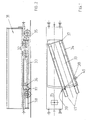
- Figure 3 depicts generally a freight wagon 1 commonly used on the railways, with a semi-trailer 2 loaded on it.
- Figure 4 depicts the same structure, in which the box 3 and the loadbearing side wall 4 fixedly adjoining it are indicated with dot-dashed lines in their position pivoted to the side, in which case a trailer can be driven onto the box along a driving bridge 28.
- the box 3 and the side wall 4 have been drawn with a continuous line in their closed position, which thus corresponds to Figure 3.
- the rest of the frame of the freight wagon, to which the wheels and the box with their side walls are secured, is in general indicated by reference numeral 5.
- the opening joint of the side wall, by which joint the box 3 is locked to the frame 5 for the duration of transport, is in general indicated by reference numeral 6, and the hinge device between the side wall 4 and the frame 5, about which hinge device the box 3 is pivoted to the side for loading and to inside the wagon 1 for transport, is indicated by reference numeral 7.
- the support boom according to the invention which is shown in Figure 3 in the transport position, turned under the side wall 4, and is depicted with dot-dashed lines in Figure 4 in the support position turned under the box 3, is indicated in general by reference numeral 8.
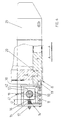
- Figure 5 depicts the structure of the support boom 8 and its articulation 9 to the frame 5 of the freight wagon.
- the support boom which is made up, for example, of an arm 29 having a box-like cross section and of an articulation casing 30 protruding from one of its ends, is locked so as to be immobile by means of latch devices 10, which are not depicted in greater detail.
- the articulation 9 is depicted in cross section. It comprises a vertical shaft secured to the freight-wagon frame 5, an articulation piece 12 being mounted on it inside the articulation casing 30 and being locked so as to be immobile by means of a fastening nut 13.
- a spring support 14 which comprises a ram 16 loaded by plate springs 15, for example, and a control nut 17.
- fastening means 21 for the support foot 22 adjustable in the vertical direction.
- Figure 6 shows how the articulation piece 12 is secured using horizontal pins 18 pivotably to the support boom 8 so that a pin-and-bushing structure is formed.
- the spring support 14 rests on the articulation piece 12 and is adjusted, for example by using a nut 17, to such a length D that the support boom 8 is in an approximately horizontal position when it is being pivoted about the articulation 9, i.e. about the vertical center line 42 of the shaft 11.
- the spring support 14 thus allows, when yielding, whereby its length D decreases, the transfer of the support boom under load from its horizontal position, without any damage to the articulation 9.
- Figure 6 also shows how the support boom 8, with a latch tappet 19 located on the outer wall of the articulation casing 30, locks the wedge joint 20 according patent application FI-882563 for example, between the side wall 4 and the freight-wagon frame 5.
- the latch devices 10 are at least approximately at the distance of the length L2 of the boom arm 29 from the articulation 9 and from the center line 42 of its pivot shaft.
- the latch tappet 19 for its part is at a small distance L1 from this center line 42.
- Figure 7 the arm 29 of the support boom 8 is turned outward, in which case it is under the box 3 pivoted to the side from the freight-wagon frame 5.
- the limiter 23 consists of a bar 43 articulated to the boom arm, one end of the bar being capable of sliding relative to the frame 5 as far as the stop 44.
- a support foot 22 At the outer end of the support-boom arm 29 there is a support foot 22.
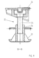
- Figure 8 depicts one structure for the adjustable support foot 22. It consists of a frame part 24, a leg fixedly installed in it, and a shoe 27 linked to the leg by a screw thread and adjustable by turning.
- the support foot 22 which is adjusted by means of a screw thread 26 to a suitable height so that the shoe 27 is pressed tightly against the ground, whereupon the support foot will support the outer end of the boom arm 29. Thereafter the box 3 can be pivoted normally to the loading/unloading position, in which the lower support surface 46 of the box bears on the upper surface 45 of the boom in order to support the box and the load.
- the horizontality of the boom arm 29 is adjusted by using the spring support 14, which at the same time enables the articulation 9 to yield in case the soil yields under the support foot 22.
- the articulation casing 30 of the boom is according to the invention mounted by means of pins 18 in the articulation piece 12 so that the pivot axis 47 is at least approximately horizontal and at least approximately perpendicular to the length L2 of the boom arm 29 and at distance H from the upper surface 45 of the boom arm 29.
- the spring support 14 is at distance S, which is greater than H, from the upper end 45 of the boom arm 29 and on the opposite side of the plane defined by the axes 42 and 47 than the boom arm 29, and between the articulation piece 12 and the articulation casing 30.
- the pivoting of the boom outward about the axis 42 is limited by a limiter 23 when the sliding means, e.g. a roller 48, of that bar 43 end which faces away from the boom arm 29 impinges against a stop 44, thus preventing greater projection of the boom.
- the roller 48 runs in slide bars 49 in the frame.
- the locking of the box 3 to the wagon frame is advantageously also by means of the boom 8.
- the boom When the boom is turned under the box 3 and the side wall 4 in their place in the frame 5, the boom serves as an effective lever the fulcrum of which is on the axis 42, and the working lever arm is the distance L1 of the latch tappet 19 from the axis 42, and the lever arm of the force is approximately the entire length L2 of the boom.
- the force closing the wedge joint 20 will be very high, since its magnitude will be L2/L1 x F, where force F is the pushing force effective at the end of the boom.
- This structure is especially suitable for closing a wedge joint according to previous patent application FI-882563, since it replaces the closing lever used in it.
- the boom 8 according to the invention can serve as the closing lever of any closing mechanism.
- the embodiment described has a single-arm lever, but a double-arm lever can also be construed, when necessary.
- latch means 10 which may per se be of any known type.
- the invention is not limited to the embodiment described above; numerous variants of the structure can be made.
- the spring support 14 can be placed on the same side of the plane of center lines 42 and 47 as the arm 29 when it is below the upper surface 45 of the arm.
- the spring support can also be placed on the boom arm side from the said plane, above the plane 45, or alternatively on that side of the said plane which faces away from the boom arm 29, below the plane 45.
- the positioning of the axis 42 and parts corresponding to it may considerably differ from that depicted in the lateral direction of the wagon.
- the positioning of the horizontal axis 47 and the parts associated with it can in the vertical direction differ considerably from that depicted, in which case it may be either above or below the planes 45, 46, depending on the rest of the wagon structure or on the space requirement.
- the axis 47 need not necessarily be perpendicular to the real center line of the boom arm 29, although this is usually preferable.
- the shaft 11 and the articulation piece 12, together with the bearings between them, are located inside the pivoting articulation casing, but a reverse structure is also conceivable in which the structural parts corresponding to the articulation casing and pivot pins 18 are placed inside the shaft 11, in which case the bearings are in a way formed between the outer surface of the articulation casing and the inside hole of the shaft 11.
- the spring support 14 is located so that its operating line is not horizontal as in the embodiment example but vertical, in which case it could, for example, be located on an extension parallel to the arm 29 on that side of the plane formed by the axes 42 and 47 which faces away from the arm 29. What is essential is that the arm 29 and the spring support form effective points for the forces of a lever the fulcrum of which is located on the axis 47.
Landscapes
- Engineering & Computer Science (AREA)
- Transportation (AREA)
- Mechanical Engineering (AREA)
- Forklifts And Lifting Vehicles (AREA)
- Jib Cranes (AREA)
Applications Claiming Priority (2)
| Application Number | Priority Date | Filing Date | Title |
|---|---|---|---|
| FI893060 | 1989-06-21 | ||
| FI893060A FI82650C (fi) | 1989-06-21 | 1989-06-21 | Stoedbom i ett transportmedel. |
Publications (3)
| Publication Number | Publication Date |
|---|---|
| EP0404037A2 true EP0404037A2 (de) | 1990-12-27 |
| EP0404037A3 EP0404037A3 (de) | 1991-03-27 |
| EP0404037B1 EP0404037B1 (de) | 1993-12-22 |
Family
ID=8528659
Family Applications (1)
| Application Number | Title | Priority Date | Filing Date |
|---|---|---|---|
| EP19900111493 Expired - Lifetime EP0404037B1 (de) | 1989-06-21 | 1990-06-19 | Stützträger in einem Transportfahrzeug |
Country Status (3)
| Country | Link |
|---|---|
| EP (1) | EP0404037B1 (de) |
| DE (1) | DE69005367T2 (de) |
| FI (1) | FI82650C (de) |
Cited By (2)
| Publication number | Priority date | Publication date | Assignee | Title |
|---|---|---|---|---|
| WO2006031178A1 (en) * | 2004-09-17 | 2006-03-23 | Je Utveckling O Förvaltning Ab | Railway wagon |
| WO2010120236A1 (en) | 2009-04-16 | 2010-10-21 | K Technology Ab | A railway wagon and a method of its loading |
Family Cites Families (1)
| Publication number | Priority date | Publication date | Assignee | Title |
|---|---|---|---|---|
| NL8501911A (nl) * | 1985-07-04 | 1987-02-02 | Fedde Walda Nanne Marcel Walda | Vier-buffer-druk-vergrendeling- en starmaak-inschuifbalken voor een dieplaadwagon met een draaibare vloer, alsmede een electrische aandrijving van de draaibare vloer. |
-
1989
- 1989-06-21 FI FI893060A patent/FI82650C/fi not_active IP Right Cessation
-
1990
- 1990-06-19 EP EP19900111493 patent/EP0404037B1/de not_active Expired - Lifetime
- 1990-06-19 DE DE1990605367 patent/DE69005367T2/de not_active Expired - Fee Related
Cited By (8)
| Publication number | Priority date | Publication date | Assignee | Title |
|---|---|---|---|---|
| WO2006031178A1 (en) * | 2004-09-17 | 2006-03-23 | Je Utveckling O Förvaltning Ab | Railway wagon |
| RU2356767C2 (ru) * | 2004-09-17 | 2009-05-27 | Йе Утвеклинг O Фервальтнинг Аб | Железнодорожный грузовой вагон |
| US7650844B2 (en) | 2004-09-17 | 2010-01-26 | Flexiwaggon Ab | Railway wagon |
| WO2010120236A1 (en) | 2009-04-16 | 2010-10-21 | K Technology Ab | A railway wagon and a method of its loading |
| CN102395501A (zh) * | 2009-04-16 | 2012-03-28 | K科技有限公司 | 铁路货车及其装载方法 |
| US8667902B2 (en) | 2009-04-16 | 2014-03-11 | K Technology Ab | Railway wagon and a method of its loading |
| EP2419312A4 (de) * | 2009-04-16 | 2014-08-06 | Technology Ab K | Schienenwaggon und verfahren zu seiner beladung |
| CN102395501B (zh) * | 2009-04-16 | 2014-09-24 | K科技有限公司 | 铁路货车及其装载方法 |
Also Published As
| Publication number | Publication date |
|---|---|
| FI893060A0 (fi) | 1989-06-21 |
| FI82650C (fi) | 1991-04-10 |
| EP0404037B1 (de) | 1993-12-22 |
| FI82650B (fi) | 1990-12-31 |
| DE69005367D1 (de) | 1994-02-03 |
| DE69005367T2 (de) | 1994-04-14 |
| EP0404037A3 (de) | 1991-03-27 |
Similar Documents
| Publication | Publication Date | Title |
|---|---|---|
| US4147266A (en) | Semi-trailer for handling and transporting standardized containers | |
| US4765792A (en) | Surface mounted truck leveler | |
| US6152674A (en) | Truck deck mounted cargo handling apparatus with ground level loading and unloading position | |
| US5460460A (en) | Scissors lift dock leveler | |
| CA1323390C (en) | Apparatus for rotation of tailgate assembly | |
| US5518354A (en) | Hook for actuating pull up hitch | |
| US3323158A (en) | Loading ramp construction | |
| US6164893A (en) | Self-contained and automatic chock for immobilization of vehicles and modular immobilization device utilizing these chocks | |
| US4456420A (en) | Car carrier having a sliding and tilting platform | |
| US5839864A (en) | Locking system for container-carrying trailer | |
| US5288197A (en) | Equipment trailer | |
| US2036344A (en) | Freight car for transporting vehicles | |
| US4375932A (en) | Powered cargo restraint | |
| US6068440A (en) | Locking mechanism for roll-off hoist | |
| US6205606B1 (en) | Vertically stored dock leveler | |
| US7278816B2 (en) | Locking mechanism for a double articulating hook lift apparatus usable mounted on a vehicle | |
| US4776735A (en) | Locking and stiffening means for a rail car with a rotatable loading floor | |
| US5109971A (en) | Pallet transport device | |
| US4227843A (en) | Device for coupling, transportation and placing of goods containers | |
| US4382735A (en) | Cargo securement device | |
| US5259718A (en) | Vehicle restraint | |
| EP0404037A2 (de) | Stützträger in einem Transportfahrzeug | |
| US5197782A (en) | Apparatus including a vehicle and a container for use in hauling and dumping material | |
| EP0344661B1 (de) | Radunterlegkeil | |
| US3528569A (en) | Unit load hold-down and releasing lift |
Legal Events
| Date | Code | Title | Description |
|---|---|---|---|
| PUAI | Public reference made under article 153(3) epc to a published international application that has entered the european phase |
Free format text: ORIGINAL CODE: 0009012 |
|
| AK | Designated contracting states |
Kind code of ref document: A2 Designated state(s): AT BE CH DE DK ES FR GB GR IT LI LU NL SE |
|
| PUAL | Search report despatched |
Free format text: ORIGINAL CODE: 0009013 |
|
| AK | Designated contracting states |
Kind code of ref document: A3 Designated state(s): AT BE CH DE DK ES FR GB GR IT LI LU NL SE |
|
| 17P | Request for examination filed |
Effective date: 19910419 |
|
| 17Q | First examination report despatched |
Effective date: 19930225 |
|
| GRAA | (expected) grant |
Free format text: ORIGINAL CODE: 0009210 |
|
| AK | Designated contracting states |
Kind code of ref document: B1 Designated state(s): DE FR GB |
|
| REF | Corresponds to: |
Ref document number: 69005367 Country of ref document: DE Date of ref document: 19940203 |
|
| ET | Fr: translation filed | ||
| PLBE | No opposition filed within time limit |
Free format text: ORIGINAL CODE: 0009261 |
|
| STAA | Information on the status of an ep patent application or granted ep patent |
Free format text: STATUS: NO OPPOSITION FILED WITHIN TIME LIMIT |
|
| 26N | No opposition filed | ||
| PGFP | Annual fee paid to national office [announced via postgrant information from national office to epo] |
Ref country code: FR Payment date: 19950630 Year of fee payment: 6 |
|
| PGFP | Annual fee paid to national office [announced via postgrant information from national office to epo] |
Ref country code: DE Payment date: 19960619 Year of fee payment: 7 |
|
| PG25 | Lapsed in a contracting state [announced via postgrant information from national office to epo] |
Ref country code: FR Effective date: 19970228 |
|
| REG | Reference to a national code |
Ref country code: FR Ref legal event code: ST |
|
| PG25 | Lapsed in a contracting state [announced via postgrant information from national office to epo] |
Ref country code: DE Free format text: LAPSE BECAUSE OF NON-PAYMENT OF DUE FEES Effective date: 19980303 |
|
| PGFP | Annual fee paid to national office [announced via postgrant information from national office to epo] |
Ref country code: GB Payment date: 19990601 Year of fee payment: 10 |
|
| PG25 | Lapsed in a contracting state [announced via postgrant information from national office to epo] |
Ref country code: GB Free format text: LAPSE BECAUSE OF NON-PAYMENT OF DUE FEES Effective date: 20000619 |
|
| GBPC | Gb: european patent ceased through non-payment of renewal fee |
Effective date: 20000619 |