EP0404143A1 - Schaltungsanordnung zur Überwachung von Wechselstromverbrauchern in Eisenbahnsignalanlagen - Google Patents
Schaltungsanordnung zur Überwachung von Wechselstromverbrauchern in Eisenbahnsignalanlagen Download PDFInfo
- Publication number
- EP0404143A1 EP0404143A1 EP19900111741 EP90111741A EP0404143A1 EP 0404143 A1 EP0404143 A1 EP 0404143A1 EP 19900111741 EP19900111741 EP 19900111741 EP 90111741 A EP90111741 A EP 90111741A EP 0404143 A1 EP0404143 A1 EP 0404143A1
- Authority
- EP
- European Patent Office
- Prior art keywords
- circuit
- current
- monitoring
- circuit arrangement
- relay
- Prior art date
- Legal status (The legal status is an assumption and is not a legal conclusion. Google has not performed a legal analysis and makes no representation as to the accuracy of the status listed.)
- Granted
Links
- 238000012544 monitoring process Methods 0.000 title claims abstract description 50
- 238000004804 winding Methods 0.000 claims description 20
- 230000005669 field effect Effects 0.000 claims description 7
- 230000005284 excitation Effects 0.000 claims description 6
- 230000000903 blocking effect Effects 0.000 claims 1
- 230000011664 signaling Effects 0.000 abstract 1
- 238000001514 detection method Methods 0.000 description 2
- 238000011156 evaluation Methods 0.000 description 2
- 238000005259 measurement Methods 0.000 description 2
- 238000012935 Averaging Methods 0.000 description 1
- 230000006978 adaptation Effects 0.000 description 1
- 239000003990 capacitor Substances 0.000 description 1
- 238000011161 development Methods 0.000 description 1
- 230000018109 developmental process Effects 0.000 description 1
- 230000000694 effects Effects 0.000 description 1
- 230000001939 inductive effect Effects 0.000 description 1
- 229920006395 saturated elastomer Polymers 0.000 description 1
- 230000036962 time dependent Effects 0.000 description 1
Images

Classifications
-
- B—PERFORMING OPERATIONS; TRANSPORTING
- B61—RAILWAYS
- B61L—GUIDING RAILWAY TRAFFIC; ENSURING THE SAFETY OF RAILWAY TRAFFIC
- B61L7/00—Remote control of local operating means for points, signals, or track-mounted scotch-blocks
- B61L7/06—Remote control of local operating means for points, signals, or track-mounted scotch-blocks using electrical transmission
- B61L7/08—Circuitry
- B61L7/10—Circuitry for light signals, e.g. for supervision, back-signalling
Definitions
- the invention relates to a circuit arrangement according to the preamble of patent claim 1.
- DE-OS 31 17 188 provides time-dependent components which, after the light signal current has been switched on, bring about increased magnetic excitation of the monitoring relay used as monitoring element for a certain time and in this way reduce the response threshold of the monitoring relay.
- DE-OS 31 40 559 discloses a circuit arrangement in which an additional current path switched on or off together with the day / night switchover ensures adaptation of the response and fallback values of the monitoring relay to the respective signal operating voltage.
- the known measures described above require a considerable amount of components.
- the components must be specially designed and dimensioned for the respective application (supply line length, consumer power).
- the invention is based on the object of specifying a simple monitoring circuit which is independent of the line length required in the individual case.
- the capacitive reactive current which has the mean value 0 within a half-wave of the supply voltage, does not contribute to the measurement.
- An inductive reactive current component caused by the inductance of the cable lead and the lamp transformer is so small at the frequencies (50 Hz) used in railway safety systems that it can be neglected compared to the active current and the capacitive reactive current.
- claim 2 provides a DC relay as a monitoring element, the excitation winding is bridged by a switch during each of the half-waves of the supply voltage by a switch. It therefore only detects active current half-waves of one polarity, the average of which responds. Active current half-waves of the other polarity flow via the parallel switch and do not influence the monitoring relay.
- both active current half-waves can be evaluated.
- the detection and averaging of the current is carried out separately for each half-wave because of the compensation of the reactive current component.
- both active current half-waves contribute to the excitation of the monitoring relay.
- Claims 4, 5 and 6 relate to the implementation of the switching device.
- it can consist of a transistor, which, arranged in the transverse branch of a rectifier bridge circuit, short-circuits voltages of any polarity that occur on the monitoring element as soon as it is controlled by a control circuit, in the simplest case a simple Schmitt trigger circuit.
- the switching device can also have two transistors corresponding to the polarities of the two voltages to be switched. So that a lower response threshold is achieved than with the circuit according to claim 4.
- MOS field effect transistors are used instead of conventional bipolar transistors, as in claim 6, a special control circuit can be saved and the inverse diodes of the MOS field effect transistors can be used as decoupling diodes.
- Claim 7 relates to an embodiment of the circuit arrangement according to the invention, which uses a monitoring transformer for decoupling between the consumer circuit and the monitoring circuit. Since the consumer current does not have to flow through the monitoring element here, the Switching device can also be arranged in series with the monitoring element.
- the circuit arrangement according to claim 7 is particularly suitable for solutions in which electronic circuits are used as monitoring elements instead of relays.
- FIG. 1 shows a signal lamp L which is supplied with the voltage U from an AC power source via a lamp transformer LT.
- the lamp transformer and the signal lamp are located in the outdoor area AA of a signal box, the power source is in the signal box ST itself.
- a feed cable of up to 7 km in length can be laid between the signal box and the lamp transformer.
- a monitoring circuit ÜS is arranged in the signal box, which detects and evaluates the current I flowing to the lamp transformer.
- the current I G measured at the location of the monitoring circuit is composed of an active current component I W and a reactive current component I B that is attributable to the capacity of the feed cable.
- This reactive current component continues to flow even after the lamp filament breaks and can thus simulate an intact signal lamp in the signal box, provided the total current I G is used for the evaluation.
- the switch S remains open only during one of the half-waves of the supply voltage U, it is closed during the other half-wave and thus bridges the winding of the monitoring relay with low resistance. Since, as can be seen from FIG. 1a, the supply voltage and the active current component are in phase with one another, the switch can be Control synchronously with the supply voltage using a simple control circuit.
- the reactive current components occurring during the half-wave of the active current flowing through the winding of the monitoring relay are compensated for, provided that the monitoring relay has sufficient inertia not to respond separately to the reactive current components occurring with twice the supply voltage frequency. With a DC relay, this condition will normally be present. By connecting capacitors in parallel to the relay winding, the inertia of the monitoring relay can be increased if necessary.
- the DC relay has two windings G I and G II , which are bridged by separate switches S1 and S2.
- the two switches are driven inversely to one another by the control circuit AS, so that the two active current half-waves influence different relay windings. Since the two oppositely wound relay windings are flowed through in opposite directions by the active current half-waves, both active current half-waves contribute in the same direction to the excitation of the monitoring relay.
- a monitoring circuit is shown with a transistor T as a switch.
- the transistor an ordinary bipolar transistor, is turned on by the control circuit AS during one of the half-waves of the supply voltage U and thus makes a diode bridge circuit BG which is responsible for the winding of the Monitoring relay G is in parallel, permeable to both polarities of the current I fed into the cable feed line.
- a monitoring circuit shown in FIG. 4 uses two transistors T1, T2 instead of a diode bridge circuit, to which diodes D1, D2 are connected in parallel in the reverse direction.
- the control by the control circuit AS takes place in parallel via current limiting resistors R1, R2.
- the circuit shown in FIG. 4 has a lower voltage drop than the circuit shown in FIG. 3.
- a particularly advantageous solution is represented by a circuit shown in FIG. 5, which essentially corresponds to the circuit shown in FIG. 4, but uses MOS field effect transistors FT1, FT2 instead of bipolar transistors.
- a current limiting resistor R3 and a Zener diode ZD are sufficient as a control circuit for limiting the controlling supply voltage.
- the inverse diodes ID1, ID2 integrated in the MOS field effect transistors can be used instead of the parallel diodes D1 and D2 in FIG. 4.
- the monitoring circuit is coupled to the consumer circuit via a monitor transformer UT.
- the voltage induced in the secondary winding of this transformer drives a current through a resistor R4.
- the voltage drop across the resistor R4, the Feed current is proportional, is evaluated by the monitoring element - here, for the sake of simplicity, a monitoring relay G is shown again.
- the switch S is here in series with the monitoring relay and interrupts its excitation circuit during those half-waves that are not to be evaluated.
- the switch can also be arranged parallel to the relay winding and short-circuit it.
Landscapes
- Engineering & Computer Science (AREA)
- Mechanical Engineering (AREA)
- Testing Of Short-Circuits, Discontinuities, Leakage, Or Incorrect Line Connections (AREA)
- Electric Propulsion And Braking For Vehicles (AREA)
- Train Traffic Observation, Control, And Security (AREA)
- Emergency Protection Circuit Devices (AREA)
Abstract
Description
- Die Erfindung betrifft eine Schaltungsanordnung gemäß dem Oberbegriff des Patentanspruchs 1.
- Beim Betrieb von Wechselstromverbrauchern, insbesondere Signallampen, in Eisenbahnsignalanlagen tritt bei längeren, zu den Verbrauchern führenden Kabelzuleitungen das Problem auf, daß die Wirkung der Kabelkapazität die Messung des durch den Verbraucher fließenden Stromes auf der Einspeiseseite der Kabelzuleitung verfälscht und damit eine Überwachung des Verbrauchers vom Stellwerk aus durch Messung des in die Kabelzuleitung fließenden Stromes erschwert.
- Vor allem dann, wenn für Signallampen eine Tag/Nacht-Umschaltung der Betriebsspannung vorgesehen ist, ist eine sichere Überwachung von über längere Zuleitungen gespeisten Signallampen oft nicht mehr möglich, da der bei Tagspannung über die Kabelkapazität fließende Blindstrom die Größenordnung des unterhalb des Wertes des bei Nachtspannung in die Kabelzuleitung fließenden Stromes liegenden Überwachungsschwellwertes erreicht.
- Es sind bereits eine Reihe von Überwachungsschaltungen bekannt, die das genannte Problem lösen: So sind in der DE-OS 31 17 188 zeitabhängig wirksame Bauelemente vorgesehen, welche nach Einschalten des Lichtsignalstromes für eine bestimmte Zeit eine erhöhte magnetische Erregung des als Überwachungselement eingesetzten Überwacherrelais herbeiführen und auf diese Weise die Ansprechschwelle des Überwacherrelais herabsetzen.
- In der DE-OS 31 40 559 ist eine Schaltungsanordnung offenbart, in der ein zusammen mit der Tag/Nacht-Umschaltung ein- oder ausgeschalteter Zusatzstrompfad für eine Anpassung der Ansprech- und Rückfallwerte des Überwacherrelais an die jeweilige Signal-Betriebsspannung sorgt.
- In der DE-PS 31 45 744, schließlich, wird der Kern eines Übertragers, über den das Überwacherrelais an den Lampenstromkreis angekoppelt ist, mit Ansprechen des Relais über eine Gleichstromwicklung teilgesättigt, um den Strom über die Wicklung des Überwachungsrelais abzusenken und damit dessen Rückfallen zu erleichtern.
- Die vorstehend beschriebenen, bekannten Maßnahmen erfordern einen erheblichen Bauelementeaufwand. Die Bauelemente müssen für den jeweiligen Einsatzfall (Zuleitungslänge, Verbraucherleistung) speziell ausgelegt und bemessen sein.
- Der Erfindung liegt die Aufgabe zugrunde, eine einfache Überwachungsschaltung anzugeben, die von der im Einzelfall benötigten Zuleitungslänge unabhängig ist.
- Eine Schaltungsanordnung, die diese Aufgabe löst, ist im Patentanspruch 1 beschrieben.
- Mit der Erfassung des Mittelwertes des in die Kabelzuleitung eingespeisten Stromes nur während einer der Halbwellen der Speisespannung wird nur der Wirkstromanteil dieses Stromes ausgewertet. Der kapazitive Blindstrom, der innerhalb einer Halbwelle der Speisespannung den Mittelwert 0 hat, trägt zur Messung nicht bei. Ein von der Induktivität der Kabelzuleitung und des Lampentransformators verursachter, induktiver Blindstromanteil ist bei den in Eisenbahnsicherungsanlagen benutzten Frequenzen (50 Hz) so klein, daß er gegenüber dem Wirkstrom und dem kapazitiven Blindstrom vernachlässigt werden kann.
- Weiterbildungen der Schaltungsanordnung nach der Erfindung sind in den Unteransprüchen wiedergegeben:
- So sieht Anspruch 2 ein Gleichstromrelais als Überwachungselement vor, dessen Erregerwicklung während jeweils einer der Halbwellen der Speisespannung von einem Schalter niederohmig überbrückt wird. Es erfaßt damit nur Wirkstromhalbwellen einer Polarität, auf deren Mittelwert es anspricht. Wirkstromhalbwellen der anderen Polarität fließen über den parallelliegenden Schalter und beeinflussen das Überwacherrelais nicht.
- Mit der in Anspruch 3 beschriebenen Ausgestaltung der erfindungsgemäßen Schaltungsanordnung können beide Wirkstromhalbwellen ausgewertet werden. Die Erfassung und Mittelung des Stromes erfolgt dabei wegen der Kompensation des Blindstromanteils für jede Halbwelle getrennt. Infolge gegensinniger Stromflußrichtungen in den Relaiswicklungen tragen jedoch beide Wirkstromhalbwellen zur Erregung des Überwacherrelais bei. Diese Anordnung hat gegenüber der im Anspruch 2 angegebenen Anordnung den Vorteil, daß sie für eine symmetrische Belastung der Speisestromquelle sorgt.
- Die Ansprüche 4, 5 und 6 betreffen die Realisierung der Schalteinrichtung. Sie kann im einfachsten Fall aus einem Transistor bestehen, der, im Querzweig einer Gleichrichter-Brückenschaltung angeordnet, am Überwachungselement auftretende Spannungen jeder Polarität kurzschließt, sobald er von einer Ansteuerschaltung, im einfachsten Fall einer einfachen Schmitt-Trigger-Schaltung, durchgesteuert wird.
- Die Schalteinrichtung kann auch, wie in Anspruch 5, zwei Transistoren entsprechend den Polaritäten der beiden zu schaltenden Spannungen aufweisen. Damit wird eine niedrigere Ansprechschwelle als mit der Schaltung nach Anspruch 4 erreicht.
- Werden, wie in Anspruch 6, anstelle gewöhnlicher Bipolar-Transistoren MOS-Feldeffekttransistoren verwendet, so kann eine besondere Ansteuerschaltung eingespart werden und als Entkopplungsdioden können die Inversdioden der MOS-Feldeffekttransistoren verwendet werden.
- Anspruch 7 betrifft eine Ausgestaltung der Schaltungsanordnung nach der Erfindung, die einen Überwachungstransformator zur Entkopplung zwischen Verbraucherstromkreis und Überwachungsstromkreis verwendet. Da hier der Verbraucherstrom nicht über das Überwachungselement fließen muß, kann die Schalteinrichtung auch in Reihe mit dem Überwachungselement angeordnet sein. Die Schaltungsanordnung nach Anspruch 7 eignet sich vor allem für Lösungen, in denen als Überwachungselemente anstelle von Relais elektronische Schaltungen verwendet werden.
- Anhand mehrerer Figuren sollen nun Ausfuhrungsbeispiele der Schaltungsanordnung nach der Erfindung beschrieben und ihre Funktion erklärt werden. Es zeigen:
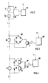
- Fig. 1 das Prinzip der Schaltungsanordnung nach der Erfindung,
- Fig. 1a Strom- und Spannungsverläufe,
- Fig. 2 Schaltung zur Auswertung beider Wirkstromhalbwellen,
- Fig. 3 eine Schaltungsanordnung mit einem Bipolar-Transistor als Schalter,
- Fig 4 eine Schaltungsanordnung mit zwei Bipolar-Transistoren als Schalter,
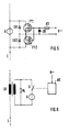
- Fig. 5 eine Schaltungsanordnung mit MOS-Feldeffekttransistoren als Schalter,
- Fig. 6 eine Schaltungsanordnung mit einem Überwachungstransformator.
- In Fig. 1 ist eine Signallampe L dargestellt, welche über einen Lampentransformator LT aus einer Wechselstromquelle mit der Spannung U gespeist wird.
- Hierbei befinden sich der Lampentransformator und die Signallampe in der Außenanlage AA eines Stellwerks, die speisende Stromquelle befindet sich im Stellwerk ST selbst. Zwischen Stellwerk und dem Lampentransformator kann ein Speisekabel von bis zu 7 km Länge verlegt sein.
- Um den einwandfreien Zustand der Signallampe L in der Außenanlage zu Überwachen, insbesondere einen eventuellen Bruch ihres Glühfadens festzustellen, ist im Stellwerk eine Überwachungsschaltung ÜS angeordnet, die den zum Lampentransformator fließenden Strom I erfaßt und auswertet.
- Nach Fig. 1a setzt sich der an der Stelle der Überwachungsschaltung gemessene Strom IG aus einem Wirkstromanteil IW und einem auf die Kapazität des Speisekabels zurückzuführenden Blindstromanteil IB zusammen. Dieser Blindstromanteil fließt auch nach Bruch des Lampenglühfadens weiter und kann so im Stellwerk eine intakte Signallampe vortäuschen, sofern zur Auswertung der Gesamtstrom IG verwendet wird.
- Die in Fig. 1 dargestellte Überwachungsschaltung, die aus einem Gleichstromrelais G als Überwacherrelais und einem die Wicklung dieses Gleichstromrelais Überbrückenden Schalter S besteht, ermöglicht es nun, zur Überwachung der Signallampe allein den Wirkstromanteil IW auszuwerten. Hierzu bleibt der Schalter S lediglich während einer der Halbwellen der Speisespannung U geöffnet, während der anderen Halbwelle wird er geschlossen und überbrückt damit die Wicklung des Überwacherrelais niederohmig. Da, wie aus Fig. 1a ersichtlich, Speisespannung und Wirkstromanteil miteinander phasengleich sind, läßt sich der Schalter mittels einer einfachen Ansteuerschaltung synchron mit der Speisespannung ansteuern. Die während der über die Wicklung des Überwacherrelais fließenden Halbwelle des Wirkstromes auftretenden Blindstromanteile kompensieren sich, sofern das Überwacherrelais genügend Trägheit aufweist, um nicht auf die mit doppelter Speisespannungsfrequenz auftretenden Blindstromanteile getrennt anzusprechen. Bei einem Gleichstromrelais wird diese Bedingung im Normalfall gegeben sein. Durch Parallelschalten von Kapazitäten zur Relaiswicklung läßt sich die Trägheit des Überwacherrelais, falls erforderlich, vergrößern.
- In Fig. 2 ist eine Schaltungsanordnung dargestellt, welche es gestattet, beide Wirkstromhalbwellen auszuwerten und damit jede Unsymmetrie bei der Belastung der Speisestromquelle durch die Signallampe zu vermeiden. In diesem Falle besitzt das Gleichstromrelais zwei Wicklungen GI und GII, welche von getrennten Schaltern S1 und S2 überbrückt sind. Die beiden Schalter werden von der Ansteuerschaltung AS invers zueinander angesteuert, so daß beide Wirkstromhalbwellen unterschiedliche Relaiswicklungen beeinflussen. Da die beiden gegensinnig gewickelten Relaiswicklungen von den Wirkstromhalbwellen zueinander gegensinnig durchflossen werden, tragen beide Wirkstromhalbwellen gleichsinnig zur Erregung des überwacherrelais bei.
- In Fig. 3 ist eine Überwachungsschaltung mit einem Transistor T als Schalter dargestellt. Der Transistor, ein gewöhnlicher Bipolar-Transistor, wird von der Ansteuerschaltung AS während einer der Halbwellen der Speisespannung U durchgesteuert und macht damit eine Dioden-Brückenschaltung BG, welche der Wicklung des Überwacherrelais G parallelliegt, für beide Polaritäten des in die Kabelzuleitung eingespeisten Stromes I durchlässig.
- Eine in Fig. 4 dargestellte Überwachungsschaltung verwendet anstelle einer Dioden-Brückenschaltung zwei Transistoren T1, T2, denen in Sperrichtung Dioden D1, D2 parallelgeschaltet sind. Die Ansteuerung durch die Ansteuerschaltung AS erfolgt parallel über Strombegrenzungswiderstände R1, R2. Die in Fig. 4 dargestellte Schaltung weist einen niedrigeren Spannungsabfall auf als die in Fig. 3 dargestellte Schaltung.
- Eine besonders vorteilhafte Lösung gibt eine in Fig. 5 dargestellte Schaltung wieder, die der in Fig. 4 dargestellten Schaltung im wesentlichen entspricht, jedoch anstelle von Bipolar-Transistoren MOS-Feldeffekttransistoren FT1, FT2 verwendet. Hier genugt als Ansteuerschaltung ein Strombegrenzungswiderstand R3 und eine Z-Diode ZD zur Begrenzung der Steuernden Speisespannung. Außerdem können anstelle der parallelliegenden Dioden D1 und D2 in Fig. 4 die in den MOS-Feldeffekttransistoren integrierten Inversdioden ID1, ID2 verwendet werden.
- In Fig. 6, schließlich, ist zur Erfassung und Auswertung des in die Kabelzuleitung zum Wechselstromverbraucher eingespeisten Stromes die Überwachungsschaltung über einen Überwacher-Transformtor ÜT an den Verbraucherstromkreis angekoppelt. Die in der Sekundärwicklung dieses Transformators induzierte Spannung treibt einen Strom über einen Widerstand R4. Die am Widerstand R4 abfallende Spannung, die dem Speisestrom proportional ist, wird vom Uberwachungselement - hier ist der Einfachheit halber wieder ein Überwacherrelais G dargestellt - ausgewertet. Der Schalter S liegt hier in Reihe mit dem Überwacherrelais und unterbricht dessen Erregerstromkreis während jener Halbwellen, die nicht ausgewertet werden sollen. Der Schalter kann jedoch auch, wie in Fig. 1, parallel zur Relaiswicklung angeordnet sein und diese kurzschließen.
Claims (7)
dadurch gekennzeichnet, daß das
Überwachungselement (G) auf den zeitlichen Mittelwert des es durchfließenden Stromes anspricht, daß eine synchron mit der Phase der Speisewechselspannung (U) angesteuerte Schalteinrichtung (S) vorgesehen ist, die das Überwachungselement (G) nur während der positiven oder nur während der negativen Halbwellen der Speisespannung in den Verbraucherstromkreis schaltet oder mit einem dem Verbraucherstrom proportionalen Signal beaufschlagt.
Applications Claiming Priority (2)
| Application Number | Priority Date | Filing Date | Title |
|---|---|---|---|
| DE3920430 | 1989-06-22 | ||
| DE3920430A DE3920430A1 (de) | 1989-06-22 | 1989-06-22 | Schaltungsanordnung zur ueberwachung von wechselstromverbrauchern in eisenbahnsignalanlagen |
Publications (2)
| Publication Number | Publication Date |
|---|---|
| EP0404143A1 true EP0404143A1 (de) | 1990-12-27 |
| EP0404143B1 EP0404143B1 (de) | 1994-09-14 |
Family
ID=6383315
Family Applications (1)
| Application Number | Title | Priority Date | Filing Date |
|---|---|---|---|
| EP90111741A Expired - Lifetime EP0404143B1 (de) | 1989-06-22 | 1990-06-21 | Schaltungsanordnung zur Überwachung von Wechselstromverbrauchern in Eisenbahnsignalanlagen |
Country Status (5)
| Country | Link |
|---|---|
| EP (1) | EP0404143B1 (de) |
| AT (1) | ATE111405T1 (de) |
| DE (2) | DE3920430A1 (de) |
| DK (1) | DK0404143T3 (de) |
| ES (1) | ES2063863T3 (de) |
Cited By (2)
| Publication number | Priority date | Publication date | Assignee | Title |
|---|---|---|---|---|
| DE4110990A1 (de) * | 1991-04-05 | 1992-10-08 | Standard Elektrik Lorenz Ag | Einrichtung zur pruefung von signallampen in eisenbahnanlagen |
| EP1524167A3 (de) * | 2003-10-14 | 2009-04-15 | Siemens Schweiz AG | Verfahren und Schaltungsanordnung zur Erzeugung einer eisenbahntechnisch sicheren Rückmeldung |
Families Citing this family (1)
| Publication number | Priority date | Publication date | Assignee | Title |
|---|---|---|---|---|
| DE202010013926U1 (de) | 2010-10-06 | 2012-01-11 | Bag Engineering Gmbh | Elektronisches Vorschaltgerät und Beleuchtungsgerät |
Citations (5)
| Publication number | Priority date | Publication date | Assignee | Title |
|---|---|---|---|---|
| DE2500412B2 (de) * | 1974-01-14 | 1976-03-04 | Philips Patentverwaltung Gmbh, 2000 Hamburg | Schaltungsanordnung zur ueberwachung von wechselstromkreisen |
| US3995262A (en) * | 1975-06-25 | 1976-11-30 | Welwyn Electric Limited | Electric lamp failure indicator circuit |
| DE3140559A1 (de) * | 1981-10-13 | 1983-04-28 | Standard Elektrik Lorenz Ag, 7000 Stuttgart | Schaltungsanordnung zum signaltechnisch sicheren betrieb von signallampen |
| DE3338490A1 (de) * | 1983-10-22 | 1985-05-02 | Standard Elektrik Lorenz Ag, 7000 Stuttgart | Schaltungsanordnung zur ueberwachung des betriebszustandes von in der aussenanlage eines stellwerks eingesetzten wechselstromverbrauchern |
| DE3813538A1 (de) * | 1988-04-22 | 1989-11-02 | Standard Elektrik Lorenz Ag | Schaltungsanordnung zum ueberwachten betrieb zweier wechselstromverbraucher ueber eine gemeinsame speiseleitung |
-
1989
- 1989-06-22 DE DE3920430A patent/DE3920430A1/de not_active Withdrawn
-
1990
- 1990-06-21 DK DK90111741.6T patent/DK0404143T3/da active
- 1990-06-21 EP EP90111741A patent/EP0404143B1/de not_active Expired - Lifetime
- 1990-06-21 ES ES90111741T patent/ES2063863T3/es not_active Expired - Lifetime
- 1990-06-21 AT AT90111741T patent/ATE111405T1/de not_active IP Right Cessation
- 1990-06-21 DE DE59007106T patent/DE59007106D1/de not_active Expired - Lifetime
Patent Citations (5)
| Publication number | Priority date | Publication date | Assignee | Title |
|---|---|---|---|---|
| DE2500412B2 (de) * | 1974-01-14 | 1976-03-04 | Philips Patentverwaltung Gmbh, 2000 Hamburg | Schaltungsanordnung zur ueberwachung von wechselstromkreisen |
| US3995262A (en) * | 1975-06-25 | 1976-11-30 | Welwyn Electric Limited | Electric lamp failure indicator circuit |
| DE3140559A1 (de) * | 1981-10-13 | 1983-04-28 | Standard Elektrik Lorenz Ag, 7000 Stuttgart | Schaltungsanordnung zum signaltechnisch sicheren betrieb von signallampen |
| DE3338490A1 (de) * | 1983-10-22 | 1985-05-02 | Standard Elektrik Lorenz Ag, 7000 Stuttgart | Schaltungsanordnung zur ueberwachung des betriebszustandes von in der aussenanlage eines stellwerks eingesetzten wechselstromverbrauchern |
| DE3813538A1 (de) * | 1988-04-22 | 1989-11-02 | Standard Elektrik Lorenz Ag | Schaltungsanordnung zum ueberwachten betrieb zweier wechselstromverbraucher ueber eine gemeinsame speiseleitung |
Cited By (2)
| Publication number | Priority date | Publication date | Assignee | Title |
|---|---|---|---|---|
| DE4110990A1 (de) * | 1991-04-05 | 1992-10-08 | Standard Elektrik Lorenz Ag | Einrichtung zur pruefung von signallampen in eisenbahnanlagen |
| EP1524167A3 (de) * | 2003-10-14 | 2009-04-15 | Siemens Schweiz AG | Verfahren und Schaltungsanordnung zur Erzeugung einer eisenbahntechnisch sicheren Rückmeldung |
Also Published As
| Publication number | Publication date |
|---|---|
| EP0404143B1 (de) | 1994-09-14 |
| DE3920430A1 (de) | 1991-01-03 |
| ATE111405T1 (de) | 1994-09-15 |
| DE59007106D1 (de) | 1994-10-20 |
| DK0404143T3 (da) | 1994-10-17 |
| ES2063863T3 (es) | 1995-01-16 |
Similar Documents
| Publication | Publication Date | Title |
|---|---|---|
| DE4339241C2 (de) | Schaltungsanordnung zur Überwachung und Erkennung des Ausfalls des Nulleiters oder eines Phasenleiters eines Drehstromnetzes | |
| DE4403375A1 (de) | Einrichtung und Verfahren zum Steuern eines induktiven Verbrauchers | |
| DE3527828C2 (de) | ||
| DE4005813A1 (de) | Vorrichtung zur ueberwachung des laststromes eines elektronisch geschalteten verbrauchers | |
| EP0608477A2 (de) | Halbleiterrelais | |
| DE3930091A1 (de) | Schaltungsanordnung zum schutz eines stromverbrauchers vor falschpolung seiner speisespannung | |
| EP0404143B1 (de) | Schaltungsanordnung zur Überwachung von Wechselstromverbrauchern in Eisenbahnsignalanlagen | |
| EP0009649B1 (de) | Schaltung zur Überwachung von Schaltzuständen | |
| DE1810707C3 (de) | Einrichtung zur Schalterstellungsanzeige in elektrischen Schaltanlagen | |
| DE3140559C2 (de) | ||
| EP0500201B1 (de) | Schaltung zum Überwachen wechselstromgespeister Signallampen | |
| DE4118346C1 (en) | Fuse monitoring circuit for three=phase network - has resistor star networks placed on each side of fuse and monitors current to determine faulty fuses | |
| DE3813538A1 (de) | Schaltungsanordnung zum ueberwachten betrieb zweier wechselstromverbraucher ueber eine gemeinsame speiseleitung | |
| EP0002504B1 (de) | Schaltungsanordnung zur Signalsicherung in Lichtsignalanlagen | |
| DE3644226C2 (de) | ||
| DE469386C (de) | Schaltung fuer selbsttaetige Streckenblockung | |
| DE3117188C2 (de) | Schaltungsanordnung zur Überwachung von Lichtsignalstromkreisen in Eisenbahnanlagen | |
| DD146782A3 (de) | Schaltungsanordnung zur staendigen ueberwachung von heizelementen | |
| DE4110990A1 (de) | Einrichtung zur pruefung von signallampen in eisenbahnanlagen | |
| DE1513585C (de) | Schaltungsanordnung zum Überwachen von zwei oder mehreren verschiedenen Wertigkei ten zugeordneten und/oder sich ausschließen den Lichtsignalen in Verkehrssignalanlagen | |
| DE2430180C2 (de) | Schaltungsanordnung zum Überwachen eines taktgesteuerten Triacs | |
| DE1808871B2 (de) | Vorrichtung zur verhuetung von einander ausschliessenden signalisierzustaenden | |
| DE2053377A1 (de) | Schaltungsanordnung zum eigensicheren Vergleich von logischen Verknüpfungssystemen in Eisenbahnsicherungsanlagen | |
| DE3025679A1 (de) | Ueberwachungseinrichtung fuer mit wechselstrom gespeiste verbraucher | |
| DE3540030A1 (de) | Anordnung zum ueberwachen eines elektrischen sicherungselementes |
Legal Events
| Date | Code | Title | Description |
|---|---|---|---|
| PUAI | Public reference made under article 153(3) epc to a published international application that has entered the european phase |
Free format text: ORIGINAL CODE: 0009012 |
|
| AK | Designated contracting states |
Kind code of ref document: A1 Designated state(s): AT BE CH DE DK ES FR GB GR IT LI LU NL SE |
|
| 17P | Request for examination filed |
Effective date: 19910214 |
|
| RAP3 | Party data changed (applicant data changed or rights of an application transferred) |
Owner name: ALCATEL SEL AKTIENGESELLSCHAFT |
|
| 17Q | First examination report despatched |
Effective date: 19931104 |
|
| RBV | Designated contracting states (corrected) |
Designated state(s): AT BE CH DE DK ES FR GB GR IT LI NL SE |
|
| GRAA | (expected) grant |
Free format text: ORIGINAL CODE: 0009210 |
|
| AK | Designated contracting states |
Kind code of ref document: B1 Designated state(s): AT BE CH DE DK ES FR GB GR IT LI NL SE |
|
| REF | Corresponds to: |
Ref document number: 111405 Country of ref document: AT Date of ref document: 19940915 Kind code of ref document: T |
|
| ITF | It: translation for a ep patent filed | ||
| REG | Reference to a national code |
Ref country code: DK Ref legal event code: T3 |
|
| REF | Corresponds to: |
Ref document number: 59007106 Country of ref document: DE Date of ref document: 19941020 |
|
| GBT | Gb: translation of ep patent filed (gb section 77(6)(a)/1977) |
Effective date: 19941006 |
|
| ET | Fr: translation filed | ||
| REG | Reference to a national code |
Ref country code: ES Ref legal event code: FG2A Ref document number: 2063863 Country of ref document: ES Kind code of ref document: T3 |
|
| EAL | Se: european patent in force in sweden |
Ref document number: 90111741.6 |
|
| REG | Reference to a national code |
Ref country code: GR Ref legal event code: FG4A Free format text: 3014247 |
|
| PLBE | No opposition filed within time limit |
Free format text: ORIGINAL CODE: 0009261 |
|
| STAA | Information on the status of an ep patent application or granted ep patent |
Free format text: STATUS: NO OPPOSITION FILED WITHIN TIME LIMIT |
|
| 26N | No opposition filed | ||
| PGFP | Annual fee paid to national office [announced via postgrant information from national office to epo] |
Ref country code: SE Payment date: 19970523 Year of fee payment: 8 |
|
| PGFP | Annual fee paid to national office [announced via postgrant information from national office to epo] |
Ref country code: DK Payment date: 19970526 Year of fee payment: 8 |
|
| PGFP | Annual fee paid to national office [announced via postgrant information from national office to epo] |
Ref country code: NL Payment date: 19970527 Year of fee payment: 8 |
|
| PGFP | Annual fee paid to national office [announced via postgrant information from national office to epo] |
Ref country code: GR Payment date: 19970530 Year of fee payment: 8 |
|
| PG25 | Lapsed in a contracting state [announced via postgrant information from national office to epo] |
Ref country code: DK Free format text: LAPSE BECAUSE OF NON-PAYMENT OF DUE FEES Effective date: 19980621 |
|
| PG25 | Lapsed in a contracting state [announced via postgrant information from national office to epo] |
Ref country code: SE Free format text: LAPSE BECAUSE OF NON-PAYMENT OF DUE FEES Effective date: 19980622 |
|
| PG25 | Lapsed in a contracting state [announced via postgrant information from national office to epo] |
Ref country code: GR Free format text: LAPSE BECAUSE OF NON-PAYMENT OF DUE FEES Effective date: 19980630 |
|
| PG25 | Lapsed in a contracting state [announced via postgrant information from national office to epo] |
Ref country code: NL Free format text: LAPSE BECAUSE OF NON-PAYMENT OF DUE FEES Effective date: 19990101 |
|
| EUG | Se: european patent has lapsed |
Ref document number: 90111741.6 |
|
| NLV4 | Nl: lapsed or anulled due to non-payment of the annual fee |
Effective date: 19990101 |
|
| REG | Reference to a national code |
Ref country code: DK Ref legal event code: EBP |
|
| PGFP | Annual fee paid to national office [announced via postgrant information from national office to epo] |
Ref country code: BE Payment date: 20000605 Year of fee payment: 11 |
|
| PGFP | Annual fee paid to national office [announced via postgrant information from national office to epo] |
Ref country code: ES Payment date: 20000622 Year of fee payment: 11 |
|
| PG25 | Lapsed in a contracting state [announced via postgrant information from national office to epo] |
Ref country code: ES Free format text: LAPSE BECAUSE OF NON-PAYMENT OF DUE FEES Effective date: 20010622 |
|
| PG25 | Lapsed in a contracting state [announced via postgrant information from national office to epo] |
Ref country code: BE Free format text: LAPSE BECAUSE OF NON-PAYMENT OF DUE FEES Effective date: 20010630 |
|
| BERE | Be: lapsed |
Owner name: ALCATEL SEL A.G. Effective date: 20010630 |
|
| REG | Reference to a national code |
Ref country code: GB Ref legal event code: IF02 |
|
| REG | Reference to a national code |
Ref country code: ES Ref legal event code: FD2A Effective date: 20030303 |
|
| PG25 | Lapsed in a contracting state [announced via postgrant information from national office to epo] |
Ref country code: IT Free format text: LAPSE BECAUSE OF NON-PAYMENT OF DUE FEES;WARNING: LAPSES OF ITALIAN PATENTS WITH EFFECTIVE DATE BEFORE 2007 MAY HAVE OCCURRED AT ANY TIME BEFORE 2007. THE CORRECT EFFECTIVE DATE MAY BE DIFFERENT FROM THE ONE RECORDED. Effective date: 20050621 |
|
| PGFP | Annual fee paid to national office [announced via postgrant information from national office to epo] |
Ref country code: AT Payment date: 20090615 Year of fee payment: 20 |
|
| PGFP | Annual fee paid to national office [announced via postgrant information from national office to epo] |
Ref country code: CH Payment date: 20090615 Year of fee payment: 20 |
|
| PGFP | Annual fee paid to national office [announced via postgrant information from national office to epo] |
Ref country code: DE Payment date: 20090619 Year of fee payment: 20 Ref country code: GB Payment date: 20090617 Year of fee payment: 20 |
|
| REG | Reference to a national code |
Ref country code: CH Ref legal event code: PL |
|
| REG | Reference to a national code |
Ref country code: GB Ref legal event code: PE20 Expiry date: 20100620 |
|
| PG25 | Lapsed in a contracting state [announced via postgrant information from national office to epo] |
Ref country code: GB Free format text: LAPSE BECAUSE OF EXPIRATION OF PROTECTION Effective date: 20100620 |
|
| PG25 | Lapsed in a contracting state [announced via postgrant information from national office to epo] |
Ref country code: DE Free format text: LAPSE BECAUSE OF EXPIRATION OF PROTECTION Effective date: 20100621 |
|
| PGFP | Annual fee paid to national office [announced via postgrant information from national office to epo] |
Ref country code: FR Payment date: 20090611 Year of fee payment: 20 |