EP0404155A2 - Appareil électronique portable avec un clavier - Google Patents
Appareil électronique portable avec un clavier Download PDFInfo
- Publication number
- EP0404155A2 EP0404155A2 EP90111771A EP90111771A EP0404155A2 EP 0404155 A2 EP0404155 A2 EP 0404155A2 EP 90111771 A EP90111771 A EP 90111771A EP 90111771 A EP90111771 A EP 90111771A EP 0404155 A2 EP0404155 A2 EP 0404155A2
- Authority
- EP
- European Patent Office
- Prior art keywords
- keyboard
- housing
- frame
- mounting portion
- fixing
- Prior art date
- Legal status (The legal status is an assumption and is not a legal conclusion. Google has not performed a legal analysis and makes no representation as to the accuracy of the status listed.)
- Granted
Links
Images


Classifications
-
- B—PERFORMING OPERATIONS; TRANSPORTING
- B03—SEPARATION OF SOLID MATERIALS USING LIQUIDS OR USING PNEUMATIC TABLES OR JIGS; MAGNETIC OR ELECTROSTATIC SEPARATION OF SOLID MATERIALS FROM SOLID MATERIALS OR FLUIDS; SEPARATION BY HIGH-VOLTAGE ELECTRIC FIELDS
- B03C—MAGNETIC OR ELECTROSTATIC SEPARATION OF SOLID MATERIALS FROM SOLID MATERIALS OR FLUIDS; SEPARATION BY HIGH-VOLTAGE ELECTRIC FIELDS
- B03C3/00—Separating dispersed particles from gases or vapour, e.g. air, by electrostatic effect
- B03C3/34—Constructional details or accessories or operation thereof
- B03C3/66—Applications of electricity supply techniques
-
- G—PHYSICS
- G06—COMPUTING OR CALCULATING; COUNTING
- G06F—ELECTRIC DIGITAL DATA PROCESSING
- G06F1/00—Details not covered by groups G06F3/00 - G06F13/00 and G06F21/00
- G06F1/16—Constructional details or arrangements
- G06F1/1613—Constructional details or arrangements for portable computers
- G06F1/1615—Constructional details or arrangements for portable computers with several enclosures having relative motions, each enclosure supporting at least one I/O or computing function
- G06F1/1616—Constructional details or arrangements for portable computers with several enclosures having relative motions, each enclosure supporting at least one I/O or computing function with folding flat displays, e.g. laptop computers or notebooks having a clamshell configuration, with body parts pivoting to an open position around an axis parallel to the plane they define in closed position
-
- B—PERFORMING OPERATIONS; TRANSPORTING
- B03—SEPARATION OF SOLID MATERIALS USING LIQUIDS OR USING PNEUMATIC TABLES OR JIGS; MAGNETIC OR ELECTROSTATIC SEPARATION OF SOLID MATERIALS FROM SOLID MATERIALS OR FLUIDS; SEPARATION BY HIGH-VOLTAGE ELECTRIC FIELDS
- B03C—MAGNETIC OR ELECTROSTATIC SEPARATION OF SOLID MATERIALS FROM SOLID MATERIALS OR FLUIDS; SEPARATION BY HIGH-VOLTAGE ELECTRIC FIELDS
- B03C3/00—Separating dispersed particles from gases or vapour, e.g. air, by electrostatic effect
- B03C3/34—Constructional details or accessories or operation thereof
- B03C3/40—Electrode constructions
- B03C3/45—Collecting-electrodes
-
- G—PHYSICS
- G06—COMPUTING OR CALCULATING; COUNTING
- G06F—ELECTRIC DIGITAL DATA PROCESSING
- G06F1/00—Details not covered by groups G06F3/00 - G06F13/00 and G06F21/00
- G06F1/16—Constructional details or arrangements
- G06F1/1613—Constructional details or arrangements for portable computers
- G06F1/1633—Constructional details or arrangements of portable computers not specific to the type of enclosures covered by groups G06F1/1615 - G06F1/1626
- G06F1/1662—Details related to the integrated keyboard
-
- H—ELECTRICITY
- H01—ELECTRIC ELEMENTS
- H01H—ELECTRIC SWITCHES; RELAYS; SELECTORS; EMERGENCY PROTECTIVE DEVICES
- H01H13/00—Switches having rectilinearly-movable operating part or parts adapted for pushing or pulling in one direction only, e.g. push-button switch
- H01H13/70—Switches having rectilinearly-movable operating part or parts adapted for pushing or pulling in one direction only, e.g. push-button switch having a plurality of operating members associated with different sets of contacts, e.g. keyboard
- H01H13/702—Switches having rectilinearly-movable operating part or parts adapted for pushing or pulling in one direction only, e.g. push-button switch having a plurality of operating members associated with different sets of contacts, e.g. keyboard with contacts carried by or formed from layers in a multilayer structure, e.g. membrane switches
-
- H—ELECTRICITY
- H01—ELECTRIC ELEMENTS
- H01H—ELECTRIC SWITCHES; RELAYS; SELECTORS; EMERGENCY PROTECTIVE DEVICES
- H01H2223/00—Casings
- H01H2223/002—Casings sealed
-
- H—ELECTRICITY
- H01—ELECTRIC ELEMENTS
- H01H—ELECTRIC SWITCHES; RELAYS; SELECTORS; EMERGENCY PROTECTIVE DEVICES
- H01H2223/00—Casings
- H01H2223/01—Mounting on appliance
- H01H2223/012—Snap mounting
-
- H—ELECTRICITY
- H01—ELECTRIC ELEMENTS
- H01H—ELECTRIC SWITCHES; RELAYS; SELECTORS; EMERGENCY PROTECTIVE DEVICES
- H01H2223/00—Casings
- H01H2223/01—Mounting on appliance
- H01H2223/014—Mounting on appliance located in recess
-
- H—ELECTRICITY
- H01—ELECTRIC ELEMENTS
- H01H—ELECTRIC SWITCHES; RELAYS; SELECTORS; EMERGENCY PROTECTIVE DEVICES
- H01H2223/00—Casings
- H01H2223/01—Mounting on appliance
- H01H2223/028—Mounting on appliance detachable
-
- H—ELECTRICITY
- H01—ELECTRIC ELEMENTS
- H01H—ELECTRIC SWITCHES; RELAYS; SELECTORS; EMERGENCY PROTECTIVE DEVICES
- H01H2231/00—Applications
- H01H2231/002—Calculator, computer
-
- H—ELECTRICITY
- H01—ELECTRIC ELEMENTS
- H01H—ELECTRIC SWITCHES; RELAYS; SELECTORS; EMERGENCY PROTECTIVE DEVICES
- H01H2239/00—Miscellaneous
- H01H2239/004—High frequency adaptation or shielding
Definitions
- the present invention relates to a portable electronic apparatus, and more particularly, to a portable electronic apparatus, such as a laptop personal computer, word processor, etc., having a keyboard at the front portion of a housing thereof.
- a laptop personal computer generally comprises a housing and a keyboard at the front portion thereof.
- the housing is formed integrally with a keyboard frame, which presses the peripheral edge portion of the keyboard body, thereby retaining the keyboard in the housing.
- Keys of the keyboard are arranged at the front portion of the housing so as to project from an opening of the keyboard frame.
- the printed board in the housing can be exposed by disengaging the keyboard and the keyboard frame from the front portion of the housing. If necessary, therefore, an extension memory, for example, can be easily additionally mounted in the housing without disassembling the whole housing.
- the keyboard frame can be formed from a low-priced resin material which can be plated. If the keyboard frame is damaged or considerably worn, moreover, the keyboard frame alone can be replaced with a new one.
- a large number of keys are mounted on the top of a rigid printed board having a circuit pattern, and a shielding plate is attached to the lower surface of the board.
- the shielding plate is used to prevent switching noises, attributable to key operation, from influencing the printed board in the housing, and its peripheral portion projects outward beyond the periphery of the printed board of the keyboard.
- the keyboard is attached to the front portion of the housing by superposing the projecting portion of the printed board on screw receiving bosses on the housing front and screwing them together from above. Also, screw receiving bosses integrally protrude downward from the inside of each frame portion of the keyboard frame, and the frame is attached to the housing front by means of screws threadedly passed through the bosses from under the housing.
- the keyboard is inevitably large-sized, however, since the shielding plate has the projecting portion on its periphery, in order to allow the keyboard, including the printed board which cannot be provided with any screw receiving portion, to be attached to the housing. Since the screw receiving bosses are arranged on the inside of each frame portion of the keyboard frame, moreover, the individual frame portions have a great width, so that the keyboard frame is large-sized. In the conventional portable electronic apparatus, therefore, the keyboard including its surroundings is bulky, so that the whole housing is large-sized.
- the present invention has been contrived in consideration of these circumstances, and its object is to provide a portable electronic apparatus permitting miniaturization.
- a portable electronic apparatus comprises: a housing having a mounting portion; a keyboard unit removably mounted on the mounting portion, the keyboard unit including a substantially planar keyboard body made of synthetic resin, a large number of keys arranged substantially over the whole top face of the keyboard body, a film member put on the underside of the keyboard body and having a circuit pattern thereon, and a keyboard frame fitted on the peripheral edge portion of the keyboard body, the keyboard frame being fitted in the housing, the keyboard body having a fixing portion protruding from the underside thereof so as to extend through the film member; and means for fixing the fixing portion to the housing.
- the keyboard body is fitted inside the keyboard frame for unification.
- the keyboard body and the keyboard frame are connected in the following manner.
- a plurality of engaging hooks, which are formed on the keyboard frame are caused to engage the underside of the edge portions of the keyboard body by passing the hooks through their corresponding notches in the keyboard body.
- the lower surface of the inner peripheral wall portion of the keyboard frame is caused to abut against the upper surface of the peripheral edge portion of the keyboard body.
- the peripheral edge portion of the keyboard body is vertically held between the inner peripheral wall portion of the frame and the engaging hooks from both sides.
- the keyboard frame is fitted into the housing, so that the keyboard unit, including the keyboard body and the keyboard frame connected to each other, is temporarily assembled to the mounting portion of the housing.
- the assembled keyboard unit is fixed to the housing as the fixing portion, integrally formed on the keyboard body, is fixed to the housing by means of the screwing means.
- the keyboard frame need not be provided with any fixing portion such as screw receiving bosses, so that each frame portion can be reduced in size.
- the fixing portion can be formed integrally with the body.
- the fixing portion can be arranged without forming any projecting portion which protrudes from the peripheral edge of the keyboard body, so that the keyboard itself can be made small-sized.
- Figs. 1 to 15 show a laptop personal computer according to an embodiment of the present invention, in which:
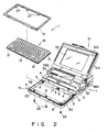
- the computer comprises a plastic housing 1 having a substantially rectangular plane configuration.
- the housing 1 includes a base portion 2 having an entirely open top and a cover portion 3 screwed to the base portion 2 so as to cover the rear half thereof.
- the base portion 2 includes a substantially rectangular bottom wall 2a and a peripheral wall 2b protruding therefrom and extending along the peripheral edge of the bottom wall.
- the housing 1 contains therein a printed board 36 (mentioned later) mounted with electronic parts, a floppy disk drive unit (not shown), etc.
- a front end wall 3a of the cover portion 3 extends substantially perpendicular to the bottom wall 2a of the base portion 2, and engaging portions 4 (see Figs. 2 and 11) are formed at a plurality of positions of the lower part of the wall 3a.
- each engaging portion 4 is formed of a recess cut in the lower edge of the front end wall 3a.
- the engaging portion 4 may be formed of a hole or a forwardly opening recess.
- the front portion of the peripheral wall 2b of the base portion 2 situated corresponding to the front half of the base portion, constitutes a front peripheral wall of the housing 1.
- the front peripheral wall and the front end wall 3a define a mounting portion 10 having an entirely open top for receiving a keyboard unit 11 mentioned later.
- the printed board 36 is disposed on the bottom wall 2a so as to face the opening of the mounting portion 10.
- a shielding film 37 is interposed between the board 36 and the bottom wall 2a.
- the film 37 which is connected to a circuit ground of the computer, serves to shield the board 36 from noises from outside the housing 1.
- the front end wall 3a integrally includes a plurality of connecting portions 5 which protrude forward from the lower end of the wall 3a. These connecting portions 5 are put on their corresponding screw receiving projections 6 which protrude from the bottom wall 2a of the base portion 2.
- a nut 7 is inserted in each projection 6, and each connecting portion 5 is fixed to the base portion 2 by means of a screw 8 screwed into its corresponding nut 7 from above through the connecting portion 5.
- the connecting portions 5 are used to support a rear frame portion 13d of a keyboard frame 13 (mentioned later) from below.
- Three projections 9 are integrally formed on the front end portion of the bottom wall 2a of the base portion 2. Each projection 9 has a through hole through which a screw 22 for fixing the keyboard unit 11 is passed.
- the keyboard unit 11 is removably attached to the mounting portion 10 of the housing 1 so as to close the top opening thereof.
- the unit 11 includes a keyboard 12 and the keyboard frame 13 surrounding the peripheral edge portion of the keyboard.
- the keyboard 12 includes a keyboard body 14, a large number of keys 15, a film 16, and a shielding plate 17.
- the keyboard body 14 is in the form of a flat plastic plate having a rectangular plane configuration.
- the keys 15 are arranged substantially over the whole top face of the keyboard body 14.
- a protuberant face bar 12a is integrally formed on the top face of the keyboard body 14 so as to divide standard keys and function keys.
- the film 16 is put on the underside of the keyboard body 14 so as to cover the whole area thereof, and is formed having a circuit pattern used to guide switching input by means of key operation.
- the shielding plate 17 serves to prevent switching noises produced by the key operation from influencing the printed board 36 in the housing 1.
- the shielding plate 17, which is substantially equal to the keyboard body 14 in size, is fixed to the underside of the body 14 so that the film 16 is sandwiched between the plate 17 and the body 14.
- the shielding plate 17 and the film 16 are fixed to the keyboard body 14 by means of a plurality of screws 20 for keyboard assembly, which are passed through the two layers to be threadedly engaged with the body 14.
- Some portions of the shielding plate 17 are cut and bent to form L-shaped bent portions 17a. Each bent portion 17a covers the rear face and bottom face of its corresponding screw receiving boss 18.
- a plurality of notches 21 are cut in the peripheral edge portion of the rectangular plate structure of the keyboard 12.
- each screw receiving boss 18 of the keyboard 12 constructed in this manner is threadedly engaged with a screw 22 which is passed through its corresponding screw passage projection 9 and the bottom portion of its corresponding bent portion 17a, from under the bottom wall 2a of the housing 1.
- the keyboard 12 can be fixed to the mounting portion 10 of the housing 1 by tightening the screws 22.
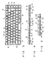
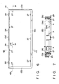
- the keyboard frame 13 is a rectangular frame formed of synthetic resin such as ABS resin, and its details are shown in Figs. 6 to 9.
- the frame 13 has a fitting groove 25 which is continuously formed along a front frame portion 13a and two opposite lateral frame portions 13b and 13c thereof.
- a rear frame portion 13d of the keyboard frame 13 abuts against the whole surface of the front end wall 3a of the cover portion 3, and the fitting groove 25 is in engagement with the front peripheral wall of the base portion 2. In this state, the rear frame portion 13d rests on the connecting portions 5.
- the keyboard frame 13 is provided with an annular inner peripheral wall 26 which constitutes its inner circumferential surface.
- the inner peripheral wall 26 is formed having size and shape such that its lower edge 26a engages the upper surface of the peripheral edge portion of the keyboard body 14, just outside the keys 15.
- a plurality of engaging hooks 27 integrally protrude downward from the inner peripheral wall 26, corresponding to the notches 21.
- Each hook 27 is designed so as to be passed through its corresponding notch 21 to engage the lower surface of the peripheral edge portion of the keyboard 12.
- Each engaging hook 27 is at a vertical distance A from the lower edge 26a of the inner peripheral wall 26.
- the distance A is substantially equivalent to the thickness of the plate structure of the keyboard 12, that is, the thickness of the combination of the keyboard body 14, film 16, and shielding plate 17.
- the keyboard 12 is fitted inside the keyboard frame 13 for unification so that its peripheral edge portion is held between the engaging hooks 27 and the lower edge 26a of the inner peripheral wall 26.
- a plurality of engaging projections 28 protrude rearward from the rear face of the rear frame portion 13d of the keyboard frame 13. These projections 28 are fitted in their corresponding engaging portions 4 of the front end wall 3a. As the engaging projections 28 and the engaging portions 4 thus engage one another, the rear frame portion 13d of the keyboard frame 13 is fixed to the housing 1.
- the keyboard 12 and the keyboard frame 13 are united to form the keyboard unit 11.
- the engaging hooks 27 protruding from the inner periphery of the keyboard frame 13 are passed through their corresponding notches 21 of the keyboard 12 in a manner such that the frame 13 is somewhat elastically deformed.
- the keyboard 12 is fitted into the keyboard frame 13.
- the engaging hooks 27 passed through the notches 21 engage the lower surface of the peripheral edge portion of the keyboard 12, and at the same time, the lower edge 26a of the inner peripheral wall 26 of the keyboard frame 13 abuts against the upper surface of the peripheral edge portion of the keyboard 12.
- the peripheral edge portion of the keyboard 12 is vertically held between the inner peripheral wall 26 and the engaging hooks 27 from both sides, so that the keyboard 12 and the keyboard frame 13 can be connected to each other without using any screws or the like.
- the keyboard unit 11 is temporarily assembled to the mounting portion 10 of the housing 1.
- the engaging projections 28 of the keyboard frame 13 are first fitted into the engaging portions 4 of the front end wall 3a of the cover portion 3, and the rear frame portion 13d of the frame 13 is caused to abut against the wall 3a.
- the lower edge of the rear frame portion 13d is put on the connecting portions 5 of the front end wall 3a.
- the upper end portion of the front peripheral wall of the base portion 2 of the housing 1 is fitted in the fitting groove 25, which extends along the lateral frame portions 13b and 13c and the front frame portion 13a of the keyboard frame 13.
- the keyboard unit 11 is temporarily assembled to the mounting portion 10 of the housing 1, thereby closing the opening which covers the whole area of the front top face of the housing 1, that is, the opening of the mounting portion.
- the assembled keyboard unit 11 is fixed to the housing 1. More specifically, the screws 22 are passed through their corresponding screw passage projections 9 of the base portion 2 from under the same, and are threadedly engaged with their corresponding screw receiving bosses 18 which integrally protrude from the underside of the keyboard body 14.
- the keyboard unit 11 is fixed to the mounting portion 10 of the housing 1 by means of the tightening force of the screws 22.
- the shielding plate 17 of the keyboard 12 is connected electrically with the shielding film 37 on the housing side by means of the bent portions 17a. Accordingly, the plate 17 can be connected electrically to the circuit ground on the housing side through the film 37 by only attaching the unit 11 to the housing 1.
- the keyboard and its surroundings can be disassembled by inversely following the aforementioned steps of procedure.
- a display unit 31 is rockably mounted on the cover portion 3 of the housing 1.
- the unit 31 includes a flat panel display 33, such as a liquid crystal display, an outer cover 31a enclosing the back of the display 33, and an inner cover 31b having a display window.
- the unit 31 has a pair of legs 38a and 38b, which are inserted in their corresponding recesses 32 in the upper surface of the cover portion 3 of the housing 1, and are rockably supported by means of hinges mentioned later.
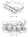
- the display unit 31 can rock between an open position shown in Fig. 1, where it allows an operator to operate the keyboard 12 while observing the display 33, and a closed position shown in Fig. 12, where it conceals the keyboard 12.
- the display unit 31 is designed so that the upper surface of the outer cover 31a is continuous and flush with that of the cover portion 3 of the housing 1 when in the closed position.
- numerals 34 and 35 denote, respectively, a removable battery pack and a removable optional cover which is used to cover an expected arrangement region for optional parts.
- the respective upper surfaces of the pack 34 and the cover 35 are continuous and flush with that of the cover portion 3.
- a pair of hinges 40 are incorporated in each leg 38a of the display unit 31. These hinges 40 serve not only to support the unit 31 for rocking motion, but also to keep the unit 31 at any desired open angle. Since the two hinges 40 have the same construction, only one of them will be described in detail below.
- the hinge 40 is provided with a bracket 42, which is fixed to a pair of bosses 43 on the inside of the outer cover 31a by means of screws 44.
- the bracket 42 has a pair of bearing walls 46a and 46b facing each other, and a through hole 47 is bored through each bearing wall.
- a rotating shaft 48 is rotatably passed through the holes 47.
- a screw 51 is screwed on one end of the shaft 48 with the aid of a plain washer 49 and a spring washer 50, whereby the shaft 48 is prevented from coming off the bracket 42.
- the rotating shaft 48 is a stepped shaft having a small-diameter portion 48a and a large-diameter portion 48b.
- a plain washer 52 with an outer diameter greater than the large-diameter portion is fitted on the small-diameter portion.
- a stepped portion between the large- and small-diameter portions 48a and 48b is situated close to the bearing wall 46a, and the washer 52 abuts against this stepped portion.
- wave washers 54 for use as ring-shaped spring members, e.g., two in number, are mounted on the small-diameter portion 48a so as to be situated between the bearing wall 46a and the plain washer 52.
- the washers 54 are axially compressed between the wall 46a and the washer 52 by means of the clamping force of the screw 51.
- a frictional force is produced between the wall 46a and the washer 52, that is, between the bracket 42 and the rotating shaft 48, by the action of the wave washers 54. This frictional force serves to restrain relative rotation of the bracket 42 and the shaft 48.
- the other end portion of the rotating shaft 48 projects into the inside space of the cover portion 3, penetrating the wall of the leg 38a and a wall defining the recess 32.
- a rectangular stopper portion 56 is formed at the projecting end portion of the shaft 48.
- the stopper portion 56 is nonrotatably fitted in a rectangular hole 58 of a receiving fitment 57, which is fixed to the inside of the cover portion 3.
- the bracket 42 When the display unit 31 is rocked from its closed position to a desired open position, the bracket 42, fixed on the display unit side, rocks around the outer circumferential surface of the rotating shaft 48.
- the two wave washers 54 are interposed between the washer 52 on the shaft 48 and the bearing wall 46a of the bracket 42. Accordingly, the washers 54 are pressed against both the wall 46a and the washer 52 to produce the frictional force between them. This frictional force restrains the bracket 42 and the rotating shaft 48 from rocking relatively to each other, so that the display unit 31 can be kept fixed at the desired open position.
- the keyboard frame 13 is pressed against the front peripheral edge of the base portion 2, through the engagement between the keyboard body 14 and the engaging hooks 27, as the screws 22 for fixing the keyboard 12 are tightened.
- the rear frame portion 13d of the keyboard frame 13 is attached to the mounting portion 10 so that it is prevented from slipping off upward by the engagement between the engaging projections 28 and the engaging portions 4.
- the keyboard frame 13 need not be provided with screw receiving bosses or the like for fixing the frame 13 to the housing 1.
- the frame portions 13a to 13c of the keyboard frame 13 can be reduced in width, so that the whole frame can be miniaturized.
- the keyboard 12 is constructed including the plastic keyboard body 14 and the film 16 with the circuit pattern on the underside thereof, instead of using a printed board.
- the screw receiving bosses 18 can be integrally formed on the plastic body 14. Accordingly, the shielding plate 17 need not be provided with any fixing portion for fixing the keyboard 12 to the housing 1, and therefore, can be formed having substantially the same size as the keyboard body 14. Thus, the keyboard 12 can be miniaturized.
- the whole apparatus can be made small-sized.
- the shielding plate 17 of the keyboard 12 is connected electrically with the shielding film 37 on the housing side by means of the bent portions 17a. Accordingly, the plate 17 can be connected electrically to the circuit ground on the housing side through the film 37 by only attaching the unit 11 to the housing 1. Thus, there is no need of providing any exclusive-use connecting circuit for connecting the shielding plate 17 and the circuit ground, so that the construction and assembly of the apparatus can be simplified.
- the present invention is not limited to the portable electronic apparatus of the type described in connection with the above embodiment, and may be also applied to any other suitable electronic apparatuses, such as those portable electronic apparatuses whose display unit is not collapsible.
Landscapes
- Engineering & Computer Science (AREA)
- Computer Hardware Design (AREA)
- Theoretical Computer Science (AREA)
- Physics & Mathematics (AREA)
- Human Computer Interaction (AREA)
- General Engineering & Computer Science (AREA)
- General Physics & Mathematics (AREA)
- Mathematical Physics (AREA)
- Input From Keyboards Or The Like (AREA)
- Casings For Electric Apparatus (AREA)
- Shielding Devices Or Components To Electric Or Magnetic Fields (AREA)
Applications Claiming Priority (2)
| Application Number | Priority Date | Filing Date | Title |
|---|---|---|---|
| JP162217/89 | 1989-06-23 | ||
| JP1162217A JP2763137B2 (ja) | 1989-06-23 | 1989-06-23 | キーボードユニットおよびこのキーボードユニットを備えた小形電子機器 |
Publications (3)
| Publication Number | Publication Date |
|---|---|
| EP0404155A2 true EP0404155A2 (fr) | 1990-12-27 |
| EP0404155A3 EP0404155A3 (fr) | 1991-08-28 |
| EP0404155B1 EP0404155B1 (fr) | 1997-05-14 |
Family
ID=15750192
Family Applications (1)
| Application Number | Title | Priority Date | Filing Date |
|---|---|---|---|
| EP90111771A Expired - Lifetime EP0404155B1 (fr) | 1989-06-23 | 1990-06-21 | Appareil électronique portable avec un clavier |
Country Status (5)
| Country | Link |
|---|---|
| US (1) | US5483418A (fr) |
| EP (1) | EP0404155B1 (fr) |
| JP (1) | JP2763137B2 (fr) |
| KR (1) | KR930005794B1 (fr) |
| DE (1) | DE69030687T2 (fr) |
Cited By (5)
| Publication number | Priority date | Publication date | Assignee | Title |
|---|---|---|---|---|
| WO1994018686A1 (fr) * | 1993-02-03 | 1994-08-18 | A-Dec, Inc. | Panneau de commande a clavier scelle |
| US5402311A (en) * | 1991-10-11 | 1995-03-28 | Kabushiki Kaisha Toshiba | Electronic apparatus having heat sink for cooling circuit component |
| US5519585A (en) * | 1993-04-12 | 1996-05-21 | Dell Usa, L.P. | Sandwiched insulative/conductive layer EMI shield structure for printed circuit board |
| WO2003037684A1 (fr) * | 2001-10-26 | 2003-05-08 | Leopold Kostal Gmbh & Co. Kg | Dispositif pour couvrir un element de fixation et dispositif de commande destine a etre fixe sur un module |
| WO2014164470A1 (fr) * | 2013-03-11 | 2014-10-09 | Google Inc. | Boîtier d'ordinateur portable et procédés d'assemblage |
Families Citing this family (33)
| Publication number | Priority date | Publication date | Assignee | Title |
|---|---|---|---|---|
| US5953206A (en) * | 1997-10-15 | 1999-09-14 | Hewlett-Packard Company | Thermal dissipation and EMI shielding structure for notebook computers |
| US6377246B1 (en) * | 1998-01-16 | 2002-04-23 | Lucent Technologies Inc. | Article comprising a computer-style keyboard |
| KR200215120Y1 (ko) | 1998-12-01 | 2001-03-02 | 윤종용 | 휴대형 컴퓨터 |
| US6341061B1 (en) * | 1999-12-28 | 2002-01-22 | International Business Machines Corporation | Standup notebook computer |
| AU2001275627A1 (en) * | 2000-07-19 | 2002-02-05 | Katz, Michael | Folding cellular telephone and digital assistant with improved keyboard |
| JP2002149305A (ja) * | 2000-10-25 | 2002-05-24 | Internatl Business Mach Corp <Ibm> | 情報端末、そのキーボードユニット及びシステムユニット |
| JP4233086B2 (ja) * | 2003-03-11 | 2009-03-04 | 株式会社東芝 | 電子機器 |
| JP2005070969A (ja) * | 2003-08-21 | 2005-03-17 | Toshiba Corp | 電子機器および電子機器に用いる操作ユニット |
| JP2005108711A (ja) * | 2003-09-30 | 2005-04-21 | Toshiba Corp | 電池ユニットおよび電力供給制御方法 |
| JP2005157789A (ja) * | 2003-11-26 | 2005-06-16 | Toshiba Corp | 電子機器 |
| JP2005346185A (ja) * | 2004-05-31 | 2005-12-15 | Toshiba Corp | 電子機器 |
| JP4533712B2 (ja) * | 2004-09-30 | 2010-09-01 | 株式会社東芝 | 電子機器 |
| JP2006099550A (ja) * | 2004-09-30 | 2006-04-13 | Toshiba Corp | 電子機器 |
| JP4799350B2 (ja) * | 2006-09-29 | 2011-10-26 | 株式会社東芝 | 電子機器 |
| TWM312103U (en) * | 2006-11-24 | 2007-05-11 | Quanta Comp Inc | Connection strucutre |
| US8132975B2 (en) * | 2007-04-13 | 2012-03-13 | Hewlett-Packard Development Company, L.P. | Keyboard stiffening system |
| JP4869181B2 (ja) * | 2007-08-27 | 2012-02-08 | 三洋電機株式会社 | 放熱構造を有する携帯機器 |
| JP4421663B1 (ja) * | 2008-09-10 | 2010-02-24 | 株式会社東芝 | プリント配線板、電子機器 |
| JP4489133B2 (ja) * | 2008-09-10 | 2010-06-23 | 株式会社東芝 | プリント配線板、電子機器 |
| JP2010067194A (ja) * | 2008-09-12 | 2010-03-25 | Fujitsu Ltd | 電子機器 |
| JP4489135B1 (ja) * | 2008-12-26 | 2010-06-23 | パナソニック株式会社 | 携帯電子機器 |
| JP2010231552A (ja) * | 2009-03-27 | 2010-10-14 | Nec Personal Products Co Ltd | キーボードユニットおよび携帯型情報処理装置 |
| CN102053663A (zh) * | 2009-11-02 | 2011-05-11 | 鸿富锦精密工业(深圳)有限公司 | 便携式计算机及其键盘 |
| JP5728949B2 (ja) * | 2011-01-06 | 2015-06-03 | 富士通株式会社 | 第2装置 |
| US9128532B2 (en) | 2012-09-28 | 2015-09-08 | Hewlett-Packard Development Company, L.P. | Keyboard with screw nut |
| US9086852B2 (en) * | 2012-12-21 | 2015-07-21 | Intel Corporation | Fastening techniques for electronic devices |
| US9149100B2 (en) | 2013-08-07 | 2015-10-06 | ACCO Brands Corporation | Case for a portable electronic device |
| US8861191B1 (en) | 2013-09-30 | 2014-10-14 | Google Inc. | Apparatus related to a structure of a base portion of a computing device |
| US8811003B1 (en) * | 2013-09-30 | 2014-08-19 | Google Inc. | Keyboard support member for a computing device |
| RU2595969C1 (ru) * | 2015-04-29 | 2016-08-27 | Федеральное государственное унитарное предприятие "Научно-производственный центр "Дельта" (ФГУП "НПЦ "Дельта") | Клавиатура экранированная |
| CN107863263A (zh) * | 2017-12-08 | 2018-03-30 | 武汉浩宏科技有限公司 | 一种按键组件 |
| US11086366B2 (en) * | 2019-09-05 | 2021-08-10 | Microsoft Technology Licensing, Llc | User-serviceable dimensionally-constrained device |
| TWI857755B (zh) * | 2023-08-18 | 2024-10-01 | 宏碁股份有限公司 | 具快拆鍵盤的筆記型電腦 |
Family Cites Families (17)
| Publication number | Priority date | Publication date | Assignee | Title |
|---|---|---|---|---|
| US4035794A (en) * | 1975-11-19 | 1977-07-12 | Harris Corporation | Radiation suppressed keyboard |
| US4333155A (en) * | 1979-05-18 | 1982-06-01 | Litton Business Systems, Inc. | Calculator having a modular keyboard |
| US4323979A (en) * | 1979-08-20 | 1982-04-06 | Litton Business Systems, Inc. | Cartridge and bezel assembly for a calculator |
| US4467150A (en) * | 1982-02-24 | 1984-08-21 | Digital Equipment Corporation | Electronic keyboard |
| US4571456B1 (en) * | 1982-10-18 | 1995-08-15 | Grid Systems Corp | Portable computer |
| KR900006479Y1 (ko) * | 1983-04-20 | 1990-07-26 | 부라더 고오교 가부시기가이샤 | 키보드 |
| US4716262A (en) * | 1983-10-21 | 1987-12-29 | Nena Morse | Vandal-resistant telephone keypad switch |
| US4742478A (en) * | 1984-09-19 | 1988-05-03 | Data General Corporation | Housing for a portable computer |
| US4671688A (en) * | 1985-10-02 | 1987-06-09 | Honeywell Inc. | Shielded keyboard |
| US4717990A (en) * | 1986-05-30 | 1988-01-05 | Motorola, Inc. | Double-shielded housing for RF circuitry |
| JPH0629857Y2 (ja) * | 1987-05-22 | 1994-08-10 | 沖電気工業株式会社 | キ−ボ−ド装置 |
| US4791258A (en) * | 1987-07-31 | 1988-12-13 | Hamilton Standard Controls, Inc. | Sealed enclosure for electrical circuitry in moist environment |
| US4873394A (en) * | 1988-06-03 | 1989-10-10 | Hayes Microcomputer Products, Inc. | Receptacle panel for electronic device providing simple assembly and RFI suppression |
| US4818828A (en) * | 1988-06-17 | 1989-04-04 | Smith Corona Corporation | Electronic keyboard |
| US5153589A (en) * | 1988-06-29 | 1992-10-06 | Ncr Corporation | Data processing terminal with removable keyboard module |
| US4894493A (en) * | 1988-11-04 | 1990-01-16 | General Electric Company | Membrane touch control panel assembly for an appliance with a glass control panel |
| US4992631A (en) * | 1989-06-02 | 1991-02-12 | Atari Corporation | Multi-directional switch assembly |
-
1989
- 1989-06-23 JP JP1162217A patent/JP2763137B2/ja not_active Expired - Lifetime
-
1990
- 1990-06-21 EP EP90111771A patent/EP0404155B1/fr not_active Expired - Lifetime
- 1990-06-21 DE DE69030687T patent/DE69030687T2/de not_active Expired - Lifetime
- 1990-06-22 KR KR1019900009230A patent/KR930005794B1/ko not_active Expired - Lifetime
-
1995
- 1995-04-21 US US08/426,589 patent/US5483418A/en not_active Expired - Lifetime
Cited By (9)
| Publication number | Priority date | Publication date | Assignee | Title |
|---|---|---|---|---|
| US5402311A (en) * | 1991-10-11 | 1995-03-28 | Kabushiki Kaisha Toshiba | Electronic apparatus having heat sink for cooling circuit component |
| WO1994018686A1 (fr) * | 1993-02-03 | 1994-08-18 | A-Dec, Inc. | Panneau de commande a clavier scelle |
| US5430266A (en) * | 1993-02-03 | 1995-07-04 | A-Dec, Inc. | Control panel with sealed switch keypad |
| GB2290170A (en) * | 1993-02-03 | 1995-12-13 | A Dec Inc | Control panel with sealed switch keypad |
| GB2290170B (en) * | 1993-02-03 | 1996-08-14 | A Dec Inc | Control panel with sealed switch keypad |
| US5519585A (en) * | 1993-04-12 | 1996-05-21 | Dell Usa, L.P. | Sandwiched insulative/conductive layer EMI shield structure for printed circuit board |
| WO2003037684A1 (fr) * | 2001-10-26 | 2003-05-08 | Leopold Kostal Gmbh & Co. Kg | Dispositif pour couvrir un element de fixation et dispositif de commande destine a etre fixe sur un module |
| WO2014164470A1 (fr) * | 2013-03-11 | 2014-10-09 | Google Inc. | Boîtier d'ordinateur portable et procédés d'assemblage |
| US9229486B2 (en) | 2013-03-11 | 2016-01-05 | Google Inc. | Portable computer housing and assembly methods |
Also Published As
| Publication number | Publication date |
|---|---|
| KR910000235A (ko) | 1991-01-29 |
| KR930005794B1 (ko) | 1993-06-25 |
| EP0404155B1 (fr) | 1997-05-14 |
| JP2763137B2 (ja) | 1998-06-11 |
| DE69030687T2 (de) | 1997-10-23 |
| JPH0327421A (ja) | 1991-02-05 |
| US5483418A (en) | 1996-01-09 |
| EP0404155A3 (fr) | 1991-08-28 |
| DE69030687D1 (de) | 1997-06-19 |
Similar Documents
| Publication | Publication Date | Title |
|---|---|---|
| EP0404155A2 (fr) | Appareil électronique portable avec un clavier | |
| US5335141A (en) | Portable electronic apparatus having a removable keyboard secured to a housing by screws protruding through the bottom wall of the housing | |
| US5905550A (en) | Display device having a casing containing a display panel, and portable apparatus having the display device | |
| US7542274B2 (en) | Electronic apparatus having battery receptacle at the rear of keyboard | |
| US6430039B2 (en) | Portable information apparatus having a display unit comprising a housing and a display contained in the housing | |
| US7606023B2 (en) | Electronic apparatus | |
| KR200240552Y1 (ko) | 스피커를 갖는 휴대형컴퓨터 | |
| US5844774A (en) | Portable apparatus with housing for containing functional elements and with bracket for supporting the housing | |
| CN1216659A (zh) | 无线电话 | |
| JP3586215B2 (ja) | 表示装置およびこの表示装置を有する電子機器 | |
| JP5051027B2 (ja) | 組立体 | |
| KR100944834B1 (ko) | 표시 장치 | |
| US5113360A (en) | Portable apparatus with a structure to secure a printed circuit board to a base unit | |
| JP4309732B2 (ja) | 情報機器 | |
| JP2006278248A (ja) | 操作釦を備えた電子機器 | |
| JP2001067012A (ja) | 表示モジュール及びその取付構造 | |
| JP3301955B2 (ja) | 表示装置 | |
| JPH10333779A (ja) | 基板支持装置および回路基板を収容した携帯形情報機器 | |
| JPH08236950A (ja) | 電子機器ユニットの組付体および組付構造 | |
| JPH0248914Y2 (fr) | ||
| KR200221830Y1 (ko) | 전자 시스템을 위한 스위칭 장치 | |
| KR20050045670A (ko) | 휴대용컴퓨터 | |
| KR100303067B1 (ko) | 평판표시장치, 컴퓨터 및 평판표시장치의 고정방법 | |
| JP2000077867A (ja) | 液晶表示器の取付構造 | |
| KR20000018159U (ko) | 디스플레이 유니트 |
Legal Events
| Date | Code | Title | Description |
|---|---|---|---|
| PUAI | Public reference made under article 153(3) epc to a published international application that has entered the european phase |
Free format text: ORIGINAL CODE: 0009012 |
|
| 17P | Request for examination filed |
Effective date: 19900718 |
|
| AK | Designated contracting states |
Kind code of ref document: A2 Designated state(s): DE FR GB IT |
|
| PUAL | Search report despatched |
Free format text: ORIGINAL CODE: 0009013 |
|
| AK | Designated contracting states |
Kind code of ref document: A3 Designated state(s): DE FR GB IT |
|
| 17Q | First examination report despatched |
Effective date: 19951120 |
|
| GRAG | Despatch of communication of intention to grant |
Free format text: ORIGINAL CODE: EPIDOS AGRA |
|
| GRAH | Despatch of communication of intention to grant a patent |
Free format text: ORIGINAL CODE: EPIDOS IGRA |
|
| GRAH | Despatch of communication of intention to grant a patent |
Free format text: ORIGINAL CODE: EPIDOS IGRA |
|
| GRAA | (expected) grant |
Free format text: ORIGINAL CODE: 0009210 |
|
| AK | Designated contracting states |
Kind code of ref document: B1 Designated state(s): DE FR GB IT |
|
| ITF | It: translation for a ep patent filed | ||
| REF | Corresponds to: |
Ref document number: 69030687 Country of ref document: DE Date of ref document: 19970619 |
|
| ET | Fr: translation filed | ||
| PLBE | No opposition filed within time limit |
Free format text: ORIGINAL CODE: 0009261 |
|
| STAA | Information on the status of an ep patent application or granted ep patent |
Free format text: STATUS: NO OPPOSITION FILED WITHIN TIME LIMIT |
|
| 26N | No opposition filed | ||
| REG | Reference to a national code |
Ref country code: GB Ref legal event code: IF02 |
|
| PGFP | Annual fee paid to national office [announced via postgrant information from national office to epo] |
Ref country code: IT Payment date: 20090622 Year of fee payment: 20 |
|
| PGFP | Annual fee paid to national office [announced via postgrant information from national office to epo] |
Ref country code: DE Payment date: 20090619 Year of fee payment: 20 Ref country code: GB Payment date: 20090617 Year of fee payment: 20 |
|
| REG | Reference to a national code |
Ref country code: GB Ref legal event code: PE20 Expiry date: 20100620 |
|
| PG25 | Lapsed in a contracting state [announced via postgrant information from national office to epo] |
Ref country code: GB Free format text: LAPSE BECAUSE OF EXPIRATION OF PROTECTION Effective date: 20100620 |
|
| PG25 | Lapsed in a contracting state [announced via postgrant information from national office to epo] |
Ref country code: DE Free format text: LAPSE BECAUSE OF EXPIRATION OF PROTECTION Effective date: 20100621 |
|
| PGFP | Annual fee paid to national office [announced via postgrant information from national office to epo] |
Ref country code: FR Payment date: 20090611 Year of fee payment: 20 |