EP0404271B1 - Sicherheitssystem zum Verhindern eines Schlauchbruchs - Google Patents
Sicherheitssystem zum Verhindern eines Schlauchbruchs Download PDFInfo
- Publication number
- EP0404271B1 EP0404271B1 EP90201632A EP90201632A EP0404271B1 EP 0404271 B1 EP0404271 B1 EP 0404271B1 EP 90201632 A EP90201632 A EP 90201632A EP 90201632 A EP90201632 A EP 90201632A EP 0404271 B1 EP0404271 B1 EP 0404271B1
- Authority
- EP
- European Patent Office
- Prior art keywords
- pressure sensor
- hose
- electrical
- valve
- pressure
- Prior art date
- Legal status (The legal status is an assumption and is not a legal conclusion. Google has not performed a legal analysis and makes no representation as to the accuracy of the status listed.)
- Expired - Lifetime
Links
- 238000000034 method Methods 0.000 claims abstract description 4
- 238000009530 blood pressure measurement Methods 0.000 claims description 4
- 230000007935 neutral effect Effects 0.000 description 2
- 238000009412 basement excavation Methods 0.000 description 1
- 230000000994 depressogenic effect Effects 0.000 description 1
- 230000001105 regulatory effect Effects 0.000 description 1
Images


Classifications
-
- E—FIXED CONSTRUCTIONS
- E02—HYDRAULIC ENGINEERING; FOUNDATIONS; SOIL SHIFTING
- E02F—DREDGING; SOIL-SHIFTING
- E02F9/00—Component parts of dredgers or soil-shifting machines, not restricted to one of the kinds covered by groups E02F3/00 - E02F7/00
- E02F9/20—Drives; Control devices
- E02F9/22—Hydraulic or pneumatic drives
- E02F9/226—Safety arrangements, e.g. hydraulic driven fans, preventing cavitation, leakage, overheating
-
- E—FIXED CONSTRUCTIONS
- E02—HYDRAULIC ENGINEERING; FOUNDATIONS; SOIL SHIFTING
- E02F—DREDGING; SOIL-SHIFTING
- E02F9/00—Component parts of dredgers or soil-shifting machines, not restricted to one of the kinds covered by groups E02F3/00 - E02F7/00
- E02F9/20—Drives; Control devices
- E02F9/2004—Control mechanisms, e.g. control levers
-
- E—FIXED CONSTRUCTIONS
- E02—HYDRAULIC ENGINEERING; FOUNDATIONS; SOIL SHIFTING
- E02F—DREDGING; SOIL-SHIFTING
- E02F9/00—Component parts of dredgers or soil-shifting machines, not restricted to one of the kinds covered by groups E02F3/00 - E02F7/00
- E02F9/24—Safety devices, e.g. for preventing overload
Definitions
- the invention relates to a method to prevent an accidental movement from occuring when there is or is going to occur a sudden loss of pressure in a hydraulic system or in a hose or a part of a lifting device or lifting apparatus which is susceptible to breakage, for which an electrical non-return valve is placed near one end of the hose or the part susceptible to breaking as well as a pressure sensor placed near the other end of the hose or the part susceptible to breaking, which pressure sensor emits an electrical signal being proportional to the measured pressure and which electrical signal is compared continuously with a desired signal and the valve is closed as soon as the signal from the pressure sensor deviates from the desired signal by more than the preset limits.
- a hose breakage safety system is generally known in the case of earthmoving machines.
- French patent application FR 2.497.851 is described a system with which it is possible to stop the flow of the oil out of a hydraulic system as soon as a breakage in for example a hose occurs. Due to pressure drop a signal from a pressure sensor will be sent to an electric non-return valve and the outflow of oil from the hydraulic cylinder stopped.
- breakage will occur at the beginning of a movement; when the arm of an earthmoving machine begins to move the oil pressure will be at a maximum and at that moment there will be a greater chance of breakage.
- the object of the invention is a hose breakage safety system in which, if a breakage occurs in a hose, it will automatically and almost immediately block the lifting arm, so that the latter remains in the position which deviates only slightly from the position at which the breakage occurred, and where the lowering of the lifting arm can be achieved at maximum speed if the hydraulic system is in order.
- a pressure sensor which has a working range of 10 - 50 bar and which can be loaded to a pressure of at least 400 bar is preferably used, so that the pressure surges can be properly absorbed.
- a hose breakage safety system according to the invention is extremely suitable for use in earthmoving machines, and in particular in machines operating with a single cylinder. This means that with such a machine provided with the safety system according to the invention the lifting arm or boom can be lowered very slowly because during the downward movement of the boom the electrical non-return valve is fully open and the downward movement is determined by the main valve, which can be very important where the machine is being used for the very accurate placing of parts in, for example, building.
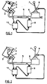
- Figures 1, 2, 3 and 4 show schematically a part of the hydraulic system of a multifunctional machine, which could be, for example, a hydraulic excavator or a shovel loader, which in addition to excavation operations could also carry out lifting work and then has to be provided with a hose breakage safety system.
- a multifunctional machine which could be, for example, a hydraulic excavator or a shovel loader, which in addition to excavation operations could also carry out lifting work and then has to be provided with a hose breakage safety system.
- a multifunctional machine could be, for example, a hydraulic excavator or a shovel loader, which in addition to excavation operations could also carry out lifting work and then has to be provided with a hose breakage safety system.
- Figures 1, 2, 3 and 4 show a cylinder 1 of a lifting arm 2 of, for example, an excavator.
- An electrical non-return valve 4 is provided near the inflow aperture 3 of the cylinder 1.
- the oil runs through a hose 5 via the non-return valve 4 to the cylinder 1.
- the oil supply and discharge is regulated by a control valve 6 by means of an operating lever 7.
- Said operating lever 7 switches a mechanical switch 8 on and off depending on the position of the lever.
- An electrical pressure sensor 9 is placed near the inflow aperture of the hose 5 on the control valve 6.
- a control unit 10 provided with the desired electronics, ensures the correct operation of the hose breakage safety system.
- Figure 1 shows how the system works when the arm or boom is lifted.
- the switch 8 is not activated, so the hose breakage safety system monitor is not in operation.
- the machine is, however, automatically safeguarded against breakage of the hose, due to the fact that when pressure no longer comes through at the ingoing port or inflow aperture of the cylinder 1 the non-return valve 4 automatically falls shut and no further oil can flow out, and it can thus no longer flow back.
- the lifting arm, boom or mast 2 will thus automatically stop.
- Figure 2 shows the neutral position. In this position also the hose breakage safety system is not in operation. The non-return valve 4 is closed in this position and nothing can happen if the hose breaks.
- Figure 3 shows what happens if the lifting arm 2 is being lowered.
- the non-return valve 4 must be kept open. However, in order to be able to open the non-return valve and keep it open, a number of conditions must be met.
- the operating lever 7 must be placed in the position for lowering of the mast 2.
- the switch 8 will be depressed and the control unit 10 will consequently receive current and immediately afterwards emit a brief measured pulse, as a result of which the non-return valve 4 is opened during the brief pulse period; the hose will thereby come to pressure and at the other side of the hose 5 the pressure sensor 9 will observe a pressure wave.
- This pressure sensor 9 will convert the measured pressure into an electrical signal which is sent to the control unit 10.
- the latter compares the received electrical pulse with the outgoing pulse and, if it corresponds thereto within a predetermined limit, this will indicate that the hose is in good condition.
- the control unit 10 will now open the valve 4, and said valve 4 remains open so long as pressure is measured by the pressure sensor 9.
- FIG. 4 shows the situation in which the hose 5 is broken. No pressure will now be measured by the pressure sensor 9, and so no electrical pulse will be emitted to the control unit 10. The valve 4 will now remain closed, and it will not be possible to lower the lifting arm.
- Figure 5 shows a number of experiments which were carried out with a machine always provided with a number of generally known hose breakage safety systems. It was found that as soon as breakage was simulated without the operating person being aware of it the lifting arm always made a considerable fall. The machine provided with the present hose breakage safety system was, however, found to give the best result. The lifting arm did actually make a slight fall from the position where the breakage occurred (from position A, the initial position for all experiments, to position B), but this was only a small part of the full potential fall length.
- An additional advantage of the present hose breakage safety system is that during normal use, i.e. when no breakage has occurred in the hose, the lifting arm or lever 2 can be moved at virtually the maximum possible speed from the top position to the bottom.
- Machines which are equipped with a hose breakage safety system according to the invention are also provided with a switch by means of which the safety system can be switched off. This is important in particular for, for example, being able to use an earthmoving machine as an excavator, in which case the boom does not, of course, need to make any downgoing movement.
Landscapes
- Engineering & Computer Science (AREA)
- Mining & Mineral Resources (AREA)
- Civil Engineering (AREA)
- General Engineering & Computer Science (AREA)
- Structural Engineering (AREA)
- Component Parts Of Construction Machinery (AREA)
- Examining Or Testing Airtightness (AREA)
- Rigid Pipes And Flexible Pipes (AREA)
- Fire-Extinguishing By Fire Departments, And Fire-Extinguishing Equipment And Control Thereof (AREA)
- Fluid-Pressure Circuits (AREA)
- Control And Safety Of Cranes (AREA)
- Forklifts And Lifting Vehicles (AREA)
Claims (1)
- Verfahren zur Vermeidung einer nicht voraussehbaren Bewegung, wenn ein plötzlicher Druckverlust in einer hydraulischen Anlage oder in einem Schlauch (5) oder einem Teil eines Hebezeugs oder Hebegeräts auftritt, welcher zerstörungsgefährdet ist, für welches ein elektrisches Rückschlagventil (4) in der Nähe eines Endes eines Schlauches (5) oder des zerstörungsgefährdeten Teils sowie weiter ein Druckfühler (9) in der Nähe des anderen Endes des Schlauches (5) oder des zerstörungsgefährdeten Teils angeordnet ist, wobei der Druckfühler (9) ein elektrisches Signal abgibt, das proportional zum gemessenen Druck ist und das ständig mit einem gewünschten Signal verglichen wird, wobei das Ventil (4) geschlossen ist, sobald das Signal aus dem Druckfühler (9) von dem gewünschten Signal um mehr als die vorgegebenen Grenzen abweicht, dadurch gekennzeichnet, daß, sobald ein Hebezeug in Betrieb genommen wird, ein elektrischer Impuls, der das Ventil (4) über eine spezifisch kurze Zeit öffnet, an das Elektroventil (4) gesendet wird und dadurch, daß mehr oder weniger gleichzeitig der Druckfühler (9) eine Druckmessung über einen vorbestimmten Zeitraum vornimmt, wobei die Druckmessung durch den Druckfühler (9) in einen elektrischen Impuls umgewandelt wird, dessen Größe ein Maß des gemessenen Drucks ist, wobei danach das Elektroventil (4) geöffnet wird, wenn der elektrische Impuls, aus dem Druckfühler (9) kommend, innerhalb der vorgegebenen Grenzen einem vorbestimmten elektrischen Impulsniveau entspricht und dadurch , daß nach Öffnen des Elektroventils (4) das aus dem Druckfühler (9) kommende Signal ständig mit einem gewünschten Signal verglichen wird und das Ventil geschlossen wird, sobald das Signal aus dem Druckfühler von dem gewünschten Signal um mehr als die vorgegebenen Grenzen abweicht.
Priority Applications (1)
| Application Number | Priority Date | Filing Date | Title |
|---|---|---|---|
| AT90201632T ATE97972T1 (de) | 1989-06-22 | 1990-06-20 | Sicherheitssystem zum verhindern eines schlauchbruchs. |
Applications Claiming Priority (2)
| Application Number | Priority Date | Filing Date | Title |
|---|---|---|---|
| NL8901572A NL8901572A (nl) | 1989-06-22 | 1989-06-22 | Slangbreukbeveiligingssysteem. |
| NL8901572 | 1989-06-22 |
Publications (2)
| Publication Number | Publication Date |
|---|---|
| EP0404271A1 EP0404271A1 (de) | 1990-12-27 |
| EP0404271B1 true EP0404271B1 (de) | 1993-12-01 |
Family
ID=19854879
Family Applications (1)
| Application Number | Title | Priority Date | Filing Date |
|---|---|---|---|
| EP90201632A Expired - Lifetime EP0404271B1 (de) | 1989-06-22 | 1990-06-20 | Sicherheitssystem zum Verhindern eines Schlauchbruchs |
Country Status (4)
| Country | Link |
|---|---|
| EP (1) | EP0404271B1 (de) |
| AT (1) | ATE97972T1 (de) |
| DE (1) | DE69004866T2 (de) |
| NL (1) | NL8901572A (de) |
Cited By (1)
| Publication number | Priority date | Publication date | Assignee | Title |
|---|---|---|---|---|
| EP3699438B1 (de) * | 2019-02-22 | 2024-03-13 | Robert Bosch GmbH | Rückschlagventilsystem mit elektronischer kontrolle |
Families Citing this family (3)
| Publication number | Priority date | Publication date | Assignee | Title |
|---|---|---|---|---|
| US5860233A (en) * | 1997-04-14 | 1999-01-19 | Caterpillar Inc. | Valve configuration and mounting arrangement |
| ITPR20040007A1 (it) * | 2004-02-06 | 2004-05-06 | Oleostar S P A | Sistema di sicurezza in apparati idraulici di comando di caricatori frontali di macchine operatrici durante le fasi di sollevamento e di stazionamento del carico. |
| JP5850021B2 (ja) * | 2013-10-30 | 2016-02-03 | コベルコ建機株式会社 | 建設機械の配索構造 |
Family Cites Families (3)
| Publication number | Priority date | Publication date | Assignee | Title |
|---|---|---|---|---|
| GB1502234A (en) * | 1976-09-01 | 1978-02-22 | Volvo Bm | System for preventing a load from falling in the event of a conduit break to a hydraulic cylinder or other hydraulic motor lifting the load |
| FR2397578A1 (fr) * | 1977-07-13 | 1979-02-09 | Baudet Alain | Dispositif de securite pour supprimer les risques d'accident sur les machines hydrauliques |
| FR2497851A1 (fr) * | 1981-01-12 | 1982-07-16 | Mascha Roger | Dispositifs de securites pour pelles mecaniques |
-
1989
- 1989-06-22 NL NL8901572A patent/NL8901572A/nl not_active Application Discontinuation
-
1990
- 1990-06-20 DE DE90201632T patent/DE69004866T2/de not_active Expired - Lifetime
- 1990-06-20 AT AT90201632T patent/ATE97972T1/de active
- 1990-06-20 EP EP90201632A patent/EP0404271B1/de not_active Expired - Lifetime
Cited By (1)
| Publication number | Priority date | Publication date | Assignee | Title |
|---|---|---|---|---|
| EP3699438B1 (de) * | 2019-02-22 | 2024-03-13 | Robert Bosch GmbH | Rückschlagventilsystem mit elektronischer kontrolle |
Also Published As
| Publication number | Publication date |
|---|---|
| ATE97972T1 (de) | 1993-12-15 |
| DE69004866D1 (de) | 1994-01-13 |
| NL8901572A (nl) | 1991-01-16 |
| DE69004866T2 (de) | 1994-04-21 |
| EP0404271A1 (de) | 1990-12-27 |
Similar Documents
| Publication | Publication Date | Title |
|---|---|---|
| EP0739437B1 (de) | Vorrichtung und verfahren zur steuerung eines werkzeuges einer baumaschine | |
| KR100801383B1 (ko) | 작업용 차량 | |
| US4427121A (en) | Hydraulic valve control for aerial book devices | |
| EP0384737A1 (de) | Hydraulischer Kreislauf für eine Erdbewegungsmaschine | |
| EP0404271A1 (de) | Sicherheitssystem zum Verhindern eines Schlauchbruchs | |
| CN114934559B (zh) | 快换装置脱开控制系统、方法和工程机械 | |
| EP0148109B1 (de) | Pfahlrammvorrichtung und Verfahren zur Betätigung einer derartigen Vorrichtung | |
| EP0708053A1 (de) | Sicherheitsanlage für hydraulische Auslegerkräne, insbesondere für Motorfahrzeugkräne | |
| KR100795612B1 (ko) | 유압중장비의 붐하강제어장치 | |
| KR100607340B1 (ko) | 이동식 크레인의 아우트리거 자동 수평 시스템 | |
| JP3877871B2 (ja) | クレーン仕様の油圧ショベルに於ける吊り荷重演算方法 | |
| JP2006022563A (ja) | 作業機械とアタッチメント判別方法 | |
| DK1490288T3 (en) | Load control system, preferably for boom cranes | |
| KR200389671Y1 (ko) | 휠로더의 붐하강 충격저감장치 | |
| CN207965609U (zh) | 一种矿山提升系统中罐道绳自动张紧智能控制系统 | |
| EP1641702B1 (de) | Hebemechanismus | |
| JPH11322261A (ja) | クレーン仕様の油圧ショベルに於ける吊り荷重演算方法 | |
| JP4319529B2 (ja) | クレーン機能付き油圧ショベル | |
| SU1605046A1 (ru) | Система защиты гидропривода | |
| CN112302068A (zh) | 高度限定装置、方法及挖掘机 | |
| KR20210001268A (ko) | 건설 기계 | |
| KR920004544Y1 (ko) | 굴삭기의 크레인 작업 안전장치 | |
| KR19990039719U (ko) | 굴삭기의 흙다지기 작업 제어장치 | |
| JP2005146567A (ja) | クレーン仕様の油圧ショベル。 | |
| KR20020011554A (ko) | 공작기계의 엘리베이터 캐빈 비상정지용 안전장치 |
Legal Events
| Date | Code | Title | Description |
|---|---|---|---|
| PUAI | Public reference made under article 153(3) epc to a published international application that has entered the european phase |
Free format text: ORIGINAL CODE: 0009012 |
|
| AK | Designated contracting states |
Kind code of ref document: A1 Designated state(s): AT BE CH DE DK ES FR GB GR IT LI LU NL SE |
|
| 17P | Request for examination filed |
Effective date: 19901205 |
|
| 17Q | First examination report despatched |
Effective date: 19920402 |
|
| GRAA | (expected) grant |
Free format text: ORIGINAL CODE: 0009210 |
|
| AK | Designated contracting states |
Kind code of ref document: B1 Designated state(s): AT BE CH DE DK ES FR GB GR IT LI LU NL SE |
|
| PG25 | Lapsed in a contracting state [announced via postgrant information from national office to epo] |
Ref country code: IT Free format text: LAPSE BECAUSE OF FAILURE TO SUBMIT A TRANSLATION OF THE DESCRIPTION OR TO PAY THE FEE WITHIN THE PRESCRIBED TIME-LIMIT;WARNING: LAPSES OF ITALIAN PATENTS WITH EFFECTIVE DATE BEFORE 2007 MAY HAVE OCCURRED AT ANY TIME BEFORE 2007. THE CORRECT EFFECTIVE DATE MAY BE DIFFERENT FROM THE ONE RECORDED. Effective date: 19931201 Ref country code: SE Effective date: 19931201 Ref country code: GR Free format text: LAPSE BECAUSE OF FAILURE TO SUBMIT A TRANSLATION OF THE DESCRIPTION OR TO PAY THE FEE WITHIN THE PRESCRIBED TIME-LIMIT Effective date: 19931201 Ref country code: CH Effective date: 19931201 Ref country code: FR Effective date: 19931201 Ref country code: ES Free format text: THE PATENT HAS BEEN ANNULLED BY A DECISION OF A NATIONAL AUTHORITY Effective date: 19931201 Ref country code: DK Effective date: 19931201 Ref country code: AT Effective date: 19931201 Ref country code: LI Effective date: 19931201 |
|
| REF | Corresponds to: |
Ref document number: 97972 Country of ref document: AT Date of ref document: 19931215 Kind code of ref document: T |
|
| REF | Corresponds to: |
Ref document number: 69004866 Country of ref document: DE Date of ref document: 19940113 |
|
| REG | Reference to a national code |
Ref country code: CH Ref legal event code: PL |
|
| EN | Fr: translation not filed | ||
| PG25 | Lapsed in a contracting state [announced via postgrant information from national office to epo] |
Ref country code: LU Free format text: LAPSE BECAUSE OF NON-PAYMENT OF DUE FEES Effective date: 19940630 |
|
| PLBE | No opposition filed within time limit |
Free format text: ORIGINAL CODE: 0009261 |
|
| STAA | Information on the status of an ep patent application or granted ep patent |
Free format text: STATUS: NO OPPOSITION FILED WITHIN TIME LIMIT |
|
| 26N | No opposition filed | ||
| REG | Reference to a national code |
Ref country code: GB Ref legal event code: IF02 |
|
| PGFP | Annual fee paid to national office [announced via postgrant information from national office to epo] |
Ref country code: BE Payment date: 20030611 Year of fee payment: 14 |
|
| PG25 | Lapsed in a contracting state [announced via postgrant information from national office to epo] |
Ref country code: BE Free format text: LAPSE BECAUSE OF NON-PAYMENT OF DUE FEES Effective date: 20040630 |
|
| BERE | Be: lapsed |
Owner name: *NIJHUIS JOHANNES Effective date: 20040630 |
|
| PGFP | Annual fee paid to national office [announced via postgrant information from national office to epo] |
Ref country code: NL Payment date: 20090629 Year of fee payment: 20 |
|
| PGFP | Annual fee paid to national office [announced via postgrant information from national office to epo] |
Ref country code: DE Payment date: 20090701 Year of fee payment: 20 Ref country code: GB Payment date: 20090521 Year of fee payment: 20 |
|
| REG | Reference to a national code |
Ref country code: NL Ref legal event code: V4 Effective date: 20100620 |
|
| REG | Reference to a national code |
Ref country code: GB Ref legal event code: PE20 Expiry date: 20100619 |
|
| PG25 | Lapsed in a contracting state [announced via postgrant information from national office to epo] |
Ref country code: NL Free format text: LAPSE BECAUSE OF EXPIRATION OF PROTECTION Effective date: 20100620 |
|
| PG25 | Lapsed in a contracting state [announced via postgrant information from national office to epo] |
Ref country code: GB Free format text: LAPSE BECAUSE OF EXPIRATION OF PROTECTION Effective date: 20100619 |
|
| PG25 | Lapsed in a contracting state [announced via postgrant information from national office to epo] |
Ref country code: DE Free format text: LAPSE BECAUSE OF EXPIRATION OF PROTECTION Effective date: 20100620 |