EP0404281A1 - Silageentnahmevorrichtung aus einem Silo - Google Patents
Silageentnahmevorrichtung aus einem Silo Download PDFInfo
- Publication number
- EP0404281A1 EP0404281A1 EP90202292A EP90202292A EP0404281A1 EP 0404281 A1 EP0404281 A1 EP 0404281A1 EP 90202292 A EP90202292 A EP 90202292A EP 90202292 A EP90202292 A EP 90202292A EP 0404281 A1 EP0404281 A1 EP 0404281A1
- Authority
- EP
- European Patent Office
- Prior art keywords
- cylinder
- piston
- cutter plate
- support frame
- silage
- Prior art date
- Legal status (The legal status is an assumption and is not a legal conclusion. Google has not performed a legal analysis and makes no representation as to the accuracy of the status listed.)
- Withdrawn
Links
Images


Classifications
-
- A—HUMAN NECESSITIES
- A01—AGRICULTURE; FORESTRY; ANIMAL HUSBANDRY; HUNTING; TRAPPING; FISHING
- A01F—PROCESSING OF HARVESTED PRODUCE; HAY OR STRAW PRESSES; DEVICES FOR STORING AGRICULTURAL OR HORTICULTURAL PRODUCE
- A01F25/00—Storing agricultural or horticultural produce; Hanging-up harvested fruit
- A01F25/16—Arrangements in forage silos
- A01F25/20—Unloading arrangements
- A01F25/2027—Unloading arrangements for trench silos
- A01F25/2036—Cutting or handling arrangements for silage blocks
-
- B—PERFORMING OPERATIONS; TRANSPORTING
- B23—MACHINE TOOLS; METAL-WORKING NOT OTHERWISE PROVIDED FOR
- B23D—PLANING; SLOTTING; SHEARING; BROACHING; SAWING; FILING; SCRAPING; LIKE OPERATIONS FOR WORKING METAL BY REMOVING MATERIAL, NOT OTHERWISE PROVIDED FOR
- B23D49/00—Machines or devices for sawing with straight reciprocating saw blades, e.g. hacksaws
- B23D49/003—Machines or devices for sawing with straight reciprocating saw blades, e.g. hacksaws having a plurality of saw blades or saw blades having plural cutting zones
- B23D49/006—Machines or devices for sawing with straight reciprocating saw blades, e.g. hacksaws having a plurality of saw blades or saw blades having plural cutting zones with contiguous, oppositely reciprocating saw blades
-
- B—PERFORMING OPERATIONS; TRANSPORTING
- B26—HAND CUTTING TOOLS; CUTTING; SEVERING
- B26D—CUTTING; DETAILS COMMON TO MACHINES FOR PERFORATING, PUNCHING, CUTTING-OUT, STAMPING-OUT OR SEVERING
- B26D1/00—Cutting through work characterised by the nature or movement of the cutting member or particular materials not otherwise provided for; Apparatus or machines therefor; Cutting members therefor
- B26D1/01—Cutting through work characterised by the nature or movement of the cutting member or particular materials not otherwise provided for; Apparatus or machines therefor; Cutting members therefor involving a cutting member which does not travel with the work
- B26D1/04—Cutting through work characterised by the nature or movement of the cutting member or particular materials not otherwise provided for; Apparatus or machines therefor; Cutting members therefor involving a cutting member which does not travel with the work having a linearly-movable cutting member
- B26D1/06—Cutting through work characterised by the nature or movement of the cutting member or particular materials not otherwise provided for; Apparatus or machines therefor; Cutting members therefor involving a cutting member which does not travel with the work having a linearly-movable cutting member wherein the cutting member reciprocates
- B26D1/10—Cutting through work characterised by the nature or movement of the cutting member or particular materials not otherwise provided for; Apparatus or machines therefor; Cutting members therefor involving a cutting member which does not travel with the work having a linearly-movable cutting member wherein the cutting member reciprocates in, or substantially in, a direction parallel to the cutting edge
-
- B—PERFORMING OPERATIONS; TRANSPORTING
- B26—HAND CUTTING TOOLS; CUTTING; SEVERING
- B26D—CUTTING; DETAILS COMMON TO MACHINES FOR PERFORATING, PUNCHING, CUTTING-OUT, STAMPING-OUT OR SEVERING
- B26D1/00—Cutting through work characterised by the nature or movement of the cutting member or particular materials not otherwise provided for; Apparatus or machines therefor; Cutting members therefor
- B26D1/01—Cutting through work characterised by the nature or movement of the cutting member or particular materials not otherwise provided for; Apparatus or machines therefor; Cutting members therefor involving a cutting member which does not travel with the work
- B26D1/04—Cutting through work characterised by the nature or movement of the cutting member or particular materials not otherwise provided for; Apparatus or machines therefor; Cutting members therefor involving a cutting member which does not travel with the work having a linearly-movable cutting member
- B26D1/06—Cutting through work characterised by the nature or movement of the cutting member or particular materials not otherwise provided for; Apparatus or machines therefor; Cutting members therefor involving a cutting member which does not travel with the work having a linearly-movable cutting member wherein the cutting member reciprocates
- B26D1/10—Cutting through work characterised by the nature or movement of the cutting member or particular materials not otherwise provided for; Apparatus or machines therefor; Cutting members therefor involving a cutting member which does not travel with the work having a linearly-movable cutting member wherein the cutting member reciprocates in, or substantially in, a direction parallel to the cutting edge
- B26D1/11—Cutting through work characterised by the nature or movement of the cutting member or particular materials not otherwise provided for; Apparatus or machines therefor; Cutting members therefor involving a cutting member which does not travel with the work having a linearly-movable cutting member wherein the cutting member reciprocates in, or substantially in, a direction parallel to the cutting edge with a plurality of cutting members
Definitions
- the invention relates to a device for removing silage from a silage supply in accordance with the preamble of claim 1.
- Such a silage cutter is known for instance from EP-A 0 264 157.
- This known silage cutter has a U-shaped support frame and comprises one common driving for the three movable cutter plates.
- special steps are necessary to transmit the forces of movement from the one cutter plate to the other, for example rocker pieces, corner chains or special cables.
- the object of the invention is to provide a silage cutter of the above-mentioned type, wherein the use of such special means as corner chains, rocker pieces or the like, is avoided.
- the silage cutter according to the invention is characterized by the feature of the characterizing part of claim 1.
- the silage cutter preferably has the feature that a drive unit comprises at least one pair of single-action cylinder-piston assemblies acting in mutually opposing directions or at least one double-action cylinder-piston assembly.
- the cylinder-piston assemblies are energised in accordance with a continuous periodic function.
- the cutter plates perform for example a gradual reciprocating movement, without abrupt changes of direction.
- the cutter plates can also be accelerated away from their one end position and then slowed down again until they come to a standstill in the other end position, after which again follows acceleration in the opposing direction.
- a very simple driving is that of a variant displaying the feature that the corresponding cylinder-piston assemblies of different pairs are connected in parallel.
- At least the cutter plate associated with one leg of the support frame can be driven by means of at least one cylinder-piston assembly mounted in said leg, which assembly is coupled thereto by means of a coupling member which is connected in fixed manner to the piston of the or each cylinder-piston assembly.
- each cylinder-piston assembly is provided with a cylinder housing with central opening, wherein the piston in the form of a piston rod is accessible through this central opening and is borne on either side of the opening in the cylinder housing and wherein the coupling member is joined to the piston rod in this central opening.
- the device displays the further feature that the teeth of each pair of co-acting cutter plates have the same pitch distance and that the drivings take a form such that the movement of each movable cutter plate takes place in such a way that at the ends of each stroke the teeth of the movable cutter plate and those of the stationary cutter plate are positioned symmetrically relative to the point halfway between the points of the teeth, that preferably they coincide at least substantially such that the co-acting cutting edges perform successive scissor-like movements.
- Such a scissor-like movement can be performed particularly effectively if at the end of each stroke the teeth are held at rest for a short time relative to the duration of the stroke, such by means of a buffering suitable for this purpose.
- a buffering suitable for this purpose As a result, when the support frame is set in downward motion, the space between the teeth can always be very well filled with the material for cutting and a real scissor-like movement is carried out very effectively, resulting in the useful effect of the cutting becoming significantly greater.
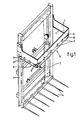
- the device shown in fig. 1 for cutting silage possesses a substantially vertical extending guiding frame 1 and an at least virtually horizontal U-shaped support frame 2 that can move up and down along this guiding frame 1.
- a cylinder-piston assembly 3 employed in a manner not further indicated for this up and downward movement of the support frame 2 relative to guiding frame 1 is a cylinder-piston assembly 3.
- the guiding frame 1 On its lower outer end the guiding frame 1 has bearing teeth 4 for carrying a cut-out block of silage.
- the device shown in fig. 1 can be mounted in its entirety on the front or rear of a tractor.
- the support fram 2 is provided on each of its three sides with a downward directed cutting member 5, 6, 7 that is movable reciprocally in horizontal direction for a cutting action.
- the reciprocal movement of these cutting members 5, 6, 7 is brought about by cylinder-piston assemblies 8 which are shown only schematically in fig. 1.
- each cutting member comprises two closely adjoining cutter plates 10 and 11, the cutter plate 10 being in fixed connection with the support frame 2.
- the reciprocally movable cutter plates are locked with respect to the support frame 2 by retaining lips 9 which are also only shown schematically in fig. 1.
- the cutter plates 10 and 11 have series of cutting teeth.
- cutter plates 11 Arranged in cutter plates 11 are guide slots 14 which co-operate with attachment members 12 of the fixed cutter plates, in the form for example of socket head screws, arranged in the support frame 2.
- support portions 15 Fixed to the support frame 2 for the absorption of the vertical forces acting on the reciprocally movable cutter plate 11 are support portions 15 of bronze or the like which co-act with the upper edge of the reciprocally movable cutter plate 11 facing away from the series of cutting teeth. It is additionally noted that the retaining lips 9 may likewise be made of bronze or the like. Both the retaining lips 9 and the support portions 15 are connected to the support frame 2 by fastening members 13.
- the cylinder-piston assemblies 8 already illustrated schematically in fig. 1 are attached to support fram 2 by means of fastening members 16.
- the movable cutter plates 11 have cut-away portions 17 which accommodate the associated cylinder-piston assemblies.
- the piston rods 18 of the cylinder-piston assemblies 8 grip with their outer ends onto one of the side edges of each cut-away portion 17.
- the outer end of this piston rod 18 presses against the said side edge of the cut-away portion 17 and the movable cutter plate is displaced with respect to the support frame 2.
- each cylinder-piston assembly can be of the double-action type that can displace a movable cutter plate 11 in one direction as well as the opposing direction.
- each movable cutter plate 11 is furnished with a pair of single cylinder-piston assemblies 8 acting in opposing directions.
- Each cylinder-piston assembly 8 can hereby exert a force in only one direction.
- a protective cover that may optionally be arranged around each cylinder-piston assembly 8.
- the series of cutting teeth (as shown in fig. 2) have a tooth pitch equal to or a little smaller than the stroke of both cutter plates 10 and 11 relative to one another (as defined for instance by the length of the groove 14 or, as in figure 10, by the interval between the piston 117 and the cover 124).
- tooth points of the series of cutting teeth of both cutter plates 10 and 11 are located at least virtually in the same horizontal plane.
- Shown in fig. 5 is a hydraulic working diagram for another way of energising the cylinder-piston assemblies.
- This single-action cylinder-piston assemblies of the three cutting members 5-7 are designated with the reference numerals 21-26.
- Each cylinder-piston assembly 21-26 is connected via a line to the outlet of an associated pump cylinder 27-32.
- the pump cylinders 27-32 are positioned about an eccentric 33 in the form of a circular disc with an eccentric axis of rotation.
- the eccentric 33 is driven by a hydromotor 34.
- the pump cylinders 27-32 When the eccentric 33 is driven by the hydromotor 34 the pump cylinders 27-32 will be energised via a continuous periodic function, in this case a sine function, whereby the coupling between these pump cylinders and the associated cylinder-piston assemblies 21-26 leads to a similarly continuous periodic energising of these cylinder-piston assemblies.
- the pump cylinders 27-32 are positioned around the eccentric 33 such that the pump cylinders connected to the cylinder-piston assemblies belonging to one pair are each positioned on opposite facing sides of the eccentric 33. In this way the pump cylinders 27 and 28, 29 and 30, and 31 and 32 are always positioned opposite each other.
- a further pump cylinder 35 which provides the energising of the cylinder-piston assembly 3 (see fig. 1) for the up and downward movement of the support frame 2.
- the pump cylinders 27-32 are distributed regularly about the eccentric 33 so that a regular loading is applied thereto.
- the capacity of the hydromotor 34 can be minimal as a result.
- a rapid-action feed 35 for the cylinder-piston assembly 3 safety valves 36, filler valves 37, a biased filler valve 38 in addition to a control valve 39 that can for instance be operated from the tractor.
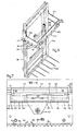
- Shown in fig. 6 is a device for cutting silage, which is provided with a substantially vertical standing guiding frame 101 and an at least virtually horizontal U-shaped support frame 102.
- the support frame 102 is movable with its legs up and down along the guiding frame 101 by means of a cylinder-piston assembly 104. This driving of the support frame is per se known and is therefore not described further.
- the guiding frame 101 comprises bearing teeth 105 for carrying a cut-out block of silage.
- the device described can be coupled in the usual manner to a tractor.
- the U-shaped support frame is provided on each of the legs 103 and on the body 106 with a cutting member 107 which consists in the embodiment shown of a stationary blade 108 and a blade 109 that is reciprocally movable relative to the support frame 102.
- the moving blade 109 is held in position on the support frame 102 using retaining lips 110.
- reference is made to the older Dutch priority application 8801220.
- the driving of the movable cutting blade 109 of both legs 103 is provided by a double-action hydraulic cylinder-piston assembly 111, of which only one is shown in fig. 9.
- the driving of the movable cutting blade 109 of the body 106 is taken care of by two double-action cylinder-piston assemblies 112, one of which is shown in detail in the figures 7 and 8.
- Each cylinder-piston assembly 112 is provided with a cylinder housing 113 that protrudes into a recess 114 in the body 106 of the support frame 102. Cylinder housing 113 is fastened to the body 106 using two bolts 115.
- the cylinder housing 113 has a central opening 116, wherein the piston in the form of a piston rod 117 runs through this central opening and is borne on either side thereof in elongate guide bushings 118 that are fitted in cylinder housing 113.
- Guide bushings 118 preferably consist of bronze.
- a casing 110 which encloses piston rod 117 in close fitting manner.
- Fixed to the casing 119 on the underside is a coupling plate 121.
- the coupling plate 121 is connected at its lower end to the cutting blade 109 by means of a bolt 122.
- each chamber 123 can be connected, via its own oil channel 125 and oil line 126 connected thereto, to a hydraulic control system, such that chambers 123 are joined alternately to the pressure and return pipes of a hydraulic power source.
- the teeth 151 display symmetrical points, the cutting edges 152 of which have ends which form angles 153 of more than 30°, and in this embodiment even of almost 90°, with the connecting line 154 between the points 151.
- the apex angle of the symmetrical teeth is thus smaller here than 120o, and even almost 0°.
- This form ensures the very effective scissor-like action described in the foregoing.
- the driving takes place for this purpose in such a way that the movable cutter plates move reciprocally such that at the ends of each stroke the teeth of the movable cutter plate and the teeth of the fixed cutter plate are located symmetrically relative to the point halfway between the points of the teeth.
- the teeth coincide at least substantially at the ends of each stroke.
- the latter method of driving in particular ensures that the co-acting cutting edges perform very effective successive scissor-like movements.
- each cylinder-piston assembly 112 lies on the inside of the support frame 102 relative to the movable cutting blade 109.
- a result a comparatively small force is needed to move the support frame 102 downward through the silage, since the inward protruding cylinder housing 113, which is also protected by a guiding plate 127, can press away the cut-out silage relatively easily.
- the movable cutting blade 109 is connected in the manner described to the piston rod 117 by means of casing 119 and coupling plate 121, the moments generated during operation by the cutting force are absorbed in the piston rod 117 and the guide bushings 118 and virtually no moments are created in the cutting blade 109.
- the moment caused by the distance between the centre line of the cutting blade 109 and the centre line of the piston rod 117 in the direction transversely of cutting blade 109 is also absorbed in piston rod 117 and guide bushings 118. This ensures a long useful life of the cutting blade 109.
- the moments that occur cause hardly any problem for the cylinder-piston assembly 112, since its components can be designed to absorb any moments that occur and good lubrication of the piston rod 117 in the guide bushings 118 is simply carried out.
- the cutting blade 109 of the body 106 is driven with the cylinder-piston assemblies 112
- the cutting blades 109 of the legs 103 can if required also be driven by such cylinder-piston assemblies.
- a cylinder-piston assembly 112 is arranged on either side of cutting blade 109 of body 106, it is also possible to dispose one or more cylinder-piston assemblies 112 above on another at least roughly in the middle of the cutting blade 109.
- the cylinder housings 113 thereof can be combined into a common housing.
- the piston rod 117 for generating the reguired forces may have an oval section.
Landscapes
- Life Sciences & Earth Sciences (AREA)
- Engineering & Computer Science (AREA)
- Mechanical Engineering (AREA)
- Environmental Sciences (AREA)
- Forests & Forestry (AREA)
- Harvester Elements (AREA)
- Shearing Machines (AREA)
- Crushing And Pulverization Processes (AREA)
- Threshing Machine Elements (AREA)
Applications Claiming Priority (4)
| Application Number | Priority Date | Filing Date | Title |
|---|---|---|---|
| NL8801220 | 1988-05-09 | ||
| NL8801220A NL8801220A (nl) | 1988-05-09 | 1988-05-09 | Inrichting voor het snijden van kuilvoer. |
| NL8801537A NL8801537A (nl) | 1988-06-16 | 1988-06-16 | Inrichting voor het snijden van kuilvoer. |
| NL8801537 | 1988-06-16 |
Related Parent Applications (1)
| Application Number | Title | Priority Date | Filing Date |
|---|---|---|---|
| EP88202816.0 Division | 1988-12-08 |
Publications (1)
| Publication Number | Publication Date |
|---|---|
| EP0404281A1 true EP0404281A1 (de) | 1990-12-27 |
Family
ID=26646384
Family Applications (5)
| Application Number | Title | Priority Date | Filing Date |
|---|---|---|---|
| EP88202815A Withdrawn EP0341350A1 (de) | 1988-05-09 | 1988-12-08 | Silageblockschneider mit zusammenarbeitenden Zahnreihen mit unterschiedlichen Steigungen |
| EP90202292A Withdrawn EP0404281A1 (de) | 1988-05-09 | 1988-12-08 | Silageentnahmevorrichtung aus einem Silo |
| EP88202816A Expired - Lifetime EP0341351B1 (de) | 1988-05-09 | 1988-12-08 | Silagegutschneider mit getrennten Antriebsmitteln |
| EP90202293A Expired - Lifetime EP0411724B2 (de) | 1988-05-09 | 1988-12-08 | Silageentnahmevorrichtung aus einem Silo |
| EP88202817A Withdrawn EP0341352A1 (de) | 1988-05-09 | 1988-12-08 | Silageblockschneider mit Schneidplatten mit spitzen Zähnen |
Family Applications Before (1)
| Application Number | Title | Priority Date | Filing Date |
|---|---|---|---|
| EP88202815A Withdrawn EP0341350A1 (de) | 1988-05-09 | 1988-12-08 | Silageblockschneider mit zusammenarbeitenden Zahnreihen mit unterschiedlichen Steigungen |
Family Applications After (3)
| Application Number | Title | Priority Date | Filing Date |
|---|---|---|---|
| EP88202816A Expired - Lifetime EP0341351B1 (de) | 1988-05-09 | 1988-12-08 | Silagegutschneider mit getrennten Antriebsmitteln |
| EP90202293A Expired - Lifetime EP0411724B2 (de) | 1988-05-09 | 1988-12-08 | Silageentnahmevorrichtung aus einem Silo |
| EP88202817A Withdrawn EP0341352A1 (de) | 1988-05-09 | 1988-12-08 | Silageblockschneider mit Schneidplatten mit spitzen Zähnen |
Country Status (2)
| Country | Link |
|---|---|
| EP (5) | EP0341350A1 (de) |
| DE (2) | DE3879474T2 (de) |
Families Citing this family (4)
| Publication number | Priority date | Publication date | Assignee | Title |
|---|---|---|---|---|
| DE4121328C2 (de) * | 1991-02-01 | 1995-03-16 | Hans Von Der Heide | Transport- und Austragvorrichtung für einen Futtermittelblock |
| DE102014115308A1 (de) * | 2014-10-21 | 2016-04-21 | B. Strautmann & Söhne GmbH u. Co. KG | Gerät zur Futterentnahme aus Flachsilos |
| DE202015106267U1 (de) | 2015-11-18 | 2015-11-30 | Fliegl Agro-Center GmbH | Schneidvorrichtung zum Abtrennen von Silage |
| CN112753391A (zh) * | 2021-01-04 | 2021-05-07 | 刘怀丹 | 一种青贮料切割搬运装置 |
Citations (5)
| Publication number | Priority date | Publication date | Assignee | Title |
|---|---|---|---|---|
| CA928387A (en) * | 1969-12-19 | 1973-06-12 | Allmanna Svenska Elektriska Aktiebolaget | Arrangement for supplying energy to auxiliary device at high potential |
| DE3023986A1 (de) * | 1980-06-26 | 1982-01-14 | Heinrich 3013 Barsinghausen Bleinroth | Geraet zur entnahme von silage |
| FR2591421A1 (fr) | 1985-12-18 | 1987-06-19 | Audureau Sa | Couteau, notamment pour desileuse, et desi- leuse le comportant |
| EP0264157A1 (de) | 1986-10-16 | 1988-04-20 | C. van der Lely N.V. | Gerät zum Schneiden von Futter wie z.B. Silage |
| DE3643353A1 (de) * | 1986-12-18 | 1988-06-23 | Strautmann & Soehne | Flachsilo-entnahmegeraet |
Family Cites Families (4)
| Publication number | Priority date | Publication date | Assignee | Title |
|---|---|---|---|---|
| CA928607A (en) * | 1972-07-27 | 1973-06-19 | R. Kobelt Jack | Remote rotary control |
| ATE17300T1 (de) * | 1982-09-03 | 1986-01-15 | Trioliet Mullos | Silagegutschneider, sowie landwirtschaftliches geraet das einen solchen silagegutschneider aufweist. |
| DE3344406A1 (de) * | 1983-12-08 | 1984-04-12 | B. Strautmann & Söhne GmbH u. Co, 4518 Bad Laer | Schneidbuegel fuer siloentnahmegeraet |
| NL8801220A (nl) | 1988-05-09 | 1989-12-01 | Liet Cornelis Hendricus | Inrichting voor het snijden van kuilvoer. |
-
1988
- 1988-12-08 EP EP88202815A patent/EP0341350A1/de not_active Withdrawn
- 1988-12-08 DE DE88202816T patent/DE3879474T2/de not_active Expired - Fee Related
- 1988-12-08 EP EP90202292A patent/EP0404281A1/de not_active Withdrawn
- 1988-12-08 EP EP88202816A patent/EP0341351B1/de not_active Expired - Lifetime
- 1988-12-08 EP EP90202293A patent/EP0411724B2/de not_active Expired - Lifetime
- 1988-12-08 EP EP88202817A patent/EP0341352A1/de not_active Withdrawn
- 1988-12-08 DE DE3855608T patent/DE3855608T3/de not_active Expired - Fee Related
Patent Citations (5)
| Publication number | Priority date | Publication date | Assignee | Title |
|---|---|---|---|---|
| CA928387A (en) * | 1969-12-19 | 1973-06-12 | Allmanna Svenska Elektriska Aktiebolaget | Arrangement for supplying energy to auxiliary device at high potential |
| DE3023986A1 (de) * | 1980-06-26 | 1982-01-14 | Heinrich 3013 Barsinghausen Bleinroth | Geraet zur entnahme von silage |
| FR2591421A1 (fr) | 1985-12-18 | 1987-06-19 | Audureau Sa | Couteau, notamment pour desileuse, et desi- leuse le comportant |
| EP0264157A1 (de) | 1986-10-16 | 1988-04-20 | C. van der Lely N.V. | Gerät zum Schneiden von Futter wie z.B. Silage |
| DE3643353A1 (de) * | 1986-12-18 | 1988-06-23 | Strautmann & Soehne | Flachsilo-entnahmegeraet |
Also Published As
| Publication number | Publication date |
|---|---|
| DE3855608D1 (de) | 1996-11-14 |
| EP0341352A1 (de) | 1989-11-15 |
| EP0411724B1 (de) | 1996-10-09 |
| EP0341351A1 (de) | 1989-11-15 |
| EP0341350A1 (de) | 1989-11-15 |
| EP0411724A2 (de) | 1991-02-06 |
| EP0341351B1 (de) | 1993-03-17 |
| DE3855608T3 (de) | 2000-12-28 |
| EP0411724B2 (de) | 2000-06-07 |
| DE3879474D1 (de) | 1993-04-22 |
| DE3879474T2 (de) | 1993-10-21 |
| DE3855608T2 (de) | 1997-02-13 |
| EP0411724A3 (de) | 1991-04-24 |
Similar Documents
| Publication | Publication Date | Title |
|---|---|---|
| US4996743A (en) | Mold plate drive linkage | |
| CA1130177A (en) | Device for cutting out and transporting a silage block | |
| CA2085771A1 (en) | Swash Plate Type Compressor with Swash Plate Hinge Coupling Mechanism | |
| EP0404281A1 (de) | Silageentnahmevorrichtung aus einem Silo | |
| US3200493A (en) | Hedge trimmer | |
| US3376799A (en) | Impact machine | |
| JPH01304822A (ja) | 飼料切断装置 | |
| US3855888A (en) | Cutting equipment for a multi-line continuous casting plant | |
| IT1255437B (it) | Macchina trapuntatrice multiaghi provvista di dispositivo tagliafili | |
| EP0019633B1 (de) | Axialkolbenpumpe | |
| US3626445A (en) | Hydraulic power tool | |
| US5976184A (en) | Artificial heart driving device | |
| RU2048055C1 (ru) | Устройство для отрезания и погрузки сенажа и силоса | |
| KR200496008Y1 (ko) | 장작 쪼개는 장치 | |
| DE2041027C3 (de) | Pumpe zum Fördern eines hydraulischen Mittels | |
| EP0491681B1 (de) | Gerät zum Schneiden von Futter, z.B. Silagegut | |
| CN2237600Y (zh) | 软管灌装封尾机 | |
| CN219660457U (zh) | 小型自走式框锯割灌设备 | |
| EP0761087B1 (de) | Hydrauliksystem für einen Silofutterschneider und Verfahren zum Antrieb einer Schneidplatte | |
| CN2283539Y (zh) | 滑枕式弧形切割弓锯床 | |
| US11903338B2 (en) | Systems and methods for reciprocating a cutter of an agricultural harvesting head | |
| SU922277A1 (ru) | Привод исполнительного органа механогидравлического горного комбайна | |
| SU1379494A1 (ru) | Аксиально-поршневой насос | |
| RU2153947C2 (ru) | Пресс гидравлический выкрутной | |
| EP0990796B1 (de) | Zusammenbau eines mechanischen oder hydraulischen Antriebs mit einer Kolbenpumpe |
Legal Events
| Date | Code | Title | Description |
|---|---|---|---|
| PUAI | Public reference made under article 153(3) epc to a published international application that has entered the european phase |
Free format text: ORIGINAL CODE: 0009012 |
|
| AC | Divisional application: reference to earlier application |
Ref document number: 341351 Country of ref document: EP |
|
| AK | Designated contracting states |
Kind code of ref document: A1 Designated state(s): BE DE FR GB NL |
|
| 17P | Request for examination filed |
Effective date: 19901109 |
|
| 17Q | First examination report despatched |
Effective date: 19911122 |
|
| STAA | Information on the status of an ep patent application or granted ep patent |
Free format text: STATUS: THE APPLICATION IS DEEMED TO BE WITHDRAWN |
|
| 18D | Application deemed to be withdrawn |
Effective date: 19930105 |