EP0404384B1 - Handbremse mit Diebstahlschutz - Google Patents
Handbremse mit Diebstahlschutz Download PDFInfo
- Publication number
- EP0404384B1 EP0404384B1 EP19900306113 EP90306113A EP0404384B1 EP 0404384 B1 EP0404384 B1 EP 0404384B1 EP 19900306113 EP19900306113 EP 19900306113 EP 90306113 A EP90306113 A EP 90306113A EP 0404384 B1 EP0404384 B1 EP 0404384B1
- Authority
- EP
- European Patent Office
- Prior art keywords
- slide
- abutment member
- recess
- push
- button
- Prior art date
- Legal status (The legal status is an assumption and is not a legal conclusion. Google has not performed a legal analysis and makes no representation as to the accuracy of the status listed.)
- Expired - Lifetime
Links
- 230000007246 mechanism Effects 0.000 claims description 22
- 230000000994 depressogenic effect Effects 0.000 claims description 10
- 230000000295 complement effect Effects 0.000 claims description 4
- 230000000881 depressing effect Effects 0.000 claims description 2
- 239000000853 adhesive Substances 0.000 description 8
- 230000001070 adhesive effect Effects 0.000 description 8
- 238000006243 chemical reaction Methods 0.000 description 4
- 238000000034 method Methods 0.000 description 3
- 230000002093 peripheral effect Effects 0.000 description 3
- 230000006835 compression Effects 0.000 description 2
- 238000007906 compression Methods 0.000 description 2
- 230000004048 modification Effects 0.000 description 2
- 238000012986 modification Methods 0.000 description 2
- 230000000717 retained effect Effects 0.000 description 2
- 230000000712 assembly Effects 0.000 description 1
- 238000000429 assembly Methods 0.000 description 1
- 239000002131 composite material Substances 0.000 description 1
- 230000000694 effects Effects 0.000 description 1
- 238000009434 installation Methods 0.000 description 1
Images

Classifications
-
- B—PERFORMING OPERATIONS; TRANSPORTING
- B60—VEHICLES IN GENERAL
- B60R—VEHICLES, VEHICLE FITTINGS, OR VEHICLE PARTS, NOT OTHERWISE PROVIDED FOR
- B60R25/00—Fittings or systems for preventing or indicating unauthorised use or theft of vehicles
- B60R25/01—Fittings or systems for preventing or indicating unauthorised use or theft of vehicles operating on vehicle systems or fittings, e.g. on doors, seats or windscreens
- B60R25/08—Fittings or systems for preventing or indicating unauthorised use or theft of vehicles operating on vehicle systems or fittings, e.g. on doors, seats or windscreens operating on brakes or brake systems
- B60R25/086—Locking of hand-actuated control actuating means
-
- Y—GENERAL TAGGING OF NEW TECHNOLOGICAL DEVELOPMENTS; GENERAL TAGGING OF CROSS-SECTIONAL TECHNOLOGIES SPANNING OVER SEVERAL SECTIONS OF THE IPC; TECHNICAL SUBJECTS COVERED BY FORMER USPC CROSS-REFERENCE ART COLLECTIONS [XRACs] AND DIGESTS
- Y10—TECHNICAL SUBJECTS COVERED BY FORMER USPC
- Y10T—TECHNICAL SUBJECTS COVERED BY FORMER US CLASSIFICATION
- Y10T29/00—Metal working
- Y10T29/49—Method of mechanical manufacture
- Y10T29/49716—Converting
-
- Y—GENERAL TAGGING OF NEW TECHNOLOGICAL DEVELOPMENTS; GENERAL TAGGING OF CROSS-SECTIONAL TECHNOLOGIES SPANNING OVER SEVERAL SECTIONS OF THE IPC; TECHNICAL SUBJECTS COVERED BY FORMER USPC CROSS-REFERENCE ART COLLECTIONS [XRACs] AND DIGESTS
- Y10—TECHNICAL SUBJECTS COVERED BY FORMER USPC
- Y10T—TECHNICAL SUBJECTS COVERED BY FORMER US CLASSIFICATION
- Y10T70/00—Locks
- Y10T70/50—Special application
- Y10T70/5611—For control and machine elements
- Y10T70/569—Lever
- Y10T70/573—Single
-
- Y—GENERAL TAGGING OF NEW TECHNOLOGICAL DEVELOPMENTS; GENERAL TAGGING OF CROSS-SECTIONAL TECHNOLOGIES SPANNING OVER SEVERAL SECTIONS OF THE IPC; TECHNICAL SUBJECTS COVERED BY FORMER USPC CROSS-REFERENCE ART COLLECTIONS [XRACs] AND DIGESTS
- Y10—TECHNICAL SUBJECTS COVERED BY FORMER USPC
- Y10T—TECHNICAL SUBJECTS COVERED BY FORMER US CLASSIFICATION
- Y10T70/00—Locks
- Y10T70/50—Special application
- Y10T70/5889—For automotive vehicles
-
- Y—GENERAL TAGGING OF NEW TECHNOLOGICAL DEVELOPMENTS; GENERAL TAGGING OF CROSS-SECTIONAL TECHNOLOGIES SPANNING OVER SEVERAL SECTIONS OF THE IPC; TECHNICAL SUBJECTS COVERED BY FORMER USPC CROSS-REFERENCE ART COLLECTIONS [XRACs] AND DIGESTS
- Y10—TECHNICAL SUBJECTS COVERED BY FORMER USPC
- Y10T—TECHNICAL SUBJECTS COVERED BY FORMER US CLASSIFICATION
- Y10T70/00—Locks
- Y10T70/70—Operating mechanism
- Y10T70/7441—Key
- Y10T70/7486—Single key
- Y10T70/7508—Tumbler type
- Y10T70/7559—Cylinder type
- Y10T70/7576—Sliding and rotary plug
Definitions
- THIS INVENTION relates to an anti-theft mechanism operable to prevent the release of a vehicle hand brake to immobilise the vehicle and prevent unauthorised use thereof.
- a motor vehicle hand-brake customarily includes a hand-brake operating lever with an associated ratchet mechanism arranged to hold the operating lever, and thus the brake, in an "applied” position once the hand brake has been operated and after manual effort has been removed from the lever, until subsequent release of the handbrake by operation of a manually operable release member, such as a push-button, serves to lift a pawl from the ratchet of the ratchet mechanism whilst the lever is returned to the "released" position.
- a motor vehicle having such a hand-brake is herein referred to as being “of the kind referred to”.
- an anti-theft handbrake arrangement for a motor vehicle of the kind referred to, wherein a manually actuable ratchet release mechanism is provided which includes a push-button exposed at the end of a generally tubular handbrake lever within which extends a brake release rod movable longitudinally downwards in the tubular handbrake lever to release the handbrake ratchet mechanism, and wherein the push-button incorporates a cylinder lock characterised in that the brake release rod carries a slide at its upper end within the tubular handbrake lever, said cylinder lock carrying an abutment member at its lower end within the tubular handbrake lever which is rotatable, with the lock, between locked and unlocked positions, said slide having an upwardly open recess for receipt of said abutment member in the locked position and the slide further having an upwardly presented face around said recess, said abutment member being of non-circular cross-section or being eccentric with respect to the axis of said
- kit of parts for adaption of an existing vehicle hand-brake lever to incorporate an anti-theft arrangement according to the first-noted aspect of the invention
- said kit comprising an assembly including a tubular body part having a lower end adapted to fit a stub of an existing tubular brake lever, a push button slidable longitudinally within said tubular body part and exposed at an upper end of said body part, the assembly further comprising a slide slidable longitudinally within said body part below said push button, a lower end of said slide being adapted to receive an end part of a brake release rod of such existing handbrake lever, left after part of the existing brake release rod has been cut off, said lock carrying an abutment member at its lower end within said body part which is rotatable, with the lock, between locked and unlocked positions, said slide having an upwardly open recess for receipt of said abutment member in the locked position and the slide further having an upwardly presented face around said recess, said a
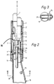
- a vehicle handbrake mechanism (not shown in detail) comprises, in conventional manner, a tubular hand-brake lever and a ratchet mechanism whereby the hand-brake, once applied, will not be released until a pawl of the ratchet mechanism is disengaged from the ratchet by depression of a brake release rod 8 running within the tubular hand-brake lever.
- the mechanism comprises a generally cylindrical slide 6 slidable axially within the hand-brake lever and urged by a compression spring 3 into a position in which the pawl of the ratchet mechanism is engaged with the ratchet.
- the spring 3 is coaxial with slide 6 and with the lever and encircles the slide 6 at the lower region of the slide.
- the mechanism further comprises a generally cylindrical push-button 1 also slidable axially within the tubular hand lever and projecting from the free end of the latter. The push-button 1 is urged axially outwardly from the hand lever by means of a further compression spring 3' encircling an intermediate part of the push button 1.
- the push-button 1 incorporates a cylinder lock connected with an abutment member 12 at the lower, inner end of the push button 1.
- the abutment member 12 is of non-circular cross-section, for example of oblong cross-section.
- the abutment member 12 In one rotational position of the abutment member 12 about the longitudinal axis of the lever, which position is adopted in the "locked" condition of the cylinder lock, the abutment member 12 is in complete register with a correspondingly shaped (for example oblong) recess 14 in an upwardly directed face 16 of the slide 6 whereby, upon axial depression of the push-button 1 in this "locked” condition, the abutment member 12 will merely move axially down into the recess 14 until the limit of axial inward movement of the push button 1 is reached, without the slide 6 being forced downward.
- the abutment member 12 is out of register with the recess 14, (for example, where the member 12 and recess 14 are both oblong in cross-section, the longer sides of the oblong cross-section of the member 12 lie at right angles to the longer sides of the oblong cross-section of the recess 14).
- the mechanism illustrated in Figure 1 is intended to be applied to a conventional handbrake of an existing vehicle by a modification procedure which entails cutting the end portion from the existing tubular handbrake lever, cutting the existing brake release rod and screw-threading the end thereof and thereafter fitting the remainder of the components shown in the drawing.
- the end of the brake release rod may be kept plain and the slide 6 may have a plain bore to receive the end of the brake release rod and the slide 6 may be bonded to the brake release rod by adhesive.
- references 10 and 8 respectively indicate the parts of the original tubular lever and push rod remaining after such a conversion procedure.
- tubular casing comprising a cylindrical outer sleeve 2 and a longitudinally split inner sleeve 7 which is a close fit within the outer sleeve and is held together by the latter.
- the outer sleeve 2 is longer than the inner sleeve 7 and the lower end of the outer sleeve 2 fits closely over the upper end of the cut-back lever 10, whilst the lower end of the longitudinally split inner sleeve 7 abuts an internal circlip 9 within the sleeve 2 which circlip 9 engages the lower end of sleeve 7 to retain the latter.
- the composite tubular casing 2, 7 encompasses the push button 1, slide 6 and springs 3 and 3', as well as location rings 4 for the springs and circlips 5 which retain the rings 4 and which circlips are engaged in circumferential grooves in the interior of the split sleeve 7.
- the lower spring 3 acts between the lower ring 4 and an annular shoulder on slide 6 and the upper spring 3' acts between the upper ring 4 and an annular abutment around the push-button 1.
- the remainder of the components shown are applied to the cut back lever 10 and rod 8 by fitting the lower end of a cylindrical outer sleeve 2 over the end of the cut-back lever and rotating the sleeve, and with it the components therein, to screw the slide 6 onto the threaded end of the modified rod 8 until an internal abutment in the sleeve 2, afforded by internal circlip 9, engages the end of the cut-back tubular lever 10.
- the sleeve 2 and the remainder of the mechanism may thereafter be conveniently held in place by an appropriate adhesive between the outer surface of the cut back tubular lever and the inner surface of the lower end of the sleeve 2, such adhesive being applied directly before fitting the casing 7, 2 to the lever 10.
- the radially outer part of the push button 1, within which the barrel of the lock is rotatable by means of the appropriate key (not shown) is, of course, retained against rotation in the sleeves 2, 7 in a manner permitting longitudinal movement along the axis of the lever.
- This may be done, for example, by providing the upper location ring with a radially outwardly projecting lug engaging in a longitudinal groove in the interior of the sleeve 7 and further providing the upper location ring 4 with a radially inwardly projecting lug engaging in a longitudinal groove in the periphery of the push button 1.
- the slide 6 is preferably retained in a like manner, by the lower location ring 4, against rotation, whilst permitting longitudinal movement along the axis of the brake lever.
- the arrangement of Figure 2 as compared with the arrangement of Figure 1, additionally comprises an adaptor sleeve 20 adapted to fit over the hand-brake lever of a specific model of car or other vehicle and which is provided, at its upper end, with an externally screw threaded tubular cylindrical portion 30 of standard form and size externally and further comprises an adaptor cap 21 which is externally of a standard shape and size and has a plain cylindrical blind bore of a size to receive the brake release rod of the handbrake of a specific model of vehicle.
- the cap 21 is cylindrical over its length, apart from an upper portion which tapers frusto-conically upwards to provide a reduced-diameter upper end of cap 21.
- the end of the brake release rod which is received within the blind bore in cap 21 is plain and unthreaded, the cap 21 being secured on the brake release rod solely by adhesive.
- the cap 21 is received within a central blind bore extending from the lower end of a modified (as compared with Figure 1) slide 6' and is held captive therein by a circlip 22 accommodated in a peripheral groove around said blind bore and projecting into the latter below the cap 21.
- the outer sleeve, referenced 21 in Figure 2 is internally threaded at its lower end and is screwed onto a collar 11 which in turn is internally screw threaded and is screwed onto the screw thread at the upper end of the adaptor 20.
- the lower end of sleeve 2' may simply be a push-fit over a plain smooth peripheral surface of a variant collar 11. In either case, the sleeve 2' is secured to the collar 11 by adhesive.
- the adaptor 20 is fitted over the remaining portion of the hand brake lever and is bonded thereto with adhesive.
- a bolt or bolts 25 may be extended through the adaptor and the existing brake lever to hold the adaptor in place whilst the adhesive sets.
- the appropriate cap 21 is then applied to the free end of the remaining section of the brake release rod, being again bonded thereto by adhesive and the remainder of the assembly, of standardised form, is then screwed onto the adaptor 20.
- the bore in sleeve 6 receives the upper end of the cap 21 and descends over the latter.
- the tapered upper end of the cap 21 engages in the bore in sleeve 6 and subsequently engages within the circlip 22 so that, as said downward movement of the lock assembly continues, the circlip 22 is expanded radially outwards, by said tapered end, into the peripheral groove which receives it, allowing the cylindrical portion of the cap 21 to pass the expanded circlip 22.
- the lower end of the cap 21 clears the circlip 22, allowing the latter to spring radially inwards once more beneath the cap 21, thereafter holding the latter 21 captive with respect to the slide 6 and thereby retaining the brake release rod against axial movement relative to the slide 6.
- the sleeve 11 is adhesively bonded both to the sleeve 2 and to the adaptor 20 to prevent subsequent unauthorised removal.
- the invention provides a simple and convenient means of immobilising a vehicle, which is nevertheless neat and unobtrusive in appearance.
- the structure of the preferred embodiments is such that it can readily be fitted to an existing handbrake lever. Indeed, as will be recognised by those skilled in the art, some of the components encompassed by the sleeve 2, 7, may simply be components extracted from the standard hand-brake lever during the modification described.
- anti-theft arrangements such as described with reference to Figures 1 and 2, may be incorporated in existing vehicles by a professional conversion service, for example on a "while-you-wait" basis.
- an engineering company providing such a service may maintain a stock of adaptors 20 and caps 21 for various vehicles and a supply of the standardised assemblies forming the remainder of the parts to be fitted and may thus fit such an anti-theft arrangement quickly and economically to any of a wide range of vehicles.
- anti-theft arrangements incorporating the invention may be fitted to vehicles ab initio , by vehicle manufacturers.
- the components necessary for such a conversion may also be sold as a kit of parts, for fitting by vehicle owners, with instructions as to the manner in which an existing handbrake may be modified using the kit, to incorporate the anti-locking mechanism.
Landscapes
- Engineering & Computer Science (AREA)
- Mechanical Engineering (AREA)
- Braking Elements And Transmission Devices (AREA)
- Braking Arrangements (AREA)
Claims (2)
- Handbremsanordnung mit Diebstahlschutz für ein Motorfahrzeug, die einen handbetätigbaren Sperrklinkenlösemechanismus mit einem freiliegenden Druckknopf am Ende eines im allgemeinen rohrförmigen Handbremshebels aufweist, innerhalb dessen sich eine Bremslösestange (8) erstreckt, die in dem rohrförmigen Handbremshebel in Längsrichtung nach unten bewegbar ist, um den Sperrmechanismus der Handbremse zu lösen, wobei der Druckknopf ein Zylinderschloß enthält, dadurch gekennzeichnet, daß die Bremslösestange an ihrem oberen Ende innerhalb des rohrförmigen Handbremshebels einen Schieber (6) trägt, wobei das besagte Zylinderschloß an seinem unteren Ende innerhalb des rohrförmigen Handbremshebels ein Anschlagteil (12) trägt, das mit dem Schloß zwischen einer verriegelten und einer entriegelten Stellung drehbar ist, wobei der Schieber (6) eine nach oben offene Aussparung (14) zur Aufnahme des besagten Anschlagteils (12) in der verriegelten Stellung hat und der Schieber (6) weiter eine nach oben weisende Fläche (16) um die besagte Aussparung herum aufweist, wobei das besagte Anschlagteil (12) einen nicht kreisförmigen Querschnitt hat oder exzentrisch hinsichtlich der Achse des besagten Zylinderschlosses ist und die Aussparung (14) einen komplementären Querschnitt oder eine entsprechende Exzentrizität aufweist, so daß der Druckknopf (1) in der verriegelten Stellung des Schlosses und des Anschlagteils niedergedrückt werden kann, ohne auf die Lösestange zu wirken, da das Anschlagteil (12) ohne Eingriff in die besagte Aussparung (14) eintritt, wogegen das Anschlag teil (12) in seiner entriegelten Stellung so positioniert ist, daß es auf die besagte Fläche (16) auftrifft, wenn die Druckknopf niedergedrückt wird, wodurch der besagte Schieber (6) und die Bremslösestange (8) nach unten bewegt werden, um die Bremsensperre zu lösen.
- Teilesatz zum Umbau eines vorhandenen Fahrzeughandbremshebels zur Aufnahme einer diebstahlsicheren Anordnung nach Anspruch 1, wobei der besagte Teilesatz einen Aufbau umfaßt, der eine rohrförmigen Grundkörper (2, 7) mit einem unteren Ende zum Aufsetzen auf den Stutzen eines bestehenden, rohrförmigen Bremshebels sowie einen in Längsrichtung innerhalb des besagten rohrförmigen Grundkörpers (2, 7) verschieblichen und am oberen Ende des besagten Grundkörpers (2, 7) freiliegenden Druckknopf enthält, wobei der Bausatz weiterhin einen Schieber (6) umfaßt, der in Längsrichtung innerhalb des besagten Grundkörpers (2, 7) unterhalb des besagten Druckknopfs verschieblich ist, wobei ein unteres Ende des besagten Schiebers dazu bestimmt ist, einen Endabschnitt einer Bremslösestange des vorhandenen Handbremshebels aufzunehmen, die übrig bleibt, nachdem ein Teil der vorhandenen Bremslösestange entfernt worden ist, wobei das besagte Schloß an seinem unteren Ende innerhalb des besagten Grundkörpers (2, 7) ein Anschlagteil (12) trägt, welches mit dem Schloß zwischen einer verriegelten und einer entriegelten Stellung drehbar ist, wobei der besagte Schieber (6) eine nach oben offene Aussparung (14) zur Aufnahme des besagten Anschlagteils (12) in der verriegelten Stellung hat und der Schieber (6) weiter eine nach oben weisende Fläche (16) um die besagte Aussparung herum aufweist, wobei das besagte Anschlagteil (12) einen nicht kreisförmigen Querschnitt hat oder exzentrisch hinsichtlich der Achse des besagten Zylinderschlosses ist und die Aussparung (14) einen komplementären Querschnitt oder eine entsprechende Exzentrizität aufweist, so daß der Druckknopf (1) in der verriegelten Stellung des Schlosses und des Anschlagteils niedergedrückt werden kann, ohne den Schieber niederzudrücken, da das Anschlagteil (12) ohne Eingriff in die besagte Aussparung (14) eintritt, wogegen das Anschlagteil (12) in seiner entriegelten Stellung so positioniert ist, daß es auf die besagte Fläche (16) auftrifft, wenn der Druckknopf niedergedrückt wird, wodurch der besagte Schieber (6) nach unten bewegt wird.
Priority Applications (1)
| Application Number | Priority Date | Filing Date | Title |
|---|---|---|---|
| AT90306113T ATE101825T1 (de) | 1989-06-06 | 1990-06-05 | Handbremse mit diebstahlschutz. |
Applications Claiming Priority (4)
| Application Number | Priority Date | Filing Date | Title |
|---|---|---|---|
| GB898912974A GB8912974D0 (en) | 1989-06-06 | 1989-06-06 | Anti-theft hand-brake |
| GB8912974 | 1989-06-06 | ||
| GB9005269 | 1990-03-08 | ||
| GB909005269A GB9005269D0 (en) | 1990-03-08 | 1990-03-08 | Anti-theft hand brake |
Publications (2)
| Publication Number | Publication Date |
|---|---|
| EP0404384A1 EP0404384A1 (de) | 1990-12-27 |
| EP0404384B1 true EP0404384B1 (de) | 1994-02-23 |
Family
ID=26295444
Family Applications (1)
| Application Number | Title | Priority Date | Filing Date |
|---|---|---|---|
| EP19900306113 Expired - Lifetime EP0404384B1 (de) | 1989-06-06 | 1990-06-05 | Handbremse mit Diebstahlschutz |
Country Status (3)
| Country | Link |
|---|---|
| US (1) | US5134764A (de) |
| EP (1) | EP0404384B1 (de) |
| DE (1) | DE69006782T2 (de) |
Families Citing this family (13)
| Publication number | Priority date | Publication date | Assignee | Title |
|---|---|---|---|---|
| GB2261642A (en) * | 1991-11-21 | 1993-05-26 | Maurice Barry Eaton | Anti-theft device for vehicles |
| USD352016S (en) | 1992-06-25 | 1994-11-01 | Lugo Nicolas R | Fixed vehicle hand brake lock |
| GB2269572A (en) * | 1992-08-11 | 1994-02-16 | Mark Joseph Robertson Stewart | Vehicle brake control units and vehicles equipped therewith |
| US5291764A (en) * | 1993-03-19 | 1994-03-08 | Chang Wen Kuei | Device for prevention of accidental release of hand brake of motor vehicle |
| US5490403A (en) * | 1994-05-10 | 1996-02-13 | Bianco, Sr.; Thomas A. | Hand brake lever lock |
| US5596894A (en) * | 1995-01-13 | 1997-01-28 | Lee; Chi-Yuan | Lock structure for the automatic shift lever of a car |
| US5775141A (en) * | 1997-03-12 | 1998-07-07 | Li; Chi-Yuan | Lock for hand brakes |
| US5765413A (en) * | 1997-09-02 | 1998-06-16 | Jung; Teng Wei | Gear shift lever with a button lock |
| TW336600U (en) * | 1997-09-15 | 1998-07-11 | mao-sen Wang | Automobile automatic transmission gear lock |
| US6098434A (en) * | 1998-04-23 | 2000-08-08 | Liou; Gaieter | Lock with convertible structure |
| US6098431A (en) * | 1999-08-05 | 2000-08-08 | Li; Chi-Yuan | Locking structure for manual shift levers |
| US6900043B1 (en) | 1999-09-21 | 2005-05-31 | Amgen Inc. | Phosphatases which activate map kinase pathways |
| US6460384B1 (en) * | 2001-04-11 | 2002-10-08 | Chun-Chang Lee | Automatic transmission shift rod lock structure |
Family Cites Families (14)
| Publication number | Priority date | Publication date | Assignee | Title |
|---|---|---|---|---|
| US1321012A (en) * | 1919-11-04 | Lock for gear-shift levers | ||
| US962448A (en) * | 1909-04-26 | 1910-06-28 | Franklin C Miller | Automobile-controller lever-lock. |
| US999462A (en) * | 1910-03-07 | 1911-08-01 | Franklin C Miller | Automobile controller-lever lock. |
| GB173157A (en) * | 1920-12-10 | 1921-12-29 | Leonard Barker | Motor lever lock |
| US1859328A (en) * | 1928-10-01 | 1932-05-24 | Sr Perez N Cobb | Emergency brake and ignition and starter control |
| DE1966081U (de) * | 1965-08-09 | 1967-08-10 | Hubert Sprock | Verschliessbare handbremse. |
| DE2343210A1 (de) * | 1973-07-14 | 1975-01-30 | Bernhard Weber | Abschliessbarer handbremshebelgriff fuer alle kraftfahrzeuge |
| US4231241A (en) * | 1978-08-24 | 1980-11-04 | Marshall A. Lerner | Vehicle shifter locking device |
| DE3109983A1 (de) * | 1981-03-14 | 1982-09-23 | Bruno 7000 Stuttgart Biancone | Diebstahlsicherungsfeststellbremse |
| HU186077B (en) * | 1982-06-16 | 1985-05-28 | Afit Iv Autojavito Vallalat | Device for blocking the hand brake lever |
| US4747278A (en) * | 1985-06-06 | 1988-05-31 | Bernedette M. Roncelli | Shift lock |
| GB2193937A (en) * | 1986-05-06 | 1988-02-24 | John Frederick Weymouth | Anti-theft handbrake |
| DE3622347A1 (de) * | 1986-07-03 | 1988-01-14 | Peter Skowronek | Einrichtung zum verhindern von unbefugter inbetriebnahme oder diebstahl von fahrzeugen |
| US4876783A (en) * | 1987-06-19 | 1989-10-31 | Progressive Security Products, Inc. | Method and apparatus for conversion of doorknob lock sets |
-
1990
- 1990-06-05 US US07/533,363 patent/US5134764A/en not_active Expired - Fee Related
- 1990-06-05 EP EP19900306113 patent/EP0404384B1/de not_active Expired - Lifetime
- 1990-06-05 DE DE69006782T patent/DE69006782T2/de not_active Expired - Fee Related
Also Published As
| Publication number | Publication date |
|---|---|
| EP0404384A1 (de) | 1990-12-27 |
| DE69006782D1 (de) | 1994-03-31 |
| US5134764A (en) | 1992-08-04 |
| DE69006782T2 (de) | 1994-06-01 |
Similar Documents
| Publication | Publication Date | Title |
|---|---|---|
| US5134764A (en) | Anti-theft hand brake | |
| AU2001292091B2 (en) | Wheel nut assembly | |
| US6840703B2 (en) | Assembly system based on a ball anchoring device | |
| US4302137A (en) | Anti-tamper fastening means | |
| US6260835B1 (en) | Vibration damper | |
| US4591211A (en) | Lockable central nut for vehicle wheel mounting | |
| US4848112A (en) | Lockable rotary attachment device | |
| JPH10501048A (ja) | 改良されたリアクション・ナット | |
| US4747278A (en) | Shift lock | |
| NZ213995A (en) | Clutch plate centering tool | |
| GB2035512A (en) | Gas spring which can be locked in contracted position | |
| AU2009257764B2 (en) | Spring-applied parking brake with manual release and reapply | |
| US20080080952A1 (en) | Quick-adjust for snowmobile clutch | |
| US5410785A (en) | Device to detachably connect two objects | |
| US5583288A (en) | Combination vehicle brake light inspection device and tire billy | |
| US4231241A (en) | Vehicle shifter locking device | |
| GB2090361A (en) | Anti-theft wheel nut | |
| AU2019448292B2 (en) | Vehicle parking brake apparatus | |
| US5320465A (en) | Blind pin fixing | |
| GB2024128A (en) | Vehicle anti-theft device | |
| JPH09188262A (ja) | ハンドルの固定手段 | |
| CA2603727A1 (en) | Coaxial cable port security device and method of use thereof | |
| GB2125328A (en) | Wrench handle and wrench | |
| JP2008151213A (ja) | ばね式ブレーキアクチュエータのインジケータ装置 | |
| CA1064231A (en) | Automobile lock removal tool |
Legal Events
| Date | Code | Title | Description |
|---|---|---|---|
| PUAI | Public reference made under article 153(3) epc to a published international application that has entered the european phase |
Free format text: ORIGINAL CODE: 0009012 |
|
| AK | Designated contracting states |
Kind code of ref document: A1 Designated state(s): AT BE CH DE DK ES FR GB GR IT LI LU NL SE |
|
| RBV | Designated contracting states (corrected) |
Designated state(s): AT BE CH DE DK ES FR GB IT LI NL SE |
|
| 17P | Request for examination filed |
Effective date: 19910624 |
|
| 17Q | First examination report despatched |
Effective date: 19920930 |
|
| GRAA | (expected) grant |
Free format text: ORIGINAL CODE: 0009210 |
|
| RAP1 | Party data changed (applicant data changed or rights of an application transferred) |
Owner name: TAYLOR, GERALD |
|
| AK | Designated contracting states |
Kind code of ref document: B1 Designated state(s): AT BE CH DE DK ES FR GB IT LI NL SE |
|
| PG25 | Lapsed in a contracting state [announced via postgrant information from national office to epo] |
Ref country code: IT Free format text: LAPSE BECAUSE OF FAILURE TO SUBMIT A TRANSLATION OF THE DESCRIPTION OR TO PAY THE FEE WITHIN THE PRE;WARNING: LAPSES OF ITALIAN PATENTS WITH EFFECTIVE DATE BEFORE 2007 MAY HAVE OCCURRED AT ANY TIME BEFORE 2007. THE CORRECT EFFECTIVE DATE MAY BE DIFFERENT FROM THE ONE RECORDED.SCRIBED TIME-LIMIT Effective date: 19940223 Ref country code: SE Effective date: 19940223 Ref country code: AT Effective date: 19940223 Ref country code: BE Effective date: 19940223 Ref country code: ES Free format text: THE PATENT HAS BEEN ANNULLED BY A DECISION OF A NATIONAL AUTHORITY Effective date: 19940223 Ref country code: CH Effective date: 19940223 Ref country code: DK Effective date: 19940223 Ref country code: NL Effective date: 19940223 Ref country code: LI Effective date: 19940223 |
|
| REF | Corresponds to: |
Ref document number: 101825 Country of ref document: AT Date of ref document: 19940315 Kind code of ref document: T |
|
| REF | Corresponds to: |
Ref document number: 69006782 Country of ref document: DE Date of ref document: 19940331 |
|
| REG | Reference to a national code |
Ref country code: CH Ref legal event code: PL |
|
| ET | Fr: translation filed | ||
| NLV1 | Nl: lapsed or annulled due to failure to fulfill the requirements of art. 29p and 29m of the patents act | ||
| PLBE | No opposition filed within time limit |
Free format text: ORIGINAL CODE: 0009261 |
|
| STAA | Information on the status of an ep patent application or granted ep patent |
Free format text: STATUS: NO OPPOSITION FILED WITHIN TIME LIMIT |
|
| 26N | No opposition filed | ||
| PGFP | Annual fee paid to national office [announced via postgrant information from national office to epo] |
Ref country code: DE Payment date: 19950607 Year of fee payment: 6 |
|
| PGFP | Annual fee paid to national office [announced via postgrant information from national office to epo] |
Ref country code: FR Payment date: 19950609 Year of fee payment: 6 |
|
| PGFP | Annual fee paid to national office [announced via postgrant information from national office to epo] |
Ref country code: GB Payment date: 19960528 Year of fee payment: 7 |
|
| PG25 | Lapsed in a contracting state [announced via postgrant information from national office to epo] |
Ref country code: FR Effective date: 19970228 |
|
| PG25 | Lapsed in a contracting state [announced via postgrant information from national office to epo] |
Ref country code: DE Effective date: 19970301 |
|
| REG | Reference to a national code |
Ref country code: FR Ref legal event code: ST |
|
| PG25 | Lapsed in a contracting state [announced via postgrant information from national office to epo] |
Ref country code: GB Free format text: LAPSE BECAUSE OF NON-PAYMENT OF DUE FEES Effective date: 19970605 |
|
| GBPC | Gb: european patent ceased through non-payment of renewal fee |
Effective date: 19970605 |