EP0404617A1 - Correcteur de freinage - Google Patents
Correcteur de freinage Download PDFInfo
- Publication number
- EP0404617A1 EP0404617A1 EP90401457A EP90401457A EP0404617A1 EP 0404617 A1 EP0404617 A1 EP 0404617A1 EP 90401457 A EP90401457 A EP 90401457A EP 90401457 A EP90401457 A EP 90401457A EP 0404617 A1 EP0404617 A1 EP 0404617A1
- Authority
- EP
- European Patent Office
- Prior art keywords
- annular seal
- chamber
- piston
- annular
- seal
- Prior art date
- Legal status (The legal status is an assumption and is not a legal conclusion. Google has not performed a legal analysis and makes no representation as to the accuracy of the status listed.)
- Granted
Links
- 125000006850 spacer group Chemical group 0.000 claims description 11
- 238000005192 partition Methods 0.000 abstract 2
- 238000013459 approach Methods 0.000 description 1
- 238000006243 chemical reaction Methods 0.000 description 1
- 238000006073 displacement reaction Methods 0.000 description 1
- 230000000694 effects Effects 0.000 description 1
- 229920001971 elastomer Polymers 0.000 description 1
- 239000000806 elastomer Substances 0.000 description 1
- 239000012530 fluid Substances 0.000 description 1
Images

Classifications
-
- B—PERFORMING OPERATIONS; TRANSPORTING
- B60—VEHICLES IN GENERAL
- B60T—VEHICLE BRAKE CONTROL SYSTEMS OR PARTS THEREOF; BRAKE CONTROL SYSTEMS OR PARTS THEREOF, IN GENERAL; ARRANGEMENT OF BRAKING ELEMENTS ON VEHICLES IN GENERAL; PORTABLE DEVICES FOR PREVENTING UNWANTED MOVEMENT OF VEHICLES; VEHICLE MODIFICATIONS TO FACILITATE COOLING OF BRAKES
- B60T8/00—Arrangements for adjusting wheel-braking force to meet varying vehicular or ground-surface conditions, e.g. limiting or varying distribution of braking force
- B60T8/18—Arrangements for adjusting wheel-braking force to meet varying vehicular or ground-surface conditions, e.g. limiting or varying distribution of braking force responsive to vehicle weight or load, e.g. load distribution
- B60T8/1812—Arrangements for adjusting wheel-braking force to meet varying vehicular or ground-surface conditions, e.g. limiting or varying distribution of braking force responsive to vehicle weight or load, e.g. load distribution characterised by the means for pressure reduction
- B60T8/1831—Arrangements for adjusting wheel-braking force to meet varying vehicular or ground-surface conditions, e.g. limiting or varying distribution of braking force responsive to vehicle weight or load, e.g. load distribution characterised by the means for pressure reduction pressure reducing or limiting valves
Definitions
- the present invention relates to a brake corrector for a motor vehicle, of the type comprising a body pierced with a bore in which an annular seal defines first and second chambers, the first of which is connected to a circuit of a master cylinder and the second to at least one brake motor, a piston forming a valve movable in axial translation in an annular spacer bearing against the annular seal, the piston having a diameter greater than that of the central orifice of the annular seal which forms the valve seat, and being provided with a pusher which passes through the annular seal and the first chamber and protrudes sealingly from the body.
- the characteristic curve of such a corrector is constituted by the function of the outlet pressure relative to the inlet pressure, that is to say the function of the pressure prevailing in the second chamber relative to that prevailing in the first bedroom.
- This curve is made up of two straight line segments with different slopes connected at a point called "cut-off point" from which the pressure increases less quickly in the second chamber than in the first chamber.
- the present invention aims to add to the corrector described above, a means for better approximating the ideal curve.
- this object is achieved by moving mobile in axial translation the assembly constituted by the annular seal and the annular spacer, and having in the second chamber an elastic means confined between the annular spacer and the bottom of the bore.
- FIG. 1 there is shown a braking corrector of the aforementioned type which acts as a function of the load of the vehicle thus equipped.
- this corrector comprises a body 1 in which a bore has been made.
- An annular seal 7 pierced with a central orifice determines two chambers in this bore.
- the first chamber 2 is connected by a conduit 4 to a pressure chamber of a master cylinder, while the second chamber 3 is connected by a conduit 5 to at least one brake motor.
- the annular seal 7 constitutes a seat for a valve constituted by a piston 8 provided with a pusher 9. It is known that at the end of the pusher 9 is applied a force representative of the load of the vehicle. This pusher 9 therefore crosses the central orifice of the annular seal 7, the chamber 2 and a plug 12 closing the bore from which it projects.
- the piston 8 is movable in axial translation in an annular spacer 18 which bears against the annular seal 7.
- a coil spring 16 disposed in the first chamber 2 keeps the valve open by relying on the one hand on the plug 12 and on the other hand on an annular stop 15 with which the pusher 9 is provided, this annular abutment 15 bearing on the annular seal 7 and being arranged so that the piston 8 does not close the central orifice of the annular seal 7.
- the assembly constituted by the annular spacer 18 and the annular seal 7 is mounted movable in axial translation, and an elastic means such as a helical spring 6 is disposed between the annular spacer 18 and the bottom of the bore in the second chamber 3.
- chambers 2 and 3 communicate through the central orifice of the annular seal 7.
- the pressure of the brake fluid increases in the master cylinder, that is to say in chamber 2
- the pressure in firstly, increases identically in chamber 3 and, consequently, in the brake motors which are connected to it, since the two chambers communicate (part 100 of the curve shown in Figure 2).
- the cut-off point 110 is reached for which the valve closes.
- the product of the pressure prevailing in the chambers by the section of the bore of the plug 12 is then equal to the sum of the external force applied to the piston plunger as a function of the vehicle load and the internal force exerted by the spring. 16.
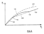
- FIG. 2 shows the ideal characteristic curve of a braking corrector under the reference 220, a curve which has a substantially parabolic shape. It can easily be seen that the addition of the elastic means 6 in the second chamber makes it possible to obtain a better characteristic curve of the corrector which better approaches the ideal curve 220 compared to that 200 of a conventional corrector. Obviously a person skilled in the art will have understood that the rigidity or the elasticity of the annular seal 7 has an important role for the continuity of the characteristic curve.
- the annular seal 7 is made of an elastomer of the styrene-butadian type having a hardness of between 40 and 85 shores at room temperature.
Landscapes
- Engineering & Computer Science (AREA)
- Transportation (AREA)
- Mechanical Engineering (AREA)
- Transmission Of Braking Force In Braking Systems (AREA)
- Braking Systems And Boosters (AREA)
- Golf Clubs (AREA)
- Braking Arrangements (AREA)
Abstract
Description
- La présente invention concerne un correcteur de freinage pour véhicule automobile, du type comprenant un corps percé d'un alésage dans lequel un joint annulaire définit des première et seconde chambres dont la première est reliée à un circuit d'un maître-cylindre et la seconde à au moins un moteur de frein, un piston formant clapet mobile en translation axiale dans une entretoise annulaire en appui contre le joint annulaire, le piston présentant un diamètre supérieur à celui de l'orifice central du joint annulaire qui forme siège de clapet, et étant pourvu d'un poussoir qui traverse le joint annulaire et la première chambre et fait saillie de façon étanche hors du corps.
- Un tel correcteur de freinage est décrit dans IT-B-1 183 952.
- On sait que la courbe caractéristique d'un tel correcteur est constituée par la fonction de la pression de sortie par rapport à la pression d'entrée, c'est à dire la fonction de la pression régnant dans la seconde chambre par rapport à celle régnant dans la première chambre. Cette courbe est constituée par deux segments de droite de pentes différentes reliés en un point nommé "point de coupure" à partir duquel la pression augmente moins vite dans la seconde chambre que dans la première chambre.
- La présente invention a pour but d'ajoindre au correcteur décrit ci-avant, un moyen permettant de mieux approximer la courbe idéale.
- Selon l'invention, on atteint ce but en montant mobile en translation axiale l'ensemble constitué par le joint annulaire et l'entretoise annulaire, et en disposant dans la seconde chambre un moyen élastique confiné entre l'entretoise annulaire et le fond de l'alésage.
- L'invention sera mieux comprise et d'autres buts, avantages et caractéristiques de celle-ci apparaitront plus clairement à la lecture de la description qui suit d'un mode de réalisation préféré à laquelle deux planches de dessins sont joints sur lesquels :
- - la Figure 1 est une vue schématique en coupe d'un correcteur conforme à la présente invention ; et
- - la Figure 2 représente schématiquement la courbe caractéristique d'un correcteur (idéale, avec et sans le moyen selon l'invention).
- En référence maintenant à la Figure 1, on a représenté un correcteur de freinage du type précité qui agit en fonction de la charge du véhicule ainsi équipé.
- De façon connue, ce correcteur comprend un corps 1 dans lequel a été pratiqué un alésage. Un joint annulaire 7 percé d'un orifice central détermine deux chambres dans cet alésage.
- La première chambre 2 est reliée par un conduit 4 à une chambre de pression d'un maître-cylindre, tandis que la seconde chambre 3 est reliée par un conduit 5 à au moins un moteur de frein.
- Le joint annulaire 7 constitue un siège pour un clapet constitué par un piston 8 pourvu d'un poussoir 9. On sait qu'à l'extrémité du poussoir 9 est appliquée une force représentative de la charge du véhicule. Ce poussoir 9 traverse donc l'orifice central du joint annulaire 7, la chambre 2 et un bouchon 12 fermant l'alésage duquel il fait saillie. Le piston 8 est mobile en translation axiale dans une entretoise annulaire 18 qui s'appuie contre le joint annulaire 7. En position de repos, tel que représenté sur la Figure 1, un ressort hélicoïdal 16 disposé dans la première chambre 2 maintient le clapet ouvert en s'appuyant d'une part sur le bouchon 12 et d'autre part sur une butée annulaire 15 dont est pourvu le poussoir 9, cette butée annulaire 15 venant en appui sur le joint annulaire 7 et étant disposée de façon à ce que le piston 8 ne ferme pas l'orifice central du joint annulaire 7.
- Conformément à l'invention, l'ensemble constitué par l'entretoise annulaire 18 et le joint annulaire 7 est monté mobile en translation axiale, et un moyen élastique tel qu'un ressort hélicoïdal 6 est disposé entre l'entretoise annulaire 18 et le fond de l'alésage dans la seconde chambre 3.
- Ainsi, au repos, les chambres 2 et 3 communiquent-elles par l'orifice central du joint annulaire 7. Lorsque la pression du fluide de freinage augmente dans le maître-cylindre, c'est à dire dans la chambre 2, la pression dans un premier temps, augmente identiquement dans la chambre 3 et, par suite, dans les moteurs de freins qui lui sont reliés, puisque les deux chambres communiquent (partie 100 de la courbe représentée Figure 2). Lorsque la pression augmente dans la chambre 2, on atteint le point de coupure 110 pour lequel le clapet se ferme. Le produit de la pression régnant dans les chambres par la section de l'alésage du bouchon 12 est alors égale à la somme de la force externe appliquée au poussoir du piston en fonction de la charge du véhicule et de la force interne exercée par le ressort 16.
- A partir de ce point 110, dans un premier temps une augmentation de la pression dans la première chambre 2 se traduit par un déplacement axial de l'ensemble constitué par le joint annulaire 7, l'entretoise annulaire 18, ce qui est rendu possible du fait de l'élasticité du joint annulaire 7 dont la partie interne reste en appui contre le piston 8 et la partie externe se déplace. Le piston 8 reste immobile et maintient fermé l'orifice central du joint annulaire 7. Ce déplacement axial est obtenu à l'encontre du ressort 6 disposé dans la seconde chambre 3. On a alors une augmentation de la pression dans la seconde chambre 3, fonction du rapport des sections utiles et de la raideur du ressort 6 (partie 120 de la courbe représentée Figure 2).
- Si la pression continue à augmenter dans la chambre 2, on atteint le point 130 de la courbe représentée le ressort 6 est complètement écrasé ; l'entretoise annulaire 18 et, par suite, le joint annulaire 7, sont en butée et ne peuvent plus se déplacer. Par réaction élastique du joint annulaire 7 et sous l'effet de la pression, le piston 8 se déplace encore pour augmenter la pression dans la seconde chambre 3.
- Si la pression dans la première chambre 2 continue à augmenter, on atteint le point 150 de la courbe pour lequel le clapet s'ouvre à nouveau. La caractéristique du correcteur devient alors identique à celle d'un correcteur classique (courbe 200 représentée Figure 2) et fonction seulement du rapport des surfaces utiles, la pression dans la seconde chambre augmentant linéairement mais moins rapidement que celle régnant dans la première chambre.
- Au relâchement de la pédale de frein, les phases décrites précédemment se succèdent dans l'ordre inverse et le correcteur revient au repos comme représenté Figure 1.
- On a représenté Figure 2, la courbe caractéristique idéale d'un correcteur de freinage sous la référence 220, courbe qui a une forme sensiblement parabolique. On constate aisément que l'adjonction du moyen élastique 6 dans la seconde chambre permet d'obtenir une meilleure la courbe caractéristique du correcteur qui approche mieux la courbe idéale 220 par rapport à celle 200 d'un correcteur classique. Bien évidement l'homme du métier aura compris que la rigidité ou l'élasticité du joint annulaire 7 a un rôle important pour la continuité de la courbe caractéristique.
- Selon un mode de réalisation préféré, le joint annulaire 7 est en élastomère du type styrène-butadienne présentant une dureté comprise entre 40 et 85 Shores à température ambiante.
Claims (3)
Applications Claiming Priority (2)
| Application Number | Priority Date | Filing Date | Title |
|---|---|---|---|
| IT8967507A IT1232112B (it) | 1989-06-22 | 1989-06-22 | Correttore di frenatura per un veicolo automobile |
| IT6750789 | 1989-06-22 |
Publications (2)
| Publication Number | Publication Date |
|---|---|
| EP0404617A1 true EP0404617A1 (fr) | 1990-12-27 |
| EP0404617B1 EP0404617B1 (fr) | 1993-12-01 |
Family
ID=11302999
Family Applications (1)
| Application Number | Title | Priority Date | Filing Date |
|---|---|---|---|
| EP90401457A Expired - Lifetime EP0404617B1 (fr) | 1989-06-22 | 1990-05-31 | Correcteur de freinage |
Country Status (7)
| Country | Link |
|---|---|
| US (1) | US5082332A (fr) |
| EP (1) | EP0404617B1 (fr) |
| BR (1) | BR9002911A (fr) |
| DE (1) | DE69004869T2 (fr) |
| IT (1) | IT1232112B (fr) |
| PL (1) | PL163848B1 (fr) |
| YU (1) | YU47770B (fr) |
Cited By (1)
| Publication number | Priority date | Publication date | Assignee | Title |
|---|---|---|---|---|
| FR2690716A1 (fr) * | 1992-04-30 | 1993-11-05 | Bendix Europ Services Tech | Compensateur à plusieur pentes. |
Families Citing this family (1)
| Publication number | Priority date | Publication date | Assignee | Title |
|---|---|---|---|---|
| JPH10181555A (ja) * | 1996-12-25 | 1998-07-07 | Jidosha Kiki Co Ltd | ブレーキ液圧制御弁 |
Citations (5)
| Publication number | Priority date | Publication date | Assignee | Title |
|---|---|---|---|---|
| GB1161829A (en) * | 1965-12-07 | 1969-08-20 | Fiat Spa | Pressure Reducer Device for Hydraulic Brake Mechanisms on Vehicles. |
| DE2638190A1 (de) * | 1976-08-25 | 1978-03-02 | Teves Gmbh Alfred | Drucksteuereinheit fuer hydraulische fahrzeugbremsanlagen |
| EP0046659A1 (fr) * | 1980-08-23 | 1982-03-03 | LUCAS INDUSTRIES public limited company | Moteur hydraulique pour frein à tambour à mâchoire interne d'un véhicule |
| EP0082044A1 (fr) * | 1981-12-11 | 1983-06-22 | Societe De L'usine De La Marque | Régulateur de freinage pour véhicule |
| DE3615154A1 (de) * | 1986-05-05 | 1987-11-12 | Teves Gmbh Alfred | Bremsdruckregelventilanordnung |
Family Cites Families (4)
| Publication number | Priority date | Publication date | Assignee | Title |
|---|---|---|---|---|
| US3526437A (en) * | 1966-06-13 | 1970-09-01 | Bendix Corp | Hold-off valve |
| US3597009A (en) * | 1968-07-11 | 1971-08-03 | Fiat Spa | Pressure reducer devices |
| FR2341465A1 (fr) * | 1976-02-18 | 1977-09-16 | Dba | Correcteur de freinage |
| DE3011633C2 (de) * | 1980-03-26 | 1986-08-21 | Alfred Teves Gmbh, 6000 Frankfurt | Druckminderer für hydraulische Bremskraftanlagen |
-
1989
- 1989-06-22 IT IT8967507A patent/IT1232112B/it active
-
1990
- 1990-05-04 YU YU88090A patent/YU47770B/sh unknown
- 1990-05-31 EP EP90401457A patent/EP0404617B1/fr not_active Expired - Lifetime
- 1990-05-31 DE DE90401457T patent/DE69004869T2/de not_active Expired - Fee Related
- 1990-06-15 BR BR909002911A patent/BR9002911A/pt not_active IP Right Cessation
- 1990-06-19 US US07/541,117 patent/US5082332A/en not_active Expired - Fee Related
- 1990-06-21 PL PL90285730A patent/PL163848B1/pl unknown
Patent Citations (5)
| Publication number | Priority date | Publication date | Assignee | Title |
|---|---|---|---|---|
| GB1161829A (en) * | 1965-12-07 | 1969-08-20 | Fiat Spa | Pressure Reducer Device for Hydraulic Brake Mechanisms on Vehicles. |
| DE2638190A1 (de) * | 1976-08-25 | 1978-03-02 | Teves Gmbh Alfred | Drucksteuereinheit fuer hydraulische fahrzeugbremsanlagen |
| EP0046659A1 (fr) * | 1980-08-23 | 1982-03-03 | LUCAS INDUSTRIES public limited company | Moteur hydraulique pour frein à tambour à mâchoire interne d'un véhicule |
| EP0082044A1 (fr) * | 1981-12-11 | 1983-06-22 | Societe De L'usine De La Marque | Régulateur de freinage pour véhicule |
| DE3615154A1 (de) * | 1986-05-05 | 1987-11-12 | Teves Gmbh Alfred | Bremsdruckregelventilanordnung |
Cited By (4)
| Publication number | Priority date | Publication date | Assignee | Title |
|---|---|---|---|---|
| FR2690716A1 (fr) * | 1992-04-30 | 1993-11-05 | Bendix Europ Services Tech | Compensateur à plusieur pentes. |
| WO1993022167A1 (fr) * | 1992-04-30 | 1993-11-11 | Bendix Europe Services Techniques | Compensateur a plusieurs pentes |
| TR26770A (tr) * | 1992-04-30 | 1995-05-15 | Bendix Europ Services Tech | Cok egimli kompensatör |
| US5451098A (en) * | 1992-04-30 | 1995-09-19 | Alliedsignal Europe Services Techniques | Multislope compensator |
Also Published As
| Publication number | Publication date |
|---|---|
| PL285730A1 (en) | 1991-04-08 |
| YU47770B (sr) | 1996-01-09 |
| YU88090A (sh) | 1994-01-20 |
| DE69004869T2 (de) | 1994-04-14 |
| DE69004869D1 (de) | 1994-01-13 |
| EP0404617B1 (fr) | 1993-12-01 |
| PL163848B1 (pl) | 1994-05-31 |
| IT1232112B (it) | 1992-01-23 |
| US5082332A (en) | 1992-01-21 |
| IT8967507A0 (it) | 1989-06-22 |
| BR9002911A (pt) | 1991-08-20 |
Similar Documents
| Publication | Publication Date | Title |
|---|---|---|
| FR2673410A1 (fr) | Servomoteur d'assistance au freinage a saut reglable et procede de reglage du saut. | |
| EP0340059B1 (fr) | Servomoteur d'assistance au freinage à saut réglable | |
| EP0218510B2 (fr) | Servomoteur d'assistance au freinage | |
| EP0158552B1 (fr) | Servomoteur à dépression d'assistance au freinage | |
| EP0404617B1 (fr) | Correcteur de freinage | |
| EP1600347A1 (fr) | Simulateur d'actionnement de frein, maítre-cylindre pour frein de vehicule automobile, et procede de commande de ce simulateur | |
| FR2658466A1 (fr) | Ensemble d'un servomoteur d'assistance au freinage et d'un maitre cylindre. | |
| EP0335764B1 (fr) | Correcteur de freinage asservi à la charge d'un véhicule en fonction de l'assiette de ce dernier | |
| FR2724356A1 (fr) | Servomoteur pneumatique d'assistance au freinage | |
| FR2663598A1 (fr) | Servomoteur d'assistance a depression. | |
| WO1994001311A1 (fr) | Maitre-cylindre tandem a desequilibre de pressions reduit | |
| EP0991555B1 (fr) | Maitre-cylindre a reaction hydraulique dynamique reglee par une difference de sections | |
| EP0819076B1 (fr) | Maitre-cylindre tandem a etancheite perfectionnee | |
| EP0615500B1 (fr) | Dispositif de commande hydraulique a valve mobile | |
| EP0395462B1 (fr) | Correcteur de freinage | |
| FR2679305A1 (fr) | Servofrein a depression. | |
| EP0463896B1 (fr) | Servofrein pneumatique de type tandem | |
| EP0526274A1 (fr) | Servomoteur double d'assistance au freinage | |
| FR2468016A1 (fr) | Moteur hydraulique | |
| EP0530057B1 (fr) | Correcteur de freinage | |
| FR2696143A1 (fr) | Dispositif de freinage assisté à réaction hydraulique ralentie. | |
| FR2533873A1 (fr) | Dispositif pour surveiller l'etancheite du piston dans un maitre-cylindre de frein | |
| FR2520312A1 (fr) | Contacteur de commande hydromecanique pour installation de reglage d'eclairage a distance de phares de vehicules automobiles | |
| FR2646477A1 (fr) | Servomoteur a depression | |
| FR2566727A1 (fr) | Unite de commande de la pression de freinage |
Legal Events
| Date | Code | Title | Description |
|---|---|---|---|
| PUAI | Public reference made under article 153(3) epc to a published international application that has entered the european phase |
Free format text: ORIGINAL CODE: 0009012 |
|
| AK | Designated contracting states |
Kind code of ref document: A1 Designated state(s): DE FR GB IT |
|
| 17P | Request for examination filed |
Effective date: 19901218 |
|
| 17Q | First examination report despatched |
Effective date: 19920204 |
|
| GRAA | (expected) grant |
Free format text: ORIGINAL CODE: 0009210 |
|
| AK | Designated contracting states |
Kind code of ref document: B1 Designated state(s): DE FR GB IT |
|
| PG25 | Lapsed in a contracting state [announced via postgrant information from national office to epo] |
Ref country code: IT Free format text: LAPSE BECAUSE OF FAILURE TO SUBMIT A TRANSLATION OF THE DESCRIPTION OR TO PAY THE FEE WITHIN THE PRE;WARNING: LAPSES OF ITALIAN PATENTS WITH EFFECTIVE DATE BEFORE 2007 MAY HAVE OCCURRED AT ANY TIME BEFORE 2007. THE CORRECT EFFECTIVE DATE MAY BE DIFFERENT FROM THE ONE RECORDED.SCRIBED TIME-LIMIT Effective date: 19931201 |
|
| GBT | Gb: translation of ep patent filed (gb section 77(6)(a)/1977) |
Effective date: 19931209 |
|
| REF | Corresponds to: |
Ref document number: 69004869 Country of ref document: DE Date of ref document: 19940113 |
|
| RAP2 | Party data changed (patent owner data changed or rights of a patent transferred) |
Owner name: ALLIEDSIGNAL FRENI S.P.A. |
|
| PLBE | No opposition filed within time limit |
Free format text: ORIGINAL CODE: 0009261 |
|
| STAA | Information on the status of an ep patent application or granted ep patent |
Free format text: STATUS: NO OPPOSITION FILED WITHIN TIME LIMIT |
|
| 26N | No opposition filed | ||
| PGFP | Annual fee paid to national office [announced via postgrant information from national office to epo] |
Ref country code: GB Payment date: 19960522 Year of fee payment: 7 |
|
| PGFP | Annual fee paid to national office [announced via postgrant information from national office to epo] |
Ref country code: DE Payment date: 19960528 Year of fee payment: 7 |
|
| PGFP | Annual fee paid to national office [announced via postgrant information from national office to epo] |
Ref country code: FR Payment date: 19960530 Year of fee payment: 7 |
|
| PG25 | Lapsed in a contracting state [announced via postgrant information from national office to epo] |
Ref country code: GB Effective date: 19970531 |
|
| GBPC | Gb: european patent ceased through non-payment of renewal fee |
Effective date: 19970531 |
|
| PG25 | Lapsed in a contracting state [announced via postgrant information from national office to epo] |
Ref country code: FR Free format text: LAPSE BECAUSE OF NON-PAYMENT OF DUE FEES Effective date: 19980130 |
|
| PG25 | Lapsed in a contracting state [announced via postgrant information from national office to epo] |
Ref country code: DE Free format text: LAPSE BECAUSE OF NON-PAYMENT OF DUE FEES Effective date: 19980203 |
|
| REG | Reference to a national code |
Ref country code: FR Ref legal event code: ST |