EP0404657A1 - Vorrichtung zur Bestimmung der Bewegungsrichtung eines bewegbaren Gegenstandes - Google Patents
Vorrichtung zur Bestimmung der Bewegungsrichtung eines bewegbaren Gegenstandes Download PDFInfo
- Publication number
- EP0404657A1 EP0404657A1 EP90401710A EP90401710A EP0404657A1 EP 0404657 A1 EP0404657 A1 EP 0404657A1 EP 90401710 A EP90401710 A EP 90401710A EP 90401710 A EP90401710 A EP 90401710A EP 0404657 A1 EP0404657 A1 EP 0404657A1
- Authority
- EP
- European Patent Office
- Prior art keywords
- movable part
- friction
- range
- cam
- toothing
- Prior art date
- Legal status (The legal status is an assumption and is not a legal conclusion. Google has not performed a legal analysis and makes no representation as to the accuracy of the status listed.)
- Granted
Links
Images

Classifications
-
- G—PHYSICS
- G01—MEASURING; TESTING
- G01P—MEASURING LINEAR OR ANGULAR SPEED, ACCELERATION, DECELERATION, OR SHOCK; INDICATING PRESENCE, ABSENCE, OR DIRECTION, OF MOVEMENT
- G01P13/00—Indicating or recording presence, absence, or direction, of movement
- G01P13/02—Indicating direction only, e.g. by weather vane
- G01P13/04—Indicating positive or negative direction of a linear movement or clockwise or anti-clockwise direction of a rotational movement
Definitions
- the present invention relates to a device for determining the direction of movement of a movable object in rotation or in translation.
- Such a device is capable of numerous applications, in particular in the field of programmers for household appliances which include a block of cams mounted movably for actuating levers for opening or closing electrical contacts.
- a device of the type defined above is for example useful for determining the direction of drive of the cam block, direction unknown when this block is driven by the user of the device, or by a motor whose the starting direction is subject to hazards.
- a device for determining the direction of rotation of a block of cams comprising two cams integral with the block, each of them comprising a large number of actuation teeth of a lever for closing a contact normally. open.
- the two cams are mounted so that their respective teeth are slightly offset from each other.
- One pad of each contact is brought together at a fixed voltage, the other being connected to each of the two inputs of an electronic circuit sensitive to the offset, over time, of the signals applied to it, an offset which depends on the direction of rotation of the cams.
- Such a device is relatively complex, therefore of a high cost price, and of a reliability which sometimes leaves something to be desired. In addition it is bulky.
- information relating to the direction of movement of the cam block is available in the form of an electrical signal. This requires the use of a relay when it is desired to open an electrical connection, for example when the block is driven in one direction, and close it when the block is driven in the other direction.
- the relays are also components of a relatively high cost price, and whose reliability is not perfect.
- European patent No.0 071 501 describes a device in which the useful information is supplied by a moving part, and therefore capable of actuating a contact directly, without using a relay.
- the moving part of this known device is a crown driven in rotation for the moving object, in this case a rotary shaft passing through the crown, thanks to the wedging of one of two rollers arranged between the shaft and the crown.
- the drive range of the crown is limited by the arrival of the latter in a position where the opposing stresses of the two rollers on the crown are balanced.
- This device using rollers which jam to drive the moving part, and which rub on it when it is stationary, is relatively complex, and involves precise machining of the parts, and a judicious choice of materials, in order to achieve to satisfactory reliability.
- the present invention aims to overcome the above drawbacks, by providing a device for determining the direction of training in which, as in that described in the European patent already cited, the useful information is provided by a moving part, and which is simple , robust, reliable and space-saving.
- the subject of the present invention is a device of the type defined above, characterized in that it comprises: a moving part in rotation or in translation over a first range of positions limited by two stops, and coupled by friction to said object, and, - means indicating that of the two stops against which said moving part comes into contact when said object is moving.
- the device of the invention mainly uses simple mechanical elements which give it a low cost price, good robustness, and a reduced size.
- said moving part is provided with coupling means with said object, active over a second range of positions of said moving part, said second range being less than said first range and occupying its central part, so that after a change in the direction of movement of said object, said moving part is driven by said object, first under the effect of friction alone, then positively under the effect of said coupling means, and again under the effect just rubbing.
- the operation is particularly reliable, because over most of its travel, the moving part is positively driven by the moving object, thanks to the coupling means, the friction being used only at the start and in end of stroke, at the start of the stroke to make the coupling means active, and at the end of the stroke to stop making them active, in order to allow the object to move while the moving part is in abutment.
- said moving part is mechanically coupled with a clearance to a control part of said indicator means, so that, when said moving part is driven by said object under the effect of the sole friction immediately after a change of direction of said object, said control part remains stationary.
- control part has a significant effort to provide when the moving part passes from one end to the other of its travel, for example to actuate a switch, without risk of immobilization.
- the force to be supplied by the control part is transferred to the mobile part when the latter is positively driven by the coupling means, and not when the latter is driven under the effect of friction alone.
- the friction function is limited to a small movement of the moving part alone.
- said object is provided with a toothing with which a toothed pinion cooperates rotatably mounted about an axis, said movable part is pivotally mounted around the same axis, and there is provided on said toothed pinion a crown which cooperates by friction with a cylindrical part provided on said movable part, or vice versa, and means are provided for elastic return of said crown against said cylindrical part.
- Such an embodiment ensures good friction stability over time.
- said coupling means comprise a tooth intended to cooperate with said toothing of said object.
- Such an embodiment is particularly simple.
- said indicator means comprise a lever opening and closing an electrical switch
- said control part is a cam which moves said lever and the device is used in a programmer for appliance type appliance, in which the switch authorizes the supply of electrical energy of the main organs of said apparatus.
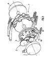
- a programmer for household appliances for example for a washing machine or dishes, comprises a block of cams 7, intended to selectively operate levers for opening and closing contacts of feeding of the various organs of the apparatus.
- the cam block 7 can be driven in rotation either by means of a button 6 operated by the user when he selects one of the possible programs, or by means of a reduction gear 2 driven by him. -even by a motor 1, to run a particular program for operating the device.
- a device for determining the amplitude of the displacements of the cam block, for example by counting the number of elementary steps taken, and an electronic circuit which stores the amplitude and the direction of the displacements from a determined reference position, and which is therefore able to determine at any time the position of the cam block.
- the reduction gear 2 drives the block 7 by means of a toothing 18 provided on a crown 3 formed on a disc integral with the block 7.
- a toothed pinion 9, mounted to rotate around an axis parallel to the axis of the cam block 7 cooperates with the toothing 18 and is therefore permanently driven by the crown 3.
- a movable part 10 is pivotally mounted on the same axis as the toothed pinion 9, with which it cooperates by friction, in a manner which will be better understood below.
- the moving part 10 comprises a single tooth 11 capable of cooperating with the toothing 18, and it is coupled with a clearance to a cam 12 for controlling a lever 15 which opens and closes an electrical switch 13 of which only the flexible blades carrying the studs are visible in FIG. 1.
- the clearance between the movable part 10 and the cam 12 is obtained by a radial lug 14 integral with the movable part 10 which is engaged in a recess 19, in the form of an angular sector appreciably wider than the radial lug 14, recess 19 formed in the cam 12.
- FIG. 3 a shows one of the positions ends of the moving part 10, the extreme position in which the radial lug 14 abuts against one end of the recess 19, and the lug 16 cooperates with the stop 172.
- FIG. 3 c shows the other extreme position of the moving part 10, extreme position in which the radial lug 14 is in abutment against the other end of the recess 19, and the lug 16 cooperates with the abutment 171. It can therefore be considered that the moving part 10 can occupy a range of positions limited by two stops.
- the moving part 10 comprises two cylindrical parts of different diameters.
- a first part 100 having the largest diameter, carries on one side the radial lug 14, and on the other the tooth 11.
- a second part 101 having the smallest diameter, extends the part 100 on the side of the tooth 11, and serves as a shaft for the toothed pinion 9.
- the cylindrical part 101 has an axial dimension greater than that of the toothed pinion 9, so that, when the latter is mounted on the cylindrical part 101, the latter protrudes from the body of the toothed pinion 9.
- the latter is provided with a crown 91 comprising two wings, resiliently recalled by a ring 92 against the cylindrical part 101 projecting, so as to ensure friction between the crown 91 and the projecting part 101, that is to say between the pinion 9 and the moving part 10, friction which thus remains relatively stable over time.
- the diameter of the cylindrical part 100 is equal to the inside diameter of the teeth of the pinion 9, and the tooth 11 is of substantially identical shape to that of the teeth of the teeth of the pinion 9.
- the assembly is mounted against the crown. 3 so that the tooth 11 and the pinion 9 can cooperate at the same time with the toothing 18.
- the tooth 11 allows the teeth 18 and the moving part 10 to be coupled, this coupling being active over a limited range of positions of the moving part 10, range obviously less than that which has been defined and the ends of which correspond to FIGS. 3 a and 3 c , but occupying the central part of this range.
- the tooth 11 does not cooperate with the toothing 18, while in FIG. 3 b , which represents an intermediate position, the tooth 11 is engaged in the toothing 18.
- the device which has just been described operates as follows, with reference mainly to FIGS. 3.
- the device then arrives in the position described with reference to FIG. 3c , the last part of the movement of the movable part 10 and of the cam 12 being again effected under the action of friction alone, which does not pose any problem. , since there is no more effort to be made to operate the contact 13.
- lever 15 and the electrical switch 13 indicate that of the two stops against which the moving part 10 comes into contact when the disc carrying the crown 3 moves.
- the switch 13 may be the switch says "general" which authorizes the supply of electrical energy to the main organs of the device.
- the friction is obtained by friction of the crown 91, secured to the pinion 9 on the cylindrical part 101, secured to the moving part 10.
- the scope of the present application is not limited to the description which has just been made, nor the application of the device of the invention to programmers for household appliances.
- the device of the invention can be used to determine the direction of movement of any object capable of moving in one direction or the other.
- the above description relates to a mobile object in rotation, but the skilled person is able to transpose the device of the invention for a mobile object in translation.
- the device can take many forms.
- the shape and the position of the cam 12 and of the lever 15 have been deliberately varied.
Landscapes
- Physics & Mathematics (AREA)
- General Physics & Mathematics (AREA)
- Transmission Devices (AREA)
- Rotary Switch, Piano Key Switch, And Lever Switch (AREA)
Applications Claiming Priority (2)
| Application Number | Priority Date | Filing Date | Title |
|---|---|---|---|
| FR8908172A FR2648563B1 (fr) | 1989-06-20 | 1989-06-20 | Dispositif de determination du sens de deplacement d'un objet mobile |
| FR8908172 | 1989-06-20 |
Publications (2)
| Publication Number | Publication Date |
|---|---|
| EP0404657A1 true EP0404657A1 (de) | 1990-12-27 |
| EP0404657B1 EP0404657B1 (de) | 1993-10-13 |
Family
ID=9382922
Family Applications (1)
| Application Number | Title | Priority Date | Filing Date |
|---|---|---|---|
| EP19900401710 Expired - Lifetime EP0404657B1 (de) | 1989-06-20 | 1990-06-19 | Vorrichtung zur Bestimmung der Bewegungsrichtung eines bewegbaren Gegenstandes |
Country Status (4)
| Country | Link |
|---|---|
| EP (1) | EP0404657B1 (de) |
| BR (1) | BR8905467A (de) |
| DE (1) | DE69003884T2 (de) |
| FR (1) | FR2648563B1 (de) |
Cited By (1)
| Publication number | Priority date | Publication date | Assignee | Title |
|---|---|---|---|---|
| US20190094020A1 (en) * | 2017-09-22 | 2019-03-28 | Goodrich Corporation | Wheel speed and direction sensor |
Families Citing this family (1)
| Publication number | Priority date | Publication date | Assignee | Title |
|---|---|---|---|---|
| DE19546595A1 (de) * | 1995-12-13 | 1997-06-19 | Siemens Ag | Drehzahl- und/oder Drehrichtung-Sensorvorrichtung |
Citations (4)
| Publication number | Priority date | Publication date | Assignee | Title |
|---|---|---|---|---|
| DE1498191A1 (de) * | 1965-04-07 | 1970-02-19 | Siemens Ag | Anordnung zur Bestimmung des Drehweges und der Drehrichtung der Achse eines Mess- oder Zaehlorgans |
| US3614492A (en) * | 1970-06-10 | 1971-10-19 | Controls Co Of America | Bidirectional motor |
| EP0071501A1 (de) * | 1981-07-23 | 1983-02-09 | Mors | Winkelmässig begrenzte Antriebskupplung, um an eine Antriebswelle ein Hilfssteuermittel in zwei Stellungen der Drehrichtung der Welle folgend, zu kuppeln |
| EP0216556A2 (de) * | 1985-09-09 | 1987-04-01 | Philips Home Products, Inc. | Kupplung mit verzögertem Antrieb |
-
1989
- 1989-06-20 FR FR8908172A patent/FR2648563B1/fr not_active Expired - Fee Related
- 1989-10-26 BR BR8905467A patent/BR8905467A/pt unknown
-
1990
- 1990-06-19 DE DE1990603884 patent/DE69003884T2/de not_active Expired - Fee Related
- 1990-06-19 EP EP19900401710 patent/EP0404657B1/de not_active Expired - Lifetime
Patent Citations (4)
| Publication number | Priority date | Publication date | Assignee | Title |
|---|---|---|---|---|
| DE1498191A1 (de) * | 1965-04-07 | 1970-02-19 | Siemens Ag | Anordnung zur Bestimmung des Drehweges und der Drehrichtung der Achse eines Mess- oder Zaehlorgans |
| US3614492A (en) * | 1970-06-10 | 1971-10-19 | Controls Co Of America | Bidirectional motor |
| EP0071501A1 (de) * | 1981-07-23 | 1983-02-09 | Mors | Winkelmässig begrenzte Antriebskupplung, um an eine Antriebswelle ein Hilfssteuermittel in zwei Stellungen der Drehrichtung der Welle folgend, zu kuppeln |
| EP0216556A2 (de) * | 1985-09-09 | 1987-04-01 | Philips Home Products, Inc. | Kupplung mit verzögertem Antrieb |
Cited By (1)
| Publication number | Priority date | Publication date | Assignee | Title |
|---|---|---|---|---|
| US20190094020A1 (en) * | 2017-09-22 | 2019-03-28 | Goodrich Corporation | Wheel speed and direction sensor |
Also Published As
| Publication number | Publication date |
|---|---|
| DE69003884D1 (de) | 1993-11-18 |
| EP0404657B1 (de) | 1993-10-13 |
| FR2648563A1 (fr) | 1990-12-21 |
| DE69003884T2 (de) | 1994-05-19 |
| BR8905467A (pt) | 1991-04-23 |
| FR2648563B1 (fr) | 1993-01-22 |
Similar Documents
| Publication | Publication Date | Title |
|---|---|---|
| EP2365407B1 (de) | Vorrichtung zum Aufziehen und zur Zeiteinstellung für ein Uhrwerk | |
| EP1081563B1 (de) | Uhr der Armbanduhrenbauart | |
| EP2085832B1 (de) | Chronographenvorrichtung mit Reibungskupplung | |
| FR2745059A1 (fr) | Actionneur de vanne | |
| WO2014166798A2 (fr) | Mecanisme de selection et d'actionnement des fonctions d'un mouvement horloger | |
| CH709654B1 (fr) | Bascule d'horlogerie et mécanisme de correction rapide comportant une telle bacule. | |
| EP3602202A1 (de) | Vorrichtung zur einstellung von funktionen einer uhr | |
| EP0404657B1 (de) | Vorrichtung zur Bestimmung der Bewegungsrichtung eines bewegbaren Gegenstandes | |
| FR2564921A1 (fr) | Dispositif pour maintenir en permanence une butee de debrayage en appui sur un mecanisme d'embrayage | |
| WO2001088633A1 (fr) | Dispositif de commande a poussoir pour montre | |
| EP1684133A2 (de) | Uhrwerk | |
| CH702841A1 (fr) | Dispositif correcteur multifonction et pièce d'horlogerie comprenant un tel dispositif correcteur. | |
| FR2509517A1 (fr) | Dispositif de commutation a depassement comportant un mecanisme de transmission a came et a lame pivotante | |
| EP0404658B1 (de) | Programmschalteinrichtung, insbesondere für elektrisches Haushaltsgerät, aus zwei in einer Richtung gekuppelten Teilen | |
| EP1186809B1 (de) | Getriebe mit Schaltaktuator | |
| FR2544098A1 (fr) | Programmateur | |
| EP0630495B1 (de) | Betätigungsvorrichtung für z.b.kupplungs- oder getriebeeinheit | |
| EP0323343B1 (de) | Programmschalteinrichtung für Waschmaschinen | |
| CH702802A2 (fr) | Dispositif de commande de remontage et de mise à l'heure pour un mouvement d'horlogerie. | |
| EP0518768B1 (de) | Schaltgerät für die Programmschalteinrichtung eines elektrischen Haushaltgerät | |
| CH710892B1 (fr) | Mécanisme de chronographe pour mouvement horloger. | |
| FR3116029A1 (fr) | Capteur de position de siège à réducteur à joint de Oldham | |
| CH698141B1 (fr) | Mouvement d'horlogerie mécanique. | |
| FR2896479A1 (fr) | Boite de vitesses, notamment pour cycle | |
| FR2587835A1 (fr) | Dispositif d'affichage a preselection pour programmateur |
Legal Events
| Date | Code | Title | Description |
|---|---|---|---|
| PUAI | Public reference made under article 153(3) epc to a published international application that has entered the european phase |
Free format text: ORIGINAL CODE: 0009012 |
|
| AK | Designated contracting states |
Kind code of ref document: A1 Designated state(s): DE ES FR IT |
|
| 17P | Request for examination filed |
Effective date: 19910627 |
|
| 17Q | First examination report despatched |
Effective date: 19920527 |
|
| GRAA | (expected) grant |
Free format text: ORIGINAL CODE: 0009210 |
|
| AK | Designated contracting states |
Kind code of ref document: B1 Designated state(s): DE ES FR IT |
|
| PG25 | Lapsed in a contracting state [announced via postgrant information from national office to epo] |
Ref country code: ES Free format text: THE PATENT HAS BEEN ANNULLED BY A DECISION OF A NATIONAL AUTHORITY Effective date: 19931013 |
|
| REF | Corresponds to: |
Ref document number: 69003884 Country of ref document: DE Date of ref document: 19931118 |
|
| ITF | It: translation for a ep patent filed | ||
| RAP2 | Party data changed (patent owner data changed or rights of a patent transferred) |
Owner name: CROUZET ELECTROMENAGER |
|
| PLBE | No opposition filed within time limit |
Free format text: ORIGINAL CODE: 0009261 |
|
| STAA | Information on the status of an ep patent application or granted ep patent |
Free format text: STATUS: NO OPPOSITION FILED WITHIN TIME LIMIT |
|
| 26N | No opposition filed | ||
| REG | Reference to a national code |
Ref country code: FR Ref legal event code: CD |
|
| PGFP | Annual fee paid to national office [announced via postgrant information from national office to epo] |
Ref country code: FR Payment date: 19980625 Year of fee payment: 9 |
|
| PGFP | Annual fee paid to national office [announced via postgrant information from national office to epo] |
Ref country code: DE Payment date: 19990617 Year of fee payment: 10 |
|
| PG25 | Lapsed in a contracting state [announced via postgrant information from national office to epo] |
Ref country code: FR Free format text: THE PATENT HAS BEEN ANNULLED BY A DECISION OF A NATIONAL AUTHORITY Effective date: 19990630 |
|
| REG | Reference to a national code |
Ref country code: FR Ref legal event code: ST |
|
| PG25 | Lapsed in a contracting state [announced via postgrant information from national office to epo] |
Ref country code: DE Free format text: LAPSE BECAUSE OF NON-PAYMENT OF DUE FEES Effective date: 20010403 |
|
| PG25 | Lapsed in a contracting state [announced via postgrant information from national office to epo] |
Ref country code: IT Free format text: LAPSE BECAUSE OF NON-PAYMENT OF DUE FEES;WARNING: LAPSES OF ITALIAN PATENTS WITH EFFECTIVE DATE BEFORE 2007 MAY HAVE OCCURRED AT ANY TIME BEFORE 2007. THE CORRECT EFFECTIVE DATE MAY BE DIFFERENT FROM THE ONE RECORDED. Effective date: 20050619 |