EP0405073A2 - Sécheur d'air pour une installation d'air comprimé comprenant au moins un réservoir de stockage d'air et chargeable par un compresseur, en particulier pour une installation de freins à air comprimé de véhicules - Google Patents
Sécheur d'air pour une installation d'air comprimé comprenant au moins un réservoir de stockage d'air et chargeable par un compresseur, en particulier pour une installation de freins à air comprimé de véhicules Download PDFInfo
- Publication number
- EP0405073A2 EP0405073A2 EP90106760A EP90106760A EP0405073A2 EP 0405073 A2 EP0405073 A2 EP 0405073A2 EP 90106760 A EP90106760 A EP 90106760A EP 90106760 A EP90106760 A EP 90106760A EP 0405073 A2 EP0405073 A2 EP 0405073A2
- Authority
- EP
- European Patent Office
- Prior art keywords
- air
- piston
- regeneration
- compressed air
- link
- Prior art date
- Legal status (The legal status is an assumption and is not a legal conclusion. Google has not performed a legal analysis and makes no representation as to the accuracy of the status listed.)
- Granted
Links
Images

Classifications
-
- B—PERFORMING OPERATIONS; TRANSPORTING
- B01—PHYSICAL OR CHEMICAL PROCESSES OR APPARATUS IN GENERAL
- B01D—SEPARATION
- B01D53/00—Separation of gases or vapours; Recovering vapours of volatile solvents from gases; Chemical or biological purification of waste gases, e.g. engine exhaust gases, smoke, fumes, flue gases, aerosols
- B01D53/26—Drying gases or vapours
- B01D53/261—Drying gases or vapours by adsorption
-
- B—PERFORMING OPERATIONS; TRANSPORTING
- B60—VEHICLES IN GENERAL
- B60T—VEHICLE BRAKE CONTROL SYSTEMS OR PARTS THEREOF; BRAKE CONTROL SYSTEMS OR PARTS THEREOF, IN GENERAL; ARRANGEMENT OF BRAKING ELEMENTS ON VEHICLES IN GENERAL; PORTABLE DEVICES FOR PREVENTING UNWANTED MOVEMENT OF VEHICLES; VEHICLE MODIFICATIONS TO FACILITATE COOLING OF BRAKES
- B60T17/00—Component parts, details, or accessories of power brake systems not covered by groups B60T8/00, B60T13/00 or B60T15/00, or presenting other characteristic features
- B60T17/002—Air treatment devices
- B60T17/004—Draining and drying devices
Definitions
- the invention relates to an air dryer according to the preamble of claim 1.
- Air dryers are used in compressed air braking systems to clean and dry the air conveyed by a compressor to regulate the operating pressure in the storage tanks. When installing the air dryer, drainage systems and additional frost protection devices are not required.
- the air is dried by means of adsorption in a molecular sieve, which is formed by a drying agent in the form of granules.
- a drying agent in the form of granules.
- part of the dried air is expanded and passed through the desiccant in the opposite direction.
- the partial pressure of the water vapor in the regeneration air drops, i.e. extremely dry air is formed, which means that the regeneration air is able to absorb the moisture contained in the drying agent.
- the dry air used for regeneration can be taken from a regeneration air tank, but it can also be supplied from the compressed air system to be supplied with compressed air. Solutions are known in which the required amount of regeneration air is controlled depending on the pressure. This means that with a pressure regulator switching range of usually 1 bar, a pressure drop of approximately 0.3 bar must be regulated for the amount of regeneration air flowing back from the compressed air system. Even when using relatively large control surfaces in control devices of this type, experience has shown that this type of control has a high degree of inaccuracy.
- Regeneration devices are also known in which the amount of regeneration air is controlled via a pneumatic time switch attached to the air dryer. It is necessary to adjust the amount of regeneration air to the volume of the brake system using an adjustable nozzle. This increases the required variety of types on the air dryer, i.e. Regeneration devices of the type mentioned with different nozzles are required for different volumes of brake systems.
- the object of the invention is to design an air dryer of the generic type in such a way that the regeneration device is able, independently of the size of the compressed air system to be charged, to regulate the required amount of regeneration air automatically.
- the switch With the help of the switch, it is possible to provide the necessary regeneration air regardless of the compressed air system to be charged, e.g. the vehicle's brake system, since within the available switching range, depending on the system volume, the amount of regeneration air available for the desiccant in the drying cartridge is available is required. There is a direct dependency on the system volume and the air flowing back from the system during the switching period of the pressure regulator for the regeneration of the desiccant.
- the device for controlling the regeneration opens the connection from the compressed air system into the desiccant of the air dryer in precisely adjustable steps by means of the link-controlled valve tappet;
- slot guides are provided on the link, which allow the switching pressure of the pressure regulator integrated on the air dryer housing to take effect for the purpose of opening the regeneration air connection when the link has been rotated by a predetermined angular distance, that is to say actuated by predetermined cycles.
- an air dryer is shown in partial sectional view, which is used to clean and dry the air conveyed by a compressor.
- the air dryer is provided with a housing 1 on which a drying cartridge 3 is seated.
- the drying cartridge is provided in a known manner with a ring filter 5 and a drying agent 7; it is, for example, a granular, highly porous desiccant that is able to bind water vapor on its surface.
- the housing 1 leads an input port 9 to which the compressor (not shown) is connected; the input terminal 9 is over a (not shown) connection to the chamber 11 immediately below the ring filter 5 of the drying cartridge 3 in connection.
- Compressed air conveyed by the compressor enters the chamber 11 from the inlet connection 9, passes through openings 13 on the underside of the drying cartridge 3 and is conducted into the area of the ring filter 5.
- Compressed air freed of impurities, such as oil coal and oil is diverted in the ring filter 5 on the top (not shown) of the drying cartridge and then directed downwards by the drying agent 7.
- the air dried in this way passes along in the arrow representation shown in the drawing into a further chamber 15, from which it passes after passing through the check valve 17 shown in the drawing into the outlet port 19.
- the output connection 19 is connected to the system to be supplied with compressed air, for example to the air reservoir of the brake system of the vehicle.
- a housing 21 is also contained in the housing 1, to which a pressure regulator (not shown) integrated in the housing and having a mode of operation known per se is connected.
- the pressure regulator becomes effective when the cut-off pressure of the compressed air system is reached and feeds the channel 21 with a switching pressure which is able to act on the piston 23 of a blow-off valve 2S.
- the blow-off valve 25 carries on the shaft 27 connected to the piston 23 a valve plate 29 which acts against a seat 31 fixed to the housing and blocks the chamber 33 located above the valve plate 29 in normal operation from the chamber 35 which is connected to outside air.
- a silencer 36 can be provided, which passes through the air.
- the channel 21 is further connected by means of the dash-dotted connection 37 to a space 39 which delimits a piston 43 which is displaceable in a switch housing 41.
- the piston 43 is part of a pneumatic-mechanical switch 45, by means of which the time of regeneration of the desiccant is controlled by air from the consumer system.
- the piston 43 acts against a spring 47, which is supported on the inside of the switch housing 41, the space 49 receiving the spring being connected to the outside air via a bore 51.
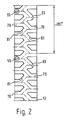
- the piston 43 is displaceable on a central extension 53 with mutual sealing of the spaces 39 and 49 and engages by means of radially inwardly extending pins 55 in a link 57 which rotates but is axially secured at the right-hand end of an extension extending in the interior of the extension 53
- Valve tappet 59 is guided.
- the valve tappet 59 monitors with its left-hand end 61, which carries a sealing element, a connection between a bore 63 connected to the outlet connection 19 and a channel 65, which in turn is connected via a bore 67 to the chamber 15 located centrally below the drying cartridge 3.
- the valve tappet 59 is thus able to produce a free connection between the outlet connection 19 and the chamber 15 and accordingly with the interior of the drying cartridge 3 in the manner described below.
- the bore 63 and the channel 65 are closed at their end opening towards the outside of the housing 1 by means of sealing elements 71 and 73.
- the link 57 is arranged at the right end of the valve tappet as shown and is axially immovably supported by means of a ring 75, a spring 77 being supported between the ring 75 and the inside of the switch housing in such a way that it tries the valve tappet 59 to face to the left move.
- 57 slots 79 are formed as backdrop tracks on the outer circumference of the backdrop. In these slots 79, the pins 55 of the Slide piston 43 when the piston makes longitudinal and forward movements on the extension 53.
- the slots 79 intersect at an angle in the middle of the backdrop, ie bevels 81 are provided which come into contact with the piston 43, ie the pins 55, with each axial movement such that the backdrop is subsequently rotated in one direction.
- the slots 79 are distributed over the circumference of the link body in such a way that three unactuated positions correspond to one actuated position, that is to say the driving position, in other words, the angular distance between two stops 83 is 180 °.
- the air conveyed by the (not shown) compressor flows through the inlet connection 9 into the ring filter 5, from there into the drying agent 7 located inside the drying cartridge, and reaches the chamber 69 located centrally below the drying chamber there, after passing through the pressure-dependent check valve 17, the air flows into the outlet connection 19 and thus into the compressed air system to be charged, for example into the air reservoir of the brake system of a vehicle.
- the air is freed of impurities such as coal and oil in a known manner; it is also cooled in the ring filter. Thereby some of the water already condenses in the ring filter and, after passing through the connection between the chamber 11 and the chamber 33, collects in it.
- the actual drying takes place within the desiccant 7, ie the compressed air passing through the check valve 17 reaches the air reservoir of the brake system as dried air.
- the pressure regulator integrated in the housing 1 and acted upon by the pressure of the brake system opens the blow-off valve 25 by means of the switching pressure which it controls in the channel 21.
- the piston 23 acted upon by the regulator switching pressure lifts the valve plate 29 from its seat 31, so that the compressor via the input connection and the chamber 33 now into the chamber 35, i.e. promotes in the outside air.
- condensed water that has collected in the chamber 33 and a large part of the filtered out impurities are also eliminated.
- the check valve 17 remains closed due to the pressure reduction.
- the switching pressure prevailing in the channel 21 after the pressure regulator responds due to the existing connection via the bore 63, also acts in the space 39, ie on the left side of the piston 43 as shown.
- the piston 43 is pushed to the right by this pressure against the force of the spring 47 directed shifted, with the result that the pins 55 pass through the link 57 in the aforementioned manner and in the course of this axial movement perform a partial rotation of the link 57. If the pins 55 are within a free slot, there is no axial movement of the valve lifter 59.
- the pressure regulator (not shown) becomes active again, ie the compressed air connection to channel 21 is cut off and the channel is vented.
- the switching process described above is carried out three times, ie there are no regeneration in the blow-off phase during three switching cycles corresponding to three switching positions of the switch 45. Only when the pins 55 have reached their stop position on the stop 83, that is to say when the fourth switching cycle has been reached, the link 57 is taken along when the piston 43 is moved to the right and subsequently the connection between the bore 63 and the channel 65 becomes open.
- the blow-off valve is open at the same time, ie when the pressure in the drying cartridge 3 is reduced, air now flows from the brake system, that is to say from the air reservoir with the check valve 17 remaining in the closed position, via the aforementioned connection 63, 65, 67 into the chamber 15 and passes through the desiccant 7.
- the air the compressed air system relaxes in the moist desiccant and thereby removes the bound water before it reaches the outside via the ring filter 5 and the blow-off valve together with the compressed air of the still conveying compressor.
- the pressure regulator becomes effective again, i.e. the blow-off valve moves into the closed position and the piston 43 returns to the left end position shown in the illustration the consequence that the regeneration air connection between the bore 63 and the channel 65 is closed.
- the regeneration thus takes place during the fourth switching cycle of the backdrop, that is to say after the backdrop has been rotated by 180 °.
- the backdrop can be designed in any way, such that the regeneration is carried out during every third switching cycle, etc.
- the main advantage of the device described above is that it works automatically regardless of the size of the system, i.e. the regeneration phase adapts to its duration after the drying phase, since in the open position of the valve tappet a quantity of regeneration air corresponding to the pressure regulator switching range and the system volume the desiccant flows into the atmosphere.
- the duration of the regeneration phase is therefore a direct measure of the size of the compressed air system.
Landscapes
- Engineering & Computer Science (AREA)
- Chemical & Material Sciences (AREA)
- Transportation (AREA)
- Mechanical Engineering (AREA)
- Analytical Chemistry (AREA)
- General Chemical & Material Sciences (AREA)
- Oil, Petroleum & Natural Gas (AREA)
- Chemical Kinetics & Catalysis (AREA)
- Valves And Accessory Devices For Braking Systems (AREA)
- Drying Of Gases (AREA)
- Filling Or Discharging Of Gas Storage Vessels (AREA)
Applications Claiming Priority (2)
| Application Number | Priority Date | Filing Date | Title |
|---|---|---|---|
| DE3920489A DE3920489A1 (de) | 1989-06-22 | 1989-06-22 | Lufttrockner fuer von einem kompressor aufladbare, wenigstens einen luftvorratsbehaelter aufweisende durckluftanlagen, insbesondere durckluftbremsanlagen von fahrzeugen |
| DE3920489 | 1989-06-22 |
Publications (3)
| Publication Number | Publication Date |
|---|---|
| EP0405073A2 true EP0405073A2 (fr) | 1991-01-02 |
| EP0405073A3 EP0405073A3 (en) | 1992-03-18 |
| EP0405073B1 EP0405073B1 (fr) | 1994-12-14 |
Family
ID=6383356
Family Applications (1)
| Application Number | Title | Priority Date | Filing Date |
|---|---|---|---|
| EP90106760A Expired - Lifetime EP0405073B1 (fr) | 1989-06-22 | 1990-04-09 | Sécheur d'air pour une installation d'air comprimé comprenant au moins un réservoir de stockage d'air et chargeable par un compresseur, en particulier pour une installation de freins à air comprimé de véhicules |
Country Status (4)
| Country | Link |
|---|---|
| EP (1) | EP0405073B1 (fr) |
| AT (1) | ATE115475T1 (fr) |
| DE (2) | DE3920489A1 (fr) |
| HU (1) | HU214617B (fr) |
Cited By (7)
| Publication number | Priority date | Publication date | Assignee | Title |
|---|---|---|---|---|
| EP0530019A3 (fr) * | 1991-08-30 | 1993-03-10 | Knorr-Bremse Systems for Commercial Vehicles Limited | Secheurs de gaz |
| EP0537483A1 (fr) * | 1991-10-15 | 1993-04-21 | KNORR-BREMSE SYSTEME FÜR NUTZFAHRZEUGE GmbH | Sécheur d'air pour installation d'air comprimé chargeable par un compresseur, en particulier pour installation de freins à air comprimé de véhicules |
| WO1994007726A1 (fr) * | 1992-09-30 | 1994-04-14 | Tibor Gergely | Systeme de regeneration de secheurs d'air pour compresseurs |
| US5458676A (en) * | 1994-04-28 | 1995-10-17 | Alliedsignal Truck Brake Systems Company | Pressure differential control valve for compressed air system |
| WO1997001473A1 (fr) * | 1995-06-27 | 1997-01-16 | Robert Bosch Gmbh | Dispositif de commande en fonction du temps de la duree de regeneration d'un deshumidificateur d'air |
| US6786953B2 (en) * | 2002-07-26 | 2004-09-07 | Bendix Commercial Vehicle Systems Llc | Spin-on desiccant cartridge with integral oil removal filter |
| CN104349956A (zh) * | 2012-04-13 | 2015-02-11 | 克诺尔商用车制动系统有限公司 | 包括具有膜片的再生空气开关装置的空气干燥器 |
Families Citing this family (2)
| Publication number | Priority date | Publication date | Assignee | Title |
|---|---|---|---|---|
| DE4429822C2 (de) * | 1994-08-23 | 1998-02-19 | Mann & Hummel Filter | Vorrichtung zum Abscheiden von Ölaerosol aus Luft |
| DE19911741B4 (de) * | 1999-03-16 | 2008-07-31 | Knorr-Bremse Systeme für Nutzfahrzeuge GmbH | Vorrichtung und Verfahren zur Luftaufbereitung, insbesondere für pneumatische Bremsanlagen von Kraftfahrzeugen |
Family Cites Families (4)
| Publication number | Priority date | Publication date | Assignee | Title |
|---|---|---|---|---|
| DE3011725C2 (de) * | 1980-03-26 | 1982-09-16 | Knorr-Bremse GmbH, 8000 München | Lufttrockner für eine Druckluftanlage |
| US4336042A (en) * | 1980-10-14 | 1982-06-22 | Graham-White Sales Corporation | Canister-compactor assembly |
| DE3207052A1 (de) * | 1982-02-26 | 1983-09-08 | Knorr-Bremse GmbH, 8000 München | Gesteuertes entwaesserungsventil fuer druckluftanlagen |
| IT1214386B (it) * | 1987-09-29 | 1990-01-18 | Magneti Marelli Spa | Dispositivo di controllo della rigenerazione dell elemento filtrante di un depuratore per un impianto pneumatico di frenatura per autoveicoli |
-
1989
- 1989-06-22 DE DE3920489A patent/DE3920489A1/de not_active Ceased
-
1990
- 1990-04-09 AT AT90106760T patent/ATE115475T1/de active
- 1990-04-09 DE DE59007985T patent/DE59007985D1/de not_active Expired - Fee Related
- 1990-04-09 EP EP90106760A patent/EP0405073B1/fr not_active Expired - Lifetime
- 1990-06-21 HU HU903944A patent/HU214617B/hu not_active IP Right Cessation
Cited By (11)
| Publication number | Priority date | Publication date | Assignee | Title |
|---|---|---|---|---|
| EP0530019A3 (fr) * | 1991-08-30 | 1993-03-10 | Knorr-Bremse Systems for Commercial Vehicles Limited | Secheurs de gaz |
| EP0537483A1 (fr) * | 1991-10-15 | 1993-04-21 | KNORR-BREMSE SYSTEME FÜR NUTZFAHRZEUGE GmbH | Sécheur d'air pour installation d'air comprimé chargeable par un compresseur, en particulier pour installation de freins à air comprimé de véhicules |
| DE4134115A1 (de) * | 1991-10-15 | 1993-04-22 | Knorr Bremse Ag | Lufttrockner fuer von einem kompressor aufladbare druckluftanlagen, insbesondere druckluftbremsanlagen von fahrzeugen |
| WO1994007726A1 (fr) * | 1992-09-30 | 1994-04-14 | Tibor Gergely | Systeme de regeneration de secheurs d'air pour compresseurs |
| US5458676A (en) * | 1994-04-28 | 1995-10-17 | Alliedsignal Truck Brake Systems Company | Pressure differential control valve for compressed air system |
| WO1997001473A1 (fr) * | 1995-06-27 | 1997-01-16 | Robert Bosch Gmbh | Dispositif de commande en fonction du temps de la duree de regeneration d'un deshumidificateur d'air |
| US6786953B2 (en) * | 2002-07-26 | 2004-09-07 | Bendix Commercial Vehicle Systems Llc | Spin-on desiccant cartridge with integral oil removal filter |
| US6951581B2 (en) * | 2002-07-26 | 2005-10-04 | Bendix Commercial Vehicle Systems Llc | Spin-on desiccant cartridge with integral oil removal filter |
| CN104349956A (zh) * | 2012-04-13 | 2015-02-11 | 克诺尔商用车制动系统有限公司 | 包括具有膜片的再生空气开关装置的空气干燥器 |
| JP2015515371A (ja) * | 2012-04-13 | 2015-05-28 | クノル−ブレムゼ ジステーメ フューア ヌッツファールツォイゲ ゲゼルシャフト ミット ベシュレンクテル ハフツングKnorr−Bremse Systeme fuer Nutzfahrzeuge GmbH | ダイヤフラムを有する再生空気切換装置を備えたエアドライヤ |
| CN104349956B (zh) * | 2012-04-13 | 2017-06-30 | 克诺尔商用车制动系统有限公司 | 包括具有膜片的再生空气开关装置的空气干燥器 |
Also Published As
| Publication number | Publication date |
|---|---|
| EP0405073A3 (en) | 1992-03-18 |
| DE3920489A1 (de) | 1991-01-03 |
| HUT58555A (en) | 1992-03-30 |
| EP0405073B1 (fr) | 1994-12-14 |
| HU903944D0 (en) | 1990-11-28 |
| HU214617B (hu) | 1998-04-28 |
| ATE115475T1 (de) | 1994-12-15 |
| DE59007985D1 (de) | 1995-01-26 |
Similar Documents
| Publication | Publication Date | Title |
|---|---|---|
| EP0036569B1 (fr) | Dessiccateur d'air pour une installation d'air comprimé | |
| EP2407231B2 (fr) | Dispositif de traitement d'air comprimé de véhicule utilitaire | |
| EP2867080B1 (fr) | Dessiccateur d'air avec soupape de régeneration à diaphragme | |
| DE3533893C2 (fr) | ||
| DE3525083A1 (de) | Vorrichtung zum trocknen von druckluft | |
| WO2000007863A1 (fr) | Installation electronique de traitement d'air comprime | |
| EP0405073B1 (fr) | Sécheur d'air pour une installation d'air comprimé comprenant au moins un réservoir de stockage d'air et chargeable par un compresseur, en particulier pour une installation de freins à air comprimé de véhicules | |
| DE2141084C2 (de) | Einrichtung zum Trocknen der von einem Verdichter erzeugten Druckluft, insbesondere für Druckluftbremsanlagen an Kraftfahrzeugen | |
| EP0832021A1 (fr) | Dispositif de commande en fonction du temps de la duree de regeneration d'un deshumidificateur d'air | |
| DE102007005987B4 (de) | Ventileinrichtung für eine Druckluftversorgungseinrichtung und Druckluftversorgungsanlage | |
| EP0537483B1 (fr) | Sécheur d'air pour installation d'air comprimé chargeable par un compresseur, en particulier pour installation de freins à air comprimé de véhicules | |
| EP0774287A1 (fr) | Filtre à nettoyage par le contre-courant d'un gaz | |
| DE19837960C2 (de) | Ventileinheit | |
| EP1991338A1 (fr) | Dispositif de séchage pour l'air comprimé et autres milieux gazeux, et procédé permettant de faire fonctionner un tel dispositif | |
| DE19626956B4 (de) | Gastrockner mit einer Auslaßkammer | |
| DE3213236A1 (de) | Einrichtung mit einem lufttrockner fuer druckluftanlagen | |
| DE2830434A1 (de) | Blockierschutz-bremsvorrichtung | |
| DE2615601A1 (de) | Filtervorrichtung | |
| DE3229217C2 (de) | Ventilblock | |
| DE2326945C3 (de) | Über Endschalter und ein Steuerventil gesteuertes Schrittschaltwerk einer Folgesteuerung | |
| DE3302451A1 (de) | Mehrkammer-lufttrockner in druckluftanlagen | |
| DE2728005A1 (de) | Hydraulische steuervorrichtung fuer einen servomotor, insbesondere fuer fahrzeuglenkungen | |
| DE1944610B2 (de) | Gleitschutzeinrichtung mit einem Meßfühler zum Erfassen einer die Gleitschwelle des Rades anzeigenden Größe | |
| DE3203432C2 (de) | Handbedienbares, wegeabhängig arbeitendes Vorschaltsteuergerät auf dem Führerstand einer Baumaschine | |
| CH505424A (de) | Verfahren zur Überwachung von chemischen oder technischen Prozessen |
Legal Events
| Date | Code | Title | Description |
|---|---|---|---|
| PUAI | Public reference made under article 153(3) epc to a published international application that has entered the european phase |
Free format text: ORIGINAL CODE: 0009012 |
|
| AK | Designated contracting states |
Kind code of ref document: A2 Designated state(s): AT DE FR IT NL SE |
|
| PUAL | Search report despatched |
Free format text: ORIGINAL CODE: 0009013 |
|
| AK | Designated contracting states |
Kind code of ref document: A3 Designated state(s): AT DE FR IT NL SE |
|
| 17P | Request for examination filed |
Effective date: 19920203 |
|
| 17Q | First examination report despatched |
Effective date: 19930611 |
|
| GRAA | (expected) grant |
Free format text: ORIGINAL CODE: 0009210 |
|
| RAP1 | Party data changed (applicant data changed or rights of an application transferred) |
Owner name: KNORR-BREMSE SYSTEME FUER NUTZFAHRZEUGE GMBH |
|
| AK | Designated contracting states |
Kind code of ref document: B1 Designated state(s): AT DE FR IT NL SE |
|
| REF | Corresponds to: |
Ref document number: 115475 Country of ref document: AT Date of ref document: 19941215 Kind code of ref document: T |
|
| REF | Corresponds to: |
Ref document number: 59007985 Country of ref document: DE Date of ref document: 19950126 |
|
| ET | Fr: translation filed | ||
| ITF | It: translation for a ep patent filed | ||
| PLBE | No opposition filed within time limit |
Free format text: ORIGINAL CODE: 0009261 |
|
| STAA | Information on the status of an ep patent application or granted ep patent |
Free format text: STATUS: NO OPPOSITION FILED WITHIN TIME LIMIT |
|
| 26N | No opposition filed | ||
| PGFP | Annual fee paid to national office [announced via postgrant information from national office to epo] |
Ref country code: AT Payment date: 20010412 Year of fee payment: 12 |
|
| PGFP | Annual fee paid to national office [announced via postgrant information from national office to epo] |
Ref country code: FR Payment date: 20010423 Year of fee payment: 12 |
|
| PGFP | Annual fee paid to national office [announced via postgrant information from national office to epo] |
Ref country code: SE Payment date: 20010424 Year of fee payment: 12 Ref country code: NL Payment date: 20010424 Year of fee payment: 12 |
|
| PGFP | Annual fee paid to national office [announced via postgrant information from national office to epo] |
Ref country code: DE Payment date: 20010622 Year of fee payment: 12 |
|
| PG25 | Lapsed in a contracting state [announced via postgrant information from national office to epo] |
Ref country code: AT Free format text: LAPSE BECAUSE OF NON-PAYMENT OF DUE FEES Effective date: 20020409 |
|
| PG25 | Lapsed in a contracting state [announced via postgrant information from national office to epo] |
Ref country code: SE Free format text: LAPSE BECAUSE OF NON-PAYMENT OF DUE FEES Effective date: 20020410 |
|
| PG25 | Lapsed in a contracting state [announced via postgrant information from national office to epo] |
Ref country code: NL Free format text: LAPSE BECAUSE OF NON-PAYMENT OF DUE FEES Effective date: 20021101 Ref country code: DE Free format text: LAPSE BECAUSE OF NON-PAYMENT OF DUE FEES Effective date: 20021101 |
|
| EUG | Se: european patent has lapsed |
Ref document number: 90106760.3 |
|
| PG25 | Lapsed in a contracting state [announced via postgrant information from national office to epo] |
Ref country code: FR Free format text: LAPSE BECAUSE OF NON-PAYMENT OF DUE FEES Effective date: 20021231 |
|
| NLV4 | Nl: lapsed or anulled due to non-payment of the annual fee |
Effective date: 20021101 |
|
| REG | Reference to a national code |
Ref country code: FR Ref legal event code: ST |
|
| PG25 | Lapsed in a contracting state [announced via postgrant information from national office to epo] |
Ref country code: IT Free format text: LAPSE BECAUSE OF NON-PAYMENT OF DUE FEES;WARNING: LAPSES OF ITALIAN PATENTS WITH EFFECTIVE DATE BEFORE 2007 MAY HAVE OCCURRED AT ANY TIME BEFORE 2007. THE CORRECT EFFECTIVE DATE MAY BE DIFFERENT FROM THE ONE RECORDED. Effective date: 20050409 |