EP0405164A2 - Installation et procédé de fabrication de pièces plates revÀªtues, en particulier, de tôles plates - Google Patents
Installation et procédé de fabrication de pièces plates revÀªtues, en particulier, de tôles plates Download PDFInfo
- Publication number
- EP0405164A2 EP0405164A2 EP90110253A EP90110253A EP0405164A2 EP 0405164 A2 EP0405164 A2 EP 0405164A2 EP 90110253 A EP90110253 A EP 90110253A EP 90110253 A EP90110253 A EP 90110253A EP 0405164 A2 EP0405164 A2 EP 0405164A2
- Authority
- EP
- European Patent Office
- Prior art keywords
- station
- sheet metal
- coating
- parts
- plant according
- Prior art date
- Legal status (The legal status is an assumption and is not a legal conclusion. Google has not performed a legal analysis and makes no representation as to the accuracy of the status listed.)
- Granted
Links
Images


Classifications
-
- B—PERFORMING OPERATIONS; TRANSPORTING
- B05—SPRAYING OR ATOMISING IN GENERAL; APPLYING FLUENT MATERIALS TO SURFACES, IN GENERAL
- B05B—SPRAYING APPARATUS; ATOMISING APPARATUS; NOZZLES
- B05B13/00—Machines or plants for applying liquids or other fluent materials to surfaces of objects or other work by spraying, not covered by groups B05B1/00 - B05B11/00
-
- B—PERFORMING OPERATIONS; TRANSPORTING
- B05—SPRAYING OR ATOMISING IN GENERAL; APPLYING FLUENT MATERIALS TO SURFACES, IN GENERAL
- B05D—PROCESSES FOR APPLYING FLUENT MATERIALS TO SURFACES, IN GENERAL
- B05D2401/00—Form of the coating product, e.g. solution, water dispersion, powders or the like
- B05D2401/30—Form of the coating product, e.g. solution, water dispersion, powders or the like the coating being applied in other forms than involving eliminable solvent, diluent or dispersant
- B05D2401/32—Form of the coating product, e.g. solution, water dispersion, powders or the like the coating being applied in other forms than involving eliminable solvent, diluent or dispersant applied as powders
Definitions
- the invention relates to a system for producing powder-coated, flat parts, in particular flat sheet metal parts, with a feed and a delivery station for the parts with at least one pretreatment, drying, cooling, powder coating and curing station, the parts using a transport device are transported through the treatment stations and the parts are successively exposed to the necessary treatment processes in these treatment stations. Furthermore, the invention relates to a method for producing powder-coated sheet metal parts for devices, bodies or the like, using a system according to the invention.
- Enamelling fulfills a high quality standard with regard to the surface. Parts that have already been deformed or finished housing parts are treated in a molding and coating process comprising several stages. Disadvantages of the enamelling process are seen in the fact that dimensional deviations due to the high baking temperature can cause problems, that a high and costly pretreatment effort for the enamel application has to be accepted and that a high energy input is required for the enamelling.
- Another common coating method is wet painting with a solvent-based paint.
- a solvent-based paint As The main disadvantage of this type of coating is that the environmentally harmful aspects caused by the solvents contained in the lacquer are increasingly mentioned. Furthermore, a wet-painted surface does not meet high quality requirements.
- the object of the invention is to provide a system of the type mentioned at the outset, with which a high-quality surface finish of the powder coating can be achieved at economical expense. Furthermore, a method for the production of powder-coated sheet metal parts is said to be applicable, which reduces the outlay in terms of the system and allows the production process to be made rational and automatable overall.
- a system constructed according to the invention provides a coating system in which the parts to be treated can automatically pass through the treatment stations required for powder coating in the lying state.
- the treatment stations in their entirety are effectively coordinated with one another and contain details Every treatment station has effective devices that enable the part to be moved quickly and quickly.
- the powder coating station designed according to the invention also has the advantage that, in addition to the actual parts coating, the coating of a covering which serves as a sliding and drawing aid can also be carried out for the later deformation processes.
- the formation of an intermediate station within the powder coating station provides an advantageous separation between the coating process in the coating station for the actual powder application and that of the sliding aid coating.
- the possibility is created via flexible and connectable air line elements and via pluggable connections of the other supply lines that the powder coating stations z. B. in a color change in a simple manner out of the line and are designed to be replaceable.
- the special design of the conveyor belt made of electrically conductive material gives the advantage that the sheet metal part to be treated without sliding contacts and the like. in the electrostatic system of powder coating. Safe and permanent earthing can be established here, capacitor charging is avoided in a simple manner.
- the special design of the gun arrangement of the powder guns ensures an even and flexibly adjustable coating application.
- roller pairs in the pretreatment station and the nozzle sets in the drying and cooling stations allow easy access for cleaning and maintenance work.
- a powder coating system is shown in its entire, basic structure.
- the feed station is designated by (1).
- the sheet metal parts (2) punched and cut in a press are fed in batches in the form of blanks.
- a destacking and feeding device (not shown in detail) is integrated in the loading station (1), by means of which the sheet metal parts (2) to be treated are de-stacked and placed on the transport device (3) of the system and placed at an appropriate distance.
- the necessary data is transmitted to the central control device of the plant via an object recognition so that the sheet metal part is automatically subjected to the predetermined treatments and can leave the plant after being coated.
- a follow-up distance monitoring ensures that the necessary distances between the parts are maintained.
- Special regulating and control devices ensure precise escape and centering.
- the sheet metal part (2) reaches a pretreatment station (4) via the transport device (3) of the system.
- the pretreatment station (4) contains a cleaning stage (5) which has one or more mechanical removal devices (6) for liquids, grease, oil, dirt or the like adhering to the sheet. Furthermore, one or more chemical washing stages can be provided in the cleaning stage, in which the sheet metal parts (2) can be sprayed with appropriate liquids.
- a mechanical removal device (6) is arranged at the beginning of the pretreatment station (4) and consists of several rollers with a special covering made of textile and / or plastic.
- the sheet metal parts are conveyed between two rollers rotating in opposite directions, two pairs of rollers being arranged one behind the other in the version shown.
- These so-called textile rollers mechanically remove the residues such as liquid, oil, grease or dirt adhering to the sheet metal parts (2).
- a pre-cleaned sheet (2) enters the next cleaning stage, in which a washing and rinsing process is carried out in one or more stages by means of spray devices directed onto the sheet metal part using appropriate flooding, washing or cleaning liquids.
- the washing or rinsing liquid used is carried out in a circuit, with appropriate filters or separators being interposed.
- Additional coated rollers can be arranged between the individual washing stages in order to remove the detergent or rinsing agent residues adhering to the sheet metal, thereby avoiding carryover of the bath.
- the rollers can have a rubberized covering of certain hardness. A textile covering or the use of brush rollers would also be conceivable.
- the cleaned sheet (2) is then treated in a pre-coating or pretreatment stage (7) in a spray process for the purpose of metal pretreatment or adhesion promotion.
- the sheet can be chromated, applied with an organic primer or provided with an amorphous hybrid layer.
- This last treatment stage could, however, be omitted if a corresponding one is already used as starting material pretreated sheet metal is used.
- any vapors that may be created are extracted and fresh air may be supplied.
- the sheet metal parts (2) coming from the pretreatment station (4) are then transported to the drying station (9).
- the pretreated sheet metal parts (2) are dried using a contact and convection drying device.
- Textile rollers (10) provided with a special covering are arranged at the beginning of the drying station (9). These textile rollers (10) are blown with hot air by means of a blower. Intensive predrying of the sheet metal part (2) is thereby already achieved. The contact drying of the sheet metal parts can, however, also take place via one or more metal rollers or metal plates which are arranged at the beginning of the drying station (9) and are heated or acted upon with warm air.
- the sheet metal part (2) is then dried further by appropriate convection of the warm air in the drying station (9).
- the necessary air supply is provided via the connecting piece (12).
- the sheet metal parts (2) After drying, the sheet metal parts (2) reach the cooling station (13). Here the sheet metal part is cooled down to the required sheet metal temperature for the coating process by air and / or contact cooling. An air supply or air discharge takes place via the connecting piece (14).
- the sheet metal parts pretreated in this way are then transported to the actual powder coating station (15).
- the powder coating is carried out with the appropriate guns.
- this station there are usually facilities for the powder supply, the powder circuit, for the recovery of the powder passing by the parts and the dosing quantity control for the guns.
- the powder coating station (15) is provided with filter devices for the exchange of air with the environment.
- the powder coating station (15) which is arranged centrally in the overall system also contains the regulating and control device for the automatic process sequence of the entire system in the form of a so-called control center.
- the powder coating station (15) is expediently equipped with changing booths (16) in order to be able to replace the booths (16) in the event of a color change. This means that there can be no problems with possible color spreading.
- the changing cabins (16) are designed to be extendable, so that a quick cabin change is possible in a simple manner.
- the powder coating station (15) can be equipped with a transfer device which accepts or delivers the sheet metal parts (2) to another conveyor system.
- the conveyor system used in the powder coating system (15) can have appropriate facilities which can bring the sheet metal part (2) into the optimal position for the coating.
- the coated sheet metal part (2) passes from the powder coating station (15) into the lock station (17), which could also be referred to as an air conditioning station.
- the lock station (17) a temperature and air separation to the subsequent drying station (18) is to be achieved.
- a transfer device to another conveyor system can be provided, which takes into account the higher temperature in the drying station (18).
- the powder-coated sheet metal part is subjected to the curing process in several zones by the application of heat.
- the sheet metal part (2) is brought to a high temperature using a radiation drying device.
- the radiation drying device preferably consists of medium-wave IR emitters, which apply the radiant heat to the workpiece using reflectors. After this intensive heating, the sheet metal part subsequently remains in the drying station under the influence of the convection heat maintained in the drying station.
- the sheet metal part is then conveyed into the cooling station (19).
- the sheet metal part is cooled down to a lower temperature in a manner similar to that in the cooling station (13).
- the sheet metal parts (2) are then stacked in packs in the delivery station (20) and can be fed from here for further deformation.
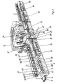
- FIG. 2 shows a system provided for the powder coating of flat sheet metal parts (2) in a structure in which individual treatment stations are further developed in detail. It's just missing the loading stations arranged at the beginning of the system and the delivery station arranged at the end for the removal of the finished coated parts.
- the sheet metal parts (2) run horizontally into the pretreatment station (4) of the system by means of the transport device (3).
- the residues such as oil, grease or the like adhering to the sheet metal parts (2) are removed by means of the roller pairs (61, 62) arranged one behind the other and provided with a textile covering.
- the residues can be collected in a collecting container (27) below the rollers (61, 62), collected and then disposed of.
- the sheet metal parts (2) which have been mechanically pre-cleaned in this way then reach the pretreatment stages (28, 29, 30) of the pretreatment station (4), in which the sheet metal parts (2) use the spray devices (31) to improve washing, rinsing or adhesion serving pretreatment process are suspended
- the pretreatment stages can consist of a degreasing stage (28), a one- or multi-part rinsing stage (29) and a one- or multi-part rinsing stage (30).
- the sheet metal parts (2) are sprayed with an alkaline cleaner in the degreasing stage (28).
- the parts are rinsed with water, preferably with demineralized water, and in the rinsing stage (30) they are treated with a special rinsing solution which improves the adhesion and improves the corrosion resistance.
- Pre-treatment stages 28, 29, 30
- further pairs of rollers (63) are arranged, which preferably have a plastic or rubber covering and through which a separation or completion of the treatment stages is achieved, so that, for. B. No carryover of baths.
- roller pairs shown in the system are designed as individual structural units which are partially enclosed by a housing and which are arranged in the system in a removable manner upwards by means of a lifting device (not shown here). This makes possible maintenance or repair easier.
- the spray devices (31) of the pretreatment station (4) are designed in the manner of a nozzle set arranged on a plate, it being possible for the individual nozzles to be pivotably mounted in the plate.
- the spray devices (31) are connected to the liquid supply via flexible feed lines and are pivotally mounted in the system so that they can be folded up or down.
- the partition walls which may be necessary can be designed in such a way that their position can preferably be shifted upwards so that the accessibility of the individual parts is further improved. For maintenance and repair work, quick interchangeability of the individual parts and better accessibility for repair and cleaning are guaranteed.
- the pre-treated sheet metal part is mechanically pre-dried with a pair of textile rollers (64) before it then goes into the actual drying station (9). runs in, at the beginning of which another pair of textile rollers (65) again provides mechanical predrying.
- the textile rollers (65) can preferably be heated.
- Air nozzle devices (32) are arranged in the drying station (9) so that the sheet metal parts (2) are subjected to convection drying with warm air.
- the air nozzles arranged on a support plate are arranged to be pivotable and adjustable.
- the sheet metal parts (2) then reach the cooling station (13), where air nozzle devices (33) with cold air supplied also cool the sheet metal parts.
- the air nozzle devices (32, 33), like the spray devices (31), are arranged in the system so as to be pivotable in order to make maintenance easier.
- a centering and straightening device (not shown in more detail) is provided in the cooling station (13), by means of which the sheet metal parts are precisely fixed in position before they are conveyed into the powder coating station (15).
- the powder coating station (15) has three stages connected in series, the coating station (25) for the actual surface coating of the parts, the intermediate station (26) and a coating station (21), in which a powder application serving as a sliding aid is carried out.
- the coating station intended only for the application of the sliding aid can have a simple structure.
- four spray guns (22) are provided under the transport device (3), which are arranged such that the coated sheet metal parts (2) can be provided on the back with a powder application.
- the transport device should be designed so that the rear of the sheet metal parts (2) are freely accessible for the spray jet of the spray guns (22).
- this powder application only serves as a sliding aid for the subsequent shaping process, a powder layer with a small layer thickness, a powder layer that does not cover the entire surface, or even a powder application that is applied in a punctiform or strip-like manner is sufficient. Even a hint of powder can be enough to get the desired sliding effect in the tool. This can be done by one or, as shown, several spray guns that may only be switched on for a short time.
- the coating stations (21, 25) are equipped with retractable changing booths so that a quick and automatic change can be made.
- the coating station (25) is connected to the air circuit of the powder coating system via the fixed intermediate station (26).
- the intermediate station (26) creates a separation from the sliding aid coating station (21).
- the intermediate station (26) has flexible air line connections (34), so that a separable and connectable connection can be created to the coating station (25).
- the transport device (35) within the coating station (25) is designed in the manner of a belt conveyor.
- the conveyor belt on which the sheet metal parts are transported is formed over the entire surface from electrically conductive material and establishes the electrical connection to the sheet metal part and to earth in the coating operation.
- This special design ensures safe and permanent grounding during powder coating. Slip contacts to the sheet metal part, which are susceptible to faults, are avoided, and no undesired capacitor charging can occur.
- a cleaning device (36) for the conveyor belt is provided in the coating station (25), through which the powder residues which form during the application can be removed from the conveyor belt.
- the sheet metal parts are coated using a gun set (38) which is arranged in the coating station (25) and consists of a plurality of powder guns.
- the entire gun set (38) essentially consists of two gun support devices (40, 41).
- the gun support device (40) located at the beginning of the coating zone is stationary and has an exterior lateral area a powder gun (39).
- the adjustability of these two pistols is indicated by the dashed representation of further positions of the powder pistols. This allows you to change the distance between these guns to match the width of the sheet to be coated.
- the guns (39) of the carrying device (40) are aimed at the edge region of the sheet metal part (2) during the coating process.
- the gun carrying device (41) has six powder guns (39), three powder guns each being mounted on a carriage (42, 43). These carriages (42, 43) are in turn connected together with a support device (44) which is arranged pivotably about an axis. The distance between the carriages (42, 43) can be adjusted.
- the carriage (42) can be adjusted laterally to the direction of transport.
- the arrangement is preferably chosen such that, as shown in FIG. 2, the two groups of pistols are offset from one another, as a result of which a good coverage of the spray pattern on the sheet is achieved.
- the carriages (42, 43) can be brought into an oscillating movement by means of a drive in a laterally reciprocating movement, preferably in one as indicated by the arrow (45).
- This design of the gun set (38) in the coating station (25) ensures a uniform coating of the sheet metal parts to be treated. Furthermore, a simple possibility is obtained to adjust the gun arrangement to different shapes and dimensions of the sheet metal parts.
- the sheet metal parts reach the coating station (21) for the sliding aid application via the intermediate station (26).
- the transport device (3) in the coating station (21) for the sliding aid coating contains special transport and support shafts (48) designed according to FIG. Knife edges (49) formed in a special manner ensure that the sheet metal parts to be transported are supported in a small area so that the sheet metal parts can be acted upon as large as possible by the powder guns arranged underneath for the sliding aid coating.
- the coated sheet metal parts pass through the lock station (17) into the drying station (18) and then into the cooling station (19).
- the cooling station (19) is then followed by a control station (46) in front of the delivery station, in which the coating quality of the sheet metal parts is checked by means of a suitable sensor scan. Appropriate feedback is sent to the central control station (47), from which the coating process can then be corrected or regulated.
- the drying or cooling stations similar to the changing booths in the powder coating stations, can be designed to be removable from the system. This creates a free space in the line of the system from which you can access the neighboring stations. Or you can move devices from the neighboring stations in the direction of flow out of the system.
- the feed station for the sheet metal parts provided at the beginning of the system be designed as a buffer with several storage locations, the parts located on the pallets being conveyed in cycles and automatically until the individual sheet metal task in the buffer.
- the delivery station can preferably be designed such that it has stack removal places for the usable sheet metal parts on both sides of the transport device, which can be loaded alternately.
- an additional stack removal station can be provided in the transport direction, to which reject parts can be fed.
- a sheet metal coil with lightly oiled and / or pre-treated in the sense of corrosion protection or adhesion mediation is supplied by the steel mill as the starting material.
- the sheet metal can still be oiled in the equipment factory.
- the sheet metal strip unwound from the sheet coil is cut into corresponding sheet metal parts in a press device.
- These flat sheet metal blanks are fed in batches to the powder coating system described above, treated in this as described above and then removed in batches from the delivery station. Only then are the fully coated sheet metal blanks formed into finished parts in appropriately designed molds.
Landscapes
- Application Of Or Painting With Fluid Materials (AREA)
- Spray Control Apparatus (AREA)
- Laminated Bodies (AREA)
- Fertilizers (AREA)
- Pretreatment Of Seeds And Plants (AREA)
Applications Claiming Priority (6)
| Application Number | Priority Date | Filing Date | Title |
|---|---|---|---|
| DE3917693 | 1989-05-31 | ||
| DE3917693 | 1989-05-31 | ||
| DE3942978 | 1989-12-23 | ||
| DE3942978 | 1989-12-23 | ||
| DE4013691 | 1990-04-28 | ||
| DE4013691 | 1990-04-28 |
Publications (3)
| Publication Number | Publication Date |
|---|---|
| EP0405164A2 true EP0405164A2 (fr) | 1991-01-02 |
| EP0405164A3 EP0405164A3 (en) | 1992-01-08 |
| EP0405164B1 EP0405164B1 (fr) | 1995-12-13 |
Family
ID=27199645
Family Applications (1)
| Application Number | Title | Priority Date | Filing Date |
|---|---|---|---|
| EP90110253A Expired - Lifetime EP0405164B1 (fr) | 1989-05-31 | 1990-05-30 | Installation et procédé de fabrication de pièces plates revêtues, en particulier, de tÔles plates |
Country Status (4)
| Country | Link |
|---|---|
| EP (1) | EP0405164B1 (fr) |
| AT (1) | ATE131420T1 (fr) |
| DE (1) | DE59009959D1 (fr) |
| ES (1) | ES2103713T3 (fr) |
Cited By (7)
| Publication number | Priority date | Publication date | Assignee | Title |
|---|---|---|---|---|
| EP0646418A1 (fr) * | 1993-10-05 | 1995-04-05 | Ykk Corporation | Système de revêtement entièrement automatique pour revêtir différents types d'objets produits en faibles quantités |
| NL1004163C2 (nl) * | 1996-10-01 | 1998-04-10 | Vms Holding Ag | Poederspuitinrichting. |
| EP0951946A2 (fr) | 1998-03-09 | 1999-10-27 | Daniel Seiler | Tunnel de revêtement pour le revêtement par poudrage de pièces plates |
| US6833031B2 (en) * | 2000-03-21 | 2004-12-21 | Wavezero, Inc. | Method and device for coating a substrate |
| WO2008040546A3 (fr) * | 2006-10-04 | 2008-09-18 | Singulus Technologies Ag | Système de traitement de surfaces et dispositif de vernissage utilisable dans celui-ci |
| CN118904589A (zh) * | 2024-10-08 | 2024-11-08 | 如东瑞格新材料有限公司 | 一种幕墙板材生产用刷涂漆生产线 |
| CN118950357A (zh) * | 2024-10-18 | 2024-11-15 | 徐州宇隆重型科技有限公司 | 一种钢结构表面喷涂设备 |
Families Citing this family (3)
| Publication number | Priority date | Publication date | Assignee | Title |
|---|---|---|---|---|
| DE69425023T2 (de) * | 1993-05-07 | 2001-02-22 | Nordson Corp., Westlake | Pulverbeschichtungssystem und Pulverbeschichtungsdicke-Sensor |
| EP0858841A3 (fr) | 1996-12-23 | 1999-03-10 | Daniel Seiler | Unité de revêtement par poudre, bande transporteuse pour une telle unité et installation munie de cette unité |
| GB2346572B (en) * | 1999-01-27 | 2003-08-20 | Gordon Laurence Banner | Powder coating process for structures |
Family Cites Families (2)
| Publication number | Priority date | Publication date | Assignee | Title |
|---|---|---|---|---|
| DE3517553A1 (de) * | 1985-05-15 | 1986-11-20 | Lichtenberg & Co Chemische Fabrik Zweigniederlassung der UK-Mineralölwerke Wenzel & Weidmann GmbH, 5180 Eschweiler | Verfahren zum beschichten fester koerper mit schmiermitteln |
| US4584859A (en) * | 1985-08-23 | 1986-04-29 | Weirton Steel Corporation | In-line control during draw-redraw of one-piece sheet metal can bodies |
-
1990
- 1990-05-30 DE DE59009959T patent/DE59009959D1/de not_active Expired - Fee Related
- 1990-05-30 EP EP90110253A patent/EP0405164B1/fr not_active Expired - Lifetime
- 1990-05-30 ES ES90110253T patent/ES2103713T3/es not_active Expired - Lifetime
- 1990-05-30 AT AT90110253T patent/ATE131420T1/de not_active IP Right Cessation
Cited By (7)
| Publication number | Priority date | Publication date | Assignee | Title |
|---|---|---|---|---|
| EP0646418A1 (fr) * | 1993-10-05 | 1995-04-05 | Ykk Corporation | Système de revêtement entièrement automatique pour revêtir différents types d'objets produits en faibles quantités |
| NL1004163C2 (nl) * | 1996-10-01 | 1998-04-10 | Vms Holding Ag | Poederspuitinrichting. |
| EP0951946A2 (fr) | 1998-03-09 | 1999-10-27 | Daniel Seiler | Tunnel de revêtement pour le revêtement par poudrage de pièces plates |
| US6833031B2 (en) * | 2000-03-21 | 2004-12-21 | Wavezero, Inc. | Method and device for coating a substrate |
| WO2008040546A3 (fr) * | 2006-10-04 | 2008-09-18 | Singulus Technologies Ag | Système de traitement de surfaces et dispositif de vernissage utilisable dans celui-ci |
| CN118904589A (zh) * | 2024-10-08 | 2024-11-08 | 如东瑞格新材料有限公司 | 一种幕墙板材生产用刷涂漆生产线 |
| CN118950357A (zh) * | 2024-10-18 | 2024-11-15 | 徐州宇隆重型科技有限公司 | 一种钢结构表面喷涂设备 |
Also Published As
| Publication number | Publication date |
|---|---|
| EP0405164B1 (fr) | 1995-12-13 |
| ES2103713T3 (es) | 1997-10-01 |
| EP0405164A3 (en) | 1992-01-08 |
| DE59009959D1 (de) | 1996-01-25 |
| ATE131420T1 (de) | 1995-12-15 |
Similar Documents
| Publication | Publication Date | Title |
|---|---|---|
| EP3459642B1 (fr) | Installation de revêtement par poudre destinée à recouvrir une pièce à usiner par poudre de revêtement | |
| DE2444209A1 (de) | Behaelterkoerper aus metall mit einem ueberzug sowie system zum waschen und ueberziehen desselben | |
| WO2011154141A1 (fr) | Installation de mise en peinture pour le revêtement/la mise en peinture d'une pièce allongée | |
| EP0405164B1 (fr) | Installation et procédé de fabrication de pièces plates revêtues, en particulier, de tÔles plates | |
| EP0777534B1 (fr) | Dispositif de mise en peinture de pieces par pulverisation | |
| DE3149588A1 (de) | Verfahren und vorrichtung zum auftragen einer beschichtung auf duenne, steife platten mittels auftragswalzen | |
| EP4132727B1 (fr) | Cabine d'application de revêtement conçue pour revêtir des jantes de véhicule | |
| WO2013186281A2 (fr) | Dispositif de revêtement | |
| DE4017361A1 (de) | Anlage und verfahren zur herstellung von pulverbeschichteten, flachen teilen, insbesondere flachen blechteilen | |
| DE69120115T2 (de) | Verfahren und Vorrichtung zur Dampfreinigung von laminierten Gegenständen | |
| DE4032719A1 (de) | Einrichtung zum auftragen von produkten, wie farben oder lacke, mit hilfe von spritzpistolen auf unregelmaessig geformte teile | |
| EP2072145A1 (fr) | Installation pour faire des revêtements | |
| DE2308132A1 (de) | Anlage zum herstellen von dosen aus metall | |
| DE19945291A1 (de) | Lackieranlage zum Lackieren von Kunststoff-Gegenständen | |
| EP0114252A1 (fr) | Installation de peinture par pulvérisation électrostatique | |
| EP3717197A1 (fr) | Installation pour la production de pièces en matière plastique revêtues et procédé associé | |
| WO2008040546A2 (fr) | Système de traitement de surfaces et dispositif de vernissage utilisable dans celui-ci | |
| DE4333859C2 (de) | Verfahren zum Lackieren der Innenflächen von Weißblechbehältnissen und Anlage zur Durchführung des Verfahrens | |
| EP0369478B1 (fr) | Enceinte pour les différents postes de traitement d'objets lors de leur revêtement électrostatique par de la poudre | |
| DE102005011812B4 (de) | Lackieranlage für Fahrzeugkarosserien in der Großserienproduktion | |
| EP0369483A1 (fr) | Installation pour revêtir des objets longs | |
| EP1702686B1 (fr) | Installation d'application de peinture en série pour une carosserie de véhicule | |
| DE102007061498B3 (de) | Verfahren und Vorrichtung zum Pulverbeschichten von Holzsubstraten | |
| DE202009018944U1 (de) | Anlage für die Innenlackierung von Metallbehältern | |
| EP2072154A2 (fr) | Procédé et dispositif de nettoyage de pièces à usiner |
Legal Events
| Date | Code | Title | Description |
|---|---|---|---|
| PUAI | Public reference made under article 153(3) epc to a published international application that has entered the european phase |
Free format text: ORIGINAL CODE: 0009012 |
|
| AK | Designated contracting states |
Kind code of ref document: A2 Designated state(s): AT BE CH DE DK ES FR GB GR IT LI LU NL SE |
|
| RBV | Designated contracting states (corrected) |
Designated state(s): AT CH DE ES FR GB GR IT LI NL SE |
|
| PUAL | Search report despatched |
Free format text: ORIGINAL CODE: 0009013 |
|
| AK | Designated contracting states |
Kind code of ref document: A3 Designated state(s): AT BE CH DE DK ES FR GB GR IT LI LU NL SE |
|
| 17P | Request for examination filed |
Effective date: 19920520 |
|
| 17Q | First examination report despatched |
Effective date: 19921030 |
|
| RAP1 | Party data changed (applicant data changed or rights of an application transferred) |
Owner name: MIELE & CIE. GMBH & CO. Owner name: SFB SPEZIALFILTER UND ANLAGENBAU AG |
|
| GRAA | (expected) grant |
Free format text: ORIGINAL CODE: 0009210 |
|
| AK | Designated contracting states |
Kind code of ref document: B1 Designated state(s): AT CH DE ES FR GB GR IT LI NL SE |
|
| PG25 | Lapsed in a contracting state [announced via postgrant information from national office to epo] |
Ref country code: NL Free format text: LAPSE BECAUSE OF FAILURE TO SUBMIT A TRANSLATION OF THE DESCRIPTION OR TO PAY THE FEE WITHIN THE PRESCRIBED TIME-LIMIT Effective date: 19951213 Ref country code: GR Free format text: LAPSE BECAUSE OF FAILURE TO SUBMIT A TRANSLATION OF THE DESCRIPTION OR TO PAY THE FEE WITHIN THE PRESCRIBED TIME-LIMIT Effective date: 19951213 |
|
| REF | Corresponds to: |
Ref document number: 131420 Country of ref document: AT Date of ref document: 19951215 Kind code of ref document: T |
|
| REF | Corresponds to: |
Ref document number: 59009959 Country of ref document: DE Date of ref document: 19960125 |
|
| ET | Fr: translation filed | ||
| REG | Reference to a national code |
Ref country code: ES Ref legal event code: BA2A |
|
| ITF | It: translation for a ep patent filed | ||
| GBT | Gb: translation of ep patent filed (gb section 77(6)(a)/1977) |
Effective date: 19960306 |
|
| PG25 | Lapsed in a contracting state [announced via postgrant information from national office to epo] |
Ref country code: AT Effective date: 19960530 |
|
| PG25 | Lapsed in a contracting state [announced via postgrant information from national office to epo] |
Ref country code: LI Effective date: 19960531 Ref country code: CH Effective date: 19960531 |
|
| NLV1 | Nl: lapsed or annulled due to failure to fulfill the requirements of art. 29p and 29m of the patents act | ||
| PLAV | Examination of admissibility of opposition |
Free format text: ORIGINAL CODE: EPIDOS OPEX |
|
| PLBQ | Unpublished change to opponent data |
Free format text: ORIGINAL CODE: EPIDOS OPPO |
|
| PLBI | Opposition filed |
Free format text: ORIGINAL CODE: 0009260 |
|
| PLBF | Reply of patent proprietor to notice(s) of opposition |
Free format text: ORIGINAL CODE: EPIDOS OBSO |
|
| 26 | Opposition filed |
Opponent name: TEGOMETALL RUDOLF BOHNACKER Effective date: 19960913 Opponent name: TFC REGLERSYSTEM AB Effective date: 19960913 |
|
| REG | Reference to a national code |
Ref country code: CH Ref legal event code: PL |
|
| PLBF | Reply of patent proprietor to notice(s) of opposition |
Free format text: ORIGINAL CODE: EPIDOS OBSO |
|
| REG | Reference to a national code |
Ref country code: ES Ref legal event code: FA2A Effective date: 19970220 |
|
| REG | Reference to a national code |
Ref country code: ES Ref legal event code: FG2A Ref document number: 2103713 Country of ref document: ES Kind code of ref document: T3 |
|
| RDAH | Patent revoked |
Free format text: ORIGINAL CODE: EPIDOS REVO |
|
| APAC | Appeal dossier modified |
Free format text: ORIGINAL CODE: EPIDOS NOAPO |
|
| APAE | Appeal reference modified |
Free format text: ORIGINAL CODE: EPIDOS REFNO |
|
| APAC | Appeal dossier modified |
Free format text: ORIGINAL CODE: EPIDOS NOAPO |
|
| PGFP | Annual fee paid to national office [announced via postgrant information from national office to epo] |
Ref country code: SE Payment date: 19990527 Year of fee payment: 10 |
|
| PGFP | Annual fee paid to national office [announced via postgrant information from national office to epo] |
Ref country code: GB Payment date: 20000425 Year of fee payment: 11 |
|
| PGFP | Annual fee paid to national office [announced via postgrant information from national office to epo] |
Ref country code: ES Payment date: 20000511 Year of fee payment: 11 |
|
| PGFP | Annual fee paid to national office [announced via postgrant information from national office to epo] |
Ref country code: FR Payment date: 20000515 Year of fee payment: 11 |
|
| PG25 | Lapsed in a contracting state [announced via postgrant information from national office to epo] |
Ref country code: SE Free format text: LAPSE BECAUSE OF NON-PAYMENT OF DUE FEES Effective date: 20000531 |
|
| EUG | Se: european patent has lapsed |
Ref document number: 90110253.3 |
|
| APAC | Appeal dossier modified |
Free format text: ORIGINAL CODE: EPIDOS NOAPO |
|
| PLBO | Opposition rejected |
Free format text: ORIGINAL CODE: EPIDOS REJO |
|
| PLBN | Opposition rejected |
Free format text: ORIGINAL CODE: 0009273 |
|
| STAA | Information on the status of an ep patent application or granted ep patent |
Free format text: STATUS: OPPOSITION REJECTED |
|
| 27O | Opposition rejected |
Effective date: 20000926 |
|
| PG25 | Lapsed in a contracting state [announced via postgrant information from national office to epo] |
Ref country code: GB Free format text: LAPSE BECAUSE OF NON-PAYMENT OF DUE FEES Effective date: 20010530 |
|
| PG25 | Lapsed in a contracting state [announced via postgrant information from national office to epo] |
Ref country code: ES Free format text: LAPSE BECAUSE OF NON-PAYMENT OF DUE FEES Effective date: 20010531 |
|
| GBPC | Gb: european patent ceased through non-payment of renewal fee |
Effective date: 20010530 |
|
| PG25 | Lapsed in a contracting state [announced via postgrant information from national office to epo] |
Ref country code: FR Free format text: LAPSE BECAUSE OF NON-PAYMENT OF DUE FEES Effective date: 20020131 |
|
| PGFP | Annual fee paid to national office [announced via postgrant information from national office to epo] |
Ref country code: DE Payment date: 20020715 Year of fee payment: 13 |
|
| REG | Reference to a national code |
Ref country code: ES Ref legal event code: FD2A Effective date: 20030303 |
|
| PG25 | Lapsed in a contracting state [announced via postgrant information from national office to epo] |
Ref country code: DE Free format text: LAPSE BECAUSE OF NON-PAYMENT OF DUE FEES Effective date: 20031202 |
|
| PG25 | Lapsed in a contracting state [announced via postgrant information from national office to epo] |
Ref country code: IT Free format text: LAPSE BECAUSE OF NON-PAYMENT OF DUE FEES Effective date: 20050530 |
|
| APAH | Appeal reference modified |
Free format text: ORIGINAL CODE: EPIDOSCREFNO |