EP0405165A2 - Mobiles Steuergehäuse - Google Patents
Mobiles Steuergehäuse Download PDFInfo
- Publication number
- EP0405165A2 EP0405165A2 EP90110277A EP90110277A EP0405165A2 EP 0405165 A2 EP0405165 A2 EP 0405165A2 EP 90110277 A EP90110277 A EP 90110277A EP 90110277 A EP90110277 A EP 90110277A EP 0405165 A2 EP0405165 A2 EP 0405165A2
- Authority
- EP
- European Patent Office
- Prior art keywords
- cap
- side profiles
- caps
- control housing
- housing according
- Prior art date
- Legal status (The legal status is an assumption and is not a legal conclusion. Google has not performed a legal analysis and makes no representation as to the accuracy of the status listed.)
- Granted
Links
Images


Classifications
-
- H—ELECTRICITY
- H05—ELECTRIC TECHNIQUES NOT OTHERWISE PROVIDED FOR
- H05K—PRINTED CIRCUITS; CASINGS OR CONSTRUCTIONAL DETAILS OF ELECTRIC APPARATUS; MANUFACTURE OF ASSEMBLAGES OF ELECTRICAL COMPONENTS
- H05K5/00—Casings, cabinets or drawers for electric apparatus
- H05K5/10—Casings, cabinets or drawers for electric apparatus comprising several parts forming a closed casing
- H05K5/13—Casings, cabinets or drawers for electric apparatus comprising several parts forming a closed casing assembled by screws
-
- H—ELECTRICITY
- H05—ELECTRIC TECHNIQUES NOT OTHERWISE PROVIDED FOR
- H05K—PRINTED CIRCUITS; CASINGS OR CONSTRUCTIONAL DETAILS OF ELECTRIC APPARATUS; MANUFACTURE OF ASSEMBLAGES OF ELECTRICAL COMPONENTS
- H05K5/00—Casings, cabinets or drawers for electric apparatus
- H05K5/06—Hermetically-sealed casings
Definitions
- the invention relates to a mobile control housing with mechanical and / or electronic control components.
- the mobile control housings previously on the market are designed as single-button housings or multi-button housings or are equipped with membrane keypads and always have certain sizes, which however no longer meet today's requirements.
- DE-GM 89 05 589 discloses a protective cover for remote controls, which is a one-piece protective housing for the shock and impact protection function of the remote control incorporated therein.
- the object of the invention is to provide a mobile control housing from a few different individual parts, which can be executed in different flat sizes due to the special design of its individual parts and allows easy installation and removal of the control components and securely encapsulates the components.
- the mobile control housing according to the invention has inner and outer side profiles which are designed as extruded profiles, as a result of which the housing can advantageously be produced in any desired length, the flat design being retained.
- the inner and outer side profile can be used on the left as well as on the right, so that only one profile type is required for both side profiles.
- cap only one type of cap is required for the two inner caps and the break-out cable feed-through is arranged out of the center, so that by turning the cap the feed can take place on the left as well as on the right side of the control housing.
- a stamped rubber seal is arranged in the joint between the inner side profiles and the inner cap, and a circumferential seal runs between the inner side profiles and the inner caps under the front plate or the rear wall, so that the control components are encapsulated in the control housing.
- the caps can be installed and removed in a simple and convenient manner by loosening an outer and an inner cap and then providing access to the interior of the housing.
- This mobile control housing is suitable for mechanical installations, e.g. B. button (crane control housing) as well as for electronic installations, eg. B. membrane keyboards and displays (programming housing).
- This control housing shows a handy design and can be held with one hand due to its low weight, so that the other hand is free to use.
- the mobile control housing consists of two inner side profiles (1), two outer side profiles (2), two inner caps (3), two outer caps (4), a front plate and a rear wall (5) and four seals (6).
- the two inner side profiles (1) accommodate electronic control parts (not shown) between them, and the inner cap (3) engages with a plug connection at the two longitudinal ends of these inner side profiles (1).
- a front plate and a rear wall (5) are fastened to the two inner side profiles (1) by screws.
- the two inner caps (3) and the length ends of the front plate (5) and the rear wall (5) are covered by the two outer caps (4).
- an outer side profile (2) which covers an inner side profile (1) and the longitudinal edge areas of the front plate (5) and rear wall (5).
- the seal (6) is arranged in each case and each extends between the front plate or rear wall (5) and the inner side profiles (1) and the inner caps (3) a circumferential seal (7).
- the inner and outer side profiles (1, 2) are each formed from extruded plastic profiles.
- the two inner and the two outer side profiles (1, 2) are identical in cross section and are only arranged in mirror image.
- the two inner caps (3) and the two outer caps (4) and the seals (6) are each constructed identically, which also applies to the front plate and the rear wall (5), so that only for the fourteen individual parts of the control housing six item types are required.
- the inner side profile (1) shows a U-shaped cross section with two U-legs of different lengths (1a, 1b) (cf. FIGS. 3 and 9).
- a continuous, undercut channel (8) with a preferably angular, such as rectangular or square cross-section is formed on the outside in connection with the U-web (1c), which extends over the entire Length of the inner side profile (1) extends and serves for the plug connection with the inner cap (3).
- a screw channel (9) for the fastening screws of the inner cap (3) is provided in each U-leg (1a, 1b) and on the outside of each U-leg (1a, 1b) is spaced apart from the channel (8) a groove (10) for the seal (7) which runs over the entire length of the profile.
- the longer U-leg (1b) shows a channel (11) which is open on the inside and undercut in cross-section for fastening the electronic control parts, which can also be used between the two U-legs (1a, 1b).
- the seal (6) is formed by a stamped rubber seal and corresponds in cross section approximately to the cross section of the inner side profile (1) in that it is provided as a rectangular plate with an extension (6a) which is adapted to the longer U-leg (1b) ( see Fig. 15).
- the inner cap (3) shows a rectangular basic shape with a flat cap wall (3a) which lies against the front ends of the inner side profiles (1) and which represents the inner side of the cap (3).
- the cap (3) is box-shaped towards the outside and shows a break-out cable duct (16) in one end region.
- the cap (3) has several, preferably four, push-through holes (17) for fastening to the two inner side profiles (1) by inserting the fastening screws through these holes (17) and the holes (14) in the seals (6) and in the screw channels (9) are screwed in.
- a groove (20) is cut out on both long sides, which takes up a large part of the cap length and runs out at a distance in front of the plug pin (15) in an arc (20a), this arc (20a) with the Grooves (10, 13) of the inner side profiles (1) and the seals (6) meet so that a circumferential over the entire length of the inner side profiles (1) and then across the side profiles (1) via the inner caps (3) , rectangular in plan view and through the arc (20a) has a rounded insertion channel for the circumferential seal (7) between the front plate (5) or rear wall (5) and inner side profiles (1) and inner caps (3).
- the outer cap (4) according to FIGS. 2, 5 to 8 shows a straight longitudinal edge (4a) on one long side and a trough-shaped longitudinal edge (4b) on the opposite long side and has two lateral, C-shaped, in the outer side profiles (2) engaging collar (4c). These collars (4c) end on the straight longitudinal edge (4a) in an internal step (4d) with which the outer cap (4) covers a longitudinal edge of the inner cap (3) and the front edge of the front plate or rear wall (5) .
- the recessed longitudinal edge (4b) forms with its C-arm and the C-arm (2a, 2b) of the outer side profiles (2) a circumferential protective collar (25) for the recessed front panel (5) or recessed rear wall (5) .
- two push-through holes (19) are provided in the outer cap (4) for the fastening screws for fixing the outer cap (4) to the inner cap (3).
- the outer side profile (2) according to FIGS. 3 and 14 shows a C-shaped cross section with a gripping surface (21) profiled on the outside and has a stop web (22) on the inside on a C-arm (2a) with which the outer side profile (2 ) on the web (1c) of the inner side profiles (1).
- the two C-arms (2a, 2b) of the outer side profile (2) are different in terms of the arc length, whereby this C-cross section is also present in the two side areas of the outer cap (4), so that the outer side profile (2) is flush with the outer cap (4) in the joint area.
- the front plate (5) and the rear wall (5) are formed by rectangular plates, the width of which corresponds to the length of the inner cap (3) and which extend over the entire length of the control device between the two outer caps (4).
- screw receptacles (24) on the inside of the outer side profiles (2), with which they can be additionally fastened by means of corresponding counterparts molded onto the inner cap (3), cf. dash-dotted representation in FIG. 3
Landscapes
- Engineering & Computer Science (AREA)
- Microelectronics & Electronic Packaging (AREA)
- Casings For Electric Apparatus (AREA)
- Mobile Radio Communication Systems (AREA)
- Switches With Compound Operations (AREA)
- Contacts (AREA)
- Fluid-Driven Valves (AREA)
Abstract
zwei an den beiden Längenenden der inneren Seitenprofile (1) unter Steckverbindung angesetzten inneren Kappen (3), einer Frontplatte (5) und einer Rückwand (5), die auf den inneren Seitenprofilen (1) und den inneren Kappen (3) aufliegen und daran durch Schrauben befestigt sind, zwei äußeren, die inneren Kappen (3) und die Längenenden der Frontplatte (5) und Rückwand (5) übergreifenden Kappen (4) und zwei äußeren, zwischen den äußeren Kappen (4) liegenden und die inneren Seitenprofile (1) sowie die Längenrandbereiche der Frontplatte (5) und Rückwand (5) überfassenden Seitenprofilen (2) gebildet.
Description
- Die Erfindung bezieht sich auf ein mobiles Steuergehäuse mit mechanischen und/oder elektronischen Steuerungseinbauten.
- Die bisher auf dem Markt befindlichen mobilen Steuergehäuse sind als Eintastergehäuse oder Mehrtastergehäuse ausgeführt bzw. sind mit Folientastatur ausgerüstet und haben dabei immer bestimmte Größen, die jedoch den heutigen Ansprüchen nicht mehr gerecht werden.
- Außerdem ist der Ein- und Ausbau der mechanischen und/oder elektronischen Steuerungseinbauten umständlich.
- Aufgrund von Marktbeobachtungen hat es sich gezeigt, daß der Umfang an Einbauten von komplexen Elektroniksteuerungen und insbesondere der Einbau von Folientastaturen und Anzeigen (Displays) zunehmend an Bedeutung für Steuerungsabläufe bei hochwertigen Maschinen und Anlagen gewinnt und hierfür größere und flachere Gehäuse gewünscht werden.
- Aus der DE-AS 1 056 224 ist eine im Freien angeordnete elektrische Kabelarmatur bekannt geworden, die aus zwei zwischen sich einen Luftmantel und einen unten offenen Luftspalt zur Feuchtigkeitsisolierung der eingebrachten Verkabelungen ergebenden Einzelgehäuse nach der Art einer am Haus außen angebrachten Telefonkabel-Anschluß- und -Verzweigerdose gebildet ist.
- Weiterhin offenbart das DE-GM 89 05 589 eine Schutzhülle für Fernsteuerungen, die ein einteiliges Schutzgehäuse zur Stoß- und Schlagschutzfunktion der darin aufgenommenen Fernsteuerung darstellt.
- Beide vorgenannten bekannten Gehäuse sind für spezielle Zwecke vorgesehen und gestaltet und lassen sich nicht für die eingangs genannten Einbauten der gewünschten Steuerungs- und Tastaturarten benutzen.
- Aufgabe der Erfindung ist es, ein mobiles Steuergehäuse aus wenigen unterschiedlichen Einzelteilen zu schaffen, das aufgrund der besonderen Gestaltung seiner Einzelteile in verschiedenen flachen Größen ausführbar ist und einen einfachen Ein- und Ausbau der Steuerungseinbauten zuläßt sowie die Einbauten sicher abgekapselt aufnimmt.
- Diese Aufgabe wird erfindungsgemäß durch die kennzeichnenden Merkmale des Patentanspruches 1 gelöst, wobei noch die in den Unteransprüchen aufgeführten Gestaltungsmerkmale vorteilhafte Weiterbildungen der Aufgabenlösung darstellen.
- Das erfindungsgemäße mobile Steuergehäuse besitzt innere und äußere Seitenprofile, die als Strangpreßprofile ausgelegt sind, wodurch in vorteilhafter Weise das Gehäuse in jeder gewünschten Länge hergestellt werden kann, wobei die flache Bauweise beibehalten wird.
- Das innere und äußere Seitenprofil läßt sich sowohl links als auch rechts einsetzen, so daß für beide - Seitenprofile jeweils nur ein Profiltyp erforderlich ist.
- Ebenfalls wird für die beiden inneren Kappen nur ein Kappentyp erforderlich und die ausbrechbare Kabeldurchführung ist außer Mitte angeordnet, so daß durch Wenden der Kappe die Zuführung sowohl an der linken als auch an der rechten Seite des Steuergehäuses erfolgen kann.
- Weiterhin ist für die beiden äußeren Kappen ebenfalls nur ein Kappentyp vorhanden und in dieser äußeren Kappe kann dann entsprechend der inneren Kappe für die Kabeldurchführung ein ausbrechbares Wandungsteil angedeutet sein.
- In dem Stoß zwischen den inneren Seitenprofilen und der inneren Kappe ist jeweils eine gestanzte Gummidichtung angeordnet und zwischen den inneren Seitenprofilen und den inneren Kappen verläuft unter der Frontplatte bzw. der Rückwand eine umlaufende Dichtung, so daß die Steuerungseinbauten in dem Steuergehäuse abgekapselt untergebracht sind.
- Der Ein- und Ausbau von vorkonfektionierten Steuerungen ist in einfacher und bequemer Weise durch die Kappen möglich, indem eine äußere und eine innere Kappe gelöst wird und dann ein Zugang zum Gehäuseinnenraum geschaffen worden ist.
- Dieses mobile Steuergehäuse ist sowohl für mechanische Einbauten, z. B. Taster (Kransteuergehäuse) als auch für elektronische Einbauten, z. B. Folientastaturen und Anzeigen (Programmiergehäuse) ausgelegt.
- Dieses Steuergehäuse zeigt eine handliche Gestaltung und kann aufgrund seines geringen Gewichtes mit einer Hand gehalten werden, so daß die andere Hand zur Bedienung frei ist.
- Auf den Zeichnungen ist ein Ausführungsbeispiel der Erfindung dargestellt, welches nachfolgend näher erläutert wird. Es zeigt:
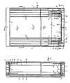
- Fig. 1 einen Längsschnitt durch ein mobiles Steuergehäuse, bestehend aus zwei inneren Seitenprofilen, zwei inneren Kappen, zwei äußeren Kappen, einer Frontplatte und einer Rückwand und zwei äußeren Seitenprofilen, gemäß Schnittlinie I-I in Fig. 2,
- Fig. 2 eine Draufsicht im teilweisen Schnitt auf dasselbe Steuergehäuse,
- Fig. 3 einen Querschnitt durch das Steuergehäuse, wobei die beiden inneren Seitenprofile, die beiden äußeren Seitenprofile und die Frontplatte und Rückwand gezeigt sind, gemäß Schnittlinie II-II in Fig. 2,
- Fig. 4 einen Querschnitt durch dasselbe Steuergehäuse gemäß Schnittlinie III-III in Fig. 2, bei dem die innere Kappe, die Frontplatte und die Rückwand und die äußere Kappe gezeigt sind,
- Fig. 5 bis 7 eine Außenansicht, eine Draufsicht und eine Innenansicht der äußeren Kappe,
- Fig. 8 einen Querschnitt durch die äußere Kappe,
- Fig. 9 einen Querschnitt durch das innere Seitenprofil,
- Fig. 10 bis 12 eine Draufsicht, eine Innenansicht und eine Außenansicht der inneren Kappe,
- Fig. 13 einen Querschnitt durch die innere Kappe,
- Fig. 14 einen Querschnitt durch das äußere Seitenprofil,
- Fig. 15 eine Vorderansicht einer Dichtung.
- Das mobile Steuergehäuse besteht aus zwei inneren Seitenprofilen (1), zwei äußeren Seitenprofilen (2), zwei inneren Kappen (3), zwei äußeren Kappen (4), einer Frontplatte und einer Rückwand (5) und vier Dichtungen (6).
- Die beiden inneren Seitenprofile (1) nehmen zwischen sich elektronische Steuerungsteile (nicht dargestellt) auf und an die beiden Längenenden dieser inneren Seitenprofile (1) legt sich jeweils die innere Kappe (3) unter Steckverbindung an.
- Auf den beiden inneren Seitenprofilen (1) ist eine Frontplatte und eine Rückwand (5) durch Schrauben befestigt. Die beiden inneren Kappen (3) und die Längenenden der Frontplatte (5) und der Rückwand (5) werden von den beiden äußeren Kappen (4) überfaßt.
- Zwischen den beiden äußeren Kappen (4) erstreckt sich über die gesamte Länge des Steuergehäuses an beiden Längsseiten jeweils ein äußeres Seitenprofil (2), welches jeweils ein inneres Seitenprofil (1) sowie die Längenrandbereiche der Frontplatte (5) und Rückwand (5) überfaßt.
- Zwischen den Stirnenden der inneren Seitenprofile (1) und den inneren Kappen (3) ist jeweils die Dichtung (6) angeordnet und zwischen Frontplatte bzw. Rückwand (5) und den inneren Seitenprofilen (1) und den inneren Kappen (3) erstreckt sich je eine umlaufende Dichtung (7).
- Die inneren und äußeren Seitenprofile (1, 2) sind jeweils von Kunststoffstrangpreßprofilen gebildet.
- Die beiden inneren und die beiden äußeren Seitenprofile (1, 2) sind im Querschnitt identisch ausgebildet und lediglich spiegelbildlich angeordnet.
- Weiterhin sind die beiden inneren Kappen (3) und die beiden äußeren Kappen (4) sowie die Dichtungen (6) jeweils gleichartig aufgebaut, was auch für die Frontplatte und die Rückwand (5) gilt, so daß für die insgesamt vierzehn Einzelteile des Steuergehäuses nur sechs Einzelteiltypen erforderlich sind.
- Das innere Seitenprofil (1) zeigt einen U-förmigen Querschnitt mit zwei unterschiedlich langen U-Schenkeln (1a, 1b) (vgl. Fig. 3 und 9).
- In den beiden U-Schenkein (1a, 1b) ist außenseitig im Anschluß an den U-Steg (1c) jeweils ein durchgehender, im Querschnitt hinterschnittener Kanal (8) mit vorzugsweise eckigem, wie rechteckigem oder quadratischem Querschnitt ausgeformt, der sich über die gesamte Länge des inneren Seitenprofiles (1) erstreckt und für die Steckverbindung mit der inneren Kappe (3) dient.
- Weiterhin ist in jedem U-Schenkel (1a, 1b) ein Schraubkanal (9) für die Befestigungsschrauben der inneren Kappe (3) vorgesehen und an der Außenseite jedes U-Schenkels (1a, 1b) liegt im Abstand neben dem Kanal (8) jeweils eine über die gesamte Profillänge verlaufende Nut (10) für die Dichtung (7).
- Außerdem zeigt der längere U-Schenkel (1b) einen innenseitig offenen, im Querschnitt hinterschnittenen Kanal (11) zur Befestigung der elektronischen Steuerteile, die auch zwischen den beiden U-Schenkeln (1a, 1b) eingesetzt werden können.
- Die Dichtung (6) ist von einer gestanzten Gummidichtung gebildet und entspricht im Querschnitt etwa dem Querschnitt des inneren Seitenprofiles (1), indem sie als Rechteckplatte mit einem Ansatz (6a) versehen ist, der dem längeren U-Schenkel (1b) angepaßt ist (vgl. Fig. 15).
- In dieser plattenförmigen Dichtung (6) sind entsprechend den Kanälen (8) zwei Durchbrüche (12) und zwei Nuten (13) für die Dichtung (7) sowie zwei Durchstecklöcher (14) für die Befestigungsschrauben der inneren Kappe (3) ausgestanzt.
- Die innere Kappe (3), gemäß Fig. 4 bis 13, zeigt eine rechteckige Grundform mit ebener, an den Stirnenden der inneren Seitenprofile (1) anliegender Kappenwandung (3a), die die innere Seite der Kappe (3) darstellt.
- An dieser ebenen Kappenwandung (3a) sind in den Eckbereichen vier Steckzapfen (15) angeformt, mit denen jede innere Kappe (3) durch die Durchbrüche (12) der Dichtungen (6) hindurch und in die Kanäle (8) des inneren Seitenprofiles (1) eingesteckt wird.
- Von der ebenen Kappenwandung (3a) aus ist die Kappe (3) nach außen hin kastenartig ausgebildet und zeigt in einem Endbereich eine ausbrechbare Kabeldurchführung (16).
- Die Kappe (3) besitzt mehrere, vorzugsweise vier, Durchstecklöcher (17) zur Befestigung an den beiden inneren Seitenprofilen (1), indem durch diese Löcher (17) und die Löcher (14) in den Dichtungen (6) die Befestigungsschrauben hindurchgesteckt und in die Schraubkanäle (9) eingeschraubt werden.
- In den beiden Längenendbereichen der inneren Kappe (3) ist auf der Breitenhalbierenden jeweils ein weiteres Durchsteckloch (18) für eine Befestigungsschraube zum Befestigen der äußeren Kappen (4) ausgenommen.
- In der inneren Kappe (3) ist an beiden Längsseiten eine Nut (20) ausgespart, die einen größten Teil der Kappenlänge einnimmt und im Abstand vor den Steckzapfen (15) in einem Bogen (20a) ausläuft, wobei dieser Bogen (20a) mit den Nuten (10, 13) der inneren Seitenprofile (1) und der Dichtungen (6) zusammentrifft, so daß über die gesamte Länge der inneren Seitenprofile (1) und dann quer zu den Seitenprofilen (1) über die inneren Kappen (3) ein umlaufender, in der Draufsicht rechteckiger und durch die Bogen (20a) eckseitig abgerundeter Einlegekanal für die umlaufende Dichtung (7) zwischen Frontplatte (5) bzw. Rückwand (5) und inneren Seitenprofilen (1) und inneren Kappen (3) geschaffen worden ist.
- Die äußere Kappe (4) gemäß Fig. 2, 5 bis 8, zeigt an einer Längsseite eine gerade Längskante (4a) und an der gegenüberliegenden Längsseite eine muldenartig eingezogene Längskante (4b) und hat zwei seitliche, C-bogenförmige, in die äußeren Seitenprofile (2) eingreifende Kragen (4c). Dabei enden diese Kragen (4c) an der geraden Längskante (4a) in einer innenseitigen Abstufung (4d), mit der die äußere Kappe (4) eine Längskante der inneren Kappe (3) und die Stirnkante der Frontplatte bzw. Rückwand (5) überfaßt.
- Die muldenartig eingezogene Längskante (4b) bildet mit ihren C-Bogen und den C-Bogen (2a, 2b) der äußeren Seitenprofile (2) einen umlaufenden Schutzkragen (25) für die vertieft liegende Frontplatte (5) oder vertieft liegende Rückwand (5).
- In der äußeren Kappe (4) sind entsprechend den Löchern (18) der inneren Kappe (3) zwei Durchstecklöcher (19) für die Befestigungsschrauben zur Festlegung der äußeren Kappe (4) an der inneren Kappe (3) vorgesehen.
- Das äußere Seitenprofil (2) gemäß Fig. 3 und 14 zeigt einen C-förmigen Querschnitt mit außenseitig profilierter Grifffläche (21) und hat innenseitig an einem C-Bogen (2a) einen Anschlagsteg (22), mit dem sich das äußere Seitenprofil (2) an den Steg (1c) der inneren Seitenprofile (1) anlegt.
Die beiden C-Bogen (2a, 2b) des äußeren Seitenprofiles (2) sind unterschiedlich in der Bogenlänge, wobei dieser C-Querschnitt auch in den beiden Seitenbereichen der äußeren Kappe (4) vorhanden ist, so daß das äußere Seitenprofil (2) mit der äußeren Kappe (4) im Stoßbereich bündig abschließt. - Die Frontplatte (5) und die Rückwand (5) sind von rechteckigen Platten gebildet, deren Breite der Länge der inneren Kappe (3) entspricht und die sich über die gesamte Steuergerätelänge zwischen den beiden äußeren Kappen (4) erstrecken.
- Die Frontplatte (5) und Rückwand (5) werden durch Schrauben auf den beiden inneren Kappen (3) befestigt, indem sie in Schraublöcher (23) der inneren Kappen (3) eingreifen.
- Dieses mobile Steuergehäuse läßt sich sowohl mit Drucktaster als auch mit Folientastatur ausrüsten.
- Die beiden äußeren Seitenprofile (2) werden durch Klemmverbindung auf der Frontplatte und Rückwand (5) sowie zwischen den angeschraubten äußeren Kappen (4) festgelegt.
- Alternativ besteht die Möglichkeit, an den äußeren Seitenprofilen (2) innenseitig Schraubaufnahmen (24) anzuformen, mit denen sie mit entsprechenden, an der inneren Kappe (3) angeformten Gegenstücken durch Schrauben zusätzlich befestigt werden können, vgl. strichpunktierte Darstellung in Fig. 3
- Die Frontplatte (5) als Bedienungsseite wird beim Einsatz von Drucktaster durch den umlaufenden Schutzkragen (25) geschützt, so daß sie vertieft im Gehäuse liegt.
- Wird eine Folientastatur eingesetzt, dann kann die Frontplatte (5) gewechselt werden und liegt dann an der ebenen Gehäuseseite dem Schutzkragen (25) gegenüber, wodurch ein leichtes Bedienen möglich ist, da die Bedienungsperson den Schutzkragen (25) nicht übergreifen muß - dieser liegt an der Gehäuse-Rückseite und überfaßt die Rückwand (5).
Claims (14)
zwei an den beiden Längenenden der inneren Seitenprofile (1) unter Steckverbindung angesetzten inneren Kappen (3),
einer Frontplatte (5) und einer Rückwand (5), die auf den inneren Seitenprofilen (1) und den inneren Kappen (3) aufliegen und daran durch Schrauben befestigt sind,
zwei äußeren, die inneren Kappen (3) und die Längenenden der Frontplatte (5) und Rückwand (5) übergreifenden Kappen (4)
und
zwei äußeren, zwischen den äußeren Kappen (4) liegenden und die inneren Seitenprofile (1) sowie die Längenrandbereiche der Frontplatte (5) und Rückwand (5) überfassenden Seitenprofilen (2)
besteht.
Applications Claiming Priority (2)
| Application Number | Priority Date | Filing Date | Title |
|---|---|---|---|
| DE3920963 | 1989-06-27 | ||
| DE3920963A DE3920963C1 (de) | 1989-06-27 | 1989-06-27 |
Publications (3)
| Publication Number | Publication Date |
|---|---|
| EP0405165A2 true EP0405165A2 (de) | 1991-01-02 |
| EP0405165A3 EP0405165A3 (en) | 1992-01-08 |
| EP0405165B1 EP0405165B1 (de) | 1996-09-18 |
Family
ID=6383642
Family Applications (1)
| Application Number | Title | Priority Date | Filing Date |
|---|---|---|---|
| EP90110277A Expired - Lifetime EP0405165B1 (de) | 1989-06-27 | 1990-05-30 | Mobiles Steuergehäuse |
Country Status (3)
| Country | Link |
|---|---|
| EP (1) | EP0405165B1 (de) |
| AT (1) | ATE143209T1 (de) |
| DE (2) | DE3920963C1 (de) |
Families Citing this family (2)
| Publication number | Priority date | Publication date | Assignee | Title |
|---|---|---|---|---|
| DE4312850A1 (de) * | 1993-04-21 | 1994-10-27 | Bopla Gehaeuse Systeme Gmbh | Gehäuse mit eingelegter Frontplatte |
| CN214676139U (zh) * | 2021-05-17 | 2021-11-09 | 浙江科雄电子科技有限公司 | 一种方便组装的实训设备用挂箱 |
Family Cites Families (6)
| Publication number | Priority date | Publication date | Assignee | Title |
|---|---|---|---|---|
| DE1056224B (de) * | 1956-05-02 | 1959-04-30 | Krone Kg | Im Freien angeordnete elektrische Kabelarmatur mit von unten heran-gefuehrten Zuleitungen oder Anschluessen, insbesondere Kabelverzweiger |
| DE2808997A1 (de) * | 1978-03-02 | 1979-09-13 | Odenwalder Kunststoffwerke | Quaderfoermiger kasten |
| DE3013489C2 (de) * | 1980-04-08 | 1983-01-05 | Siemens AG, 1000 Berlin und 8000 München | Gehäuse für elektrische Geräte |
| DE8132259U1 (de) * | 1981-11-04 | 1982-03-25 | Bündoplast GmbH, 4980 Bünde | Einbaugehäuse |
| DE8533097U1 (de) * | 1985-11-25 | 1986-04-17 | Lucas-Nülle, Rolf, 5014 Kerpen | Stromversorgungsgerät, insbesondere für Lehrzwecke |
| IT214903Z2 (it) * | 1988-11-16 | 1990-07-04 | Plass Box Srl | Custodia protettiva per telecomandi |
-
1989
- 1989-06-27 DE DE3920963A patent/DE3920963C1/de not_active Expired - Lifetime
-
1990
- 1990-05-30 EP EP90110277A patent/EP0405165B1/de not_active Expired - Lifetime
- 1990-05-30 AT AT90110277T patent/ATE143209T1/de not_active IP Right Cessation
- 1990-05-30 DE DE59010503T patent/DE59010503D1/de not_active Expired - Fee Related
Also Published As
| Publication number | Publication date |
|---|---|
| EP0405165B1 (de) | 1996-09-18 |
| DE3920963C1 (de) | 1990-12-20 |
| EP0405165A3 (en) | 1992-01-08 |
| DE59010503D1 (de) | 1996-10-24 |
| ATE143209T1 (de) | 1996-10-15 |
Similar Documents
| Publication | Publication Date | Title |
|---|---|---|
| DE69207870T2 (de) | Verbindergehäuse | |
| DE3924161C2 (de) | ||
| DE2515918A1 (de) | Mittel zur installation und zum schutz von schaltungen | |
| DE3920963C1 (de) | ||
| EP1104047B1 (de) | Klemmenanordnung für einen Niederspannungsverteiler | |
| EP3869645B1 (de) | Manipulationsschutz-abdeckung eines überspannungsschutzgeräts zur installation an einem sammelschienensystem | |
| DE4111285A1 (de) | Kabelkanal | |
| DE202016004646U1 (de) | Elektrisches Installationsgerät | |
| EP0340444B1 (de) | Gehäuse für elektrisch-elektronische Baugruppen | |
| DE4420080A1 (de) | Elektrisches Installationsgerät mit Zusatzmodul | |
| DE19835837B4 (de) | Anordnung zur Halterung und Montage von elektrischen Installationsgeräten | |
| DE3911901A1 (de) | Explosionsgeschuetzte leuchte | |
| DE3842205A1 (de) | Gehaeuse fuer den anschluss von kommunikationssystemen | |
| DE10205614B4 (de) | Anschlussadapter | |
| DE10210635B4 (de) | Explosionsgeschütztes Gehäuse mit modularem Vorsatzgehäuse | |
| EP0340700B1 (de) | Gehäuse für Reihenschaltgerät | |
| DE102005059959A1 (de) | Elektrisches Installationsgerät | |
| DE4428756C2 (de) | Positionsschalter | |
| DE2060475C3 (de) | Kabelanschluß eines explosionsgeschfitzten Gerätes | |
| DE7906878U1 (de) | Beruehrungsloser schalter | |
| DE9302630U1 (de) | Einrichtung für einen Aktor | |
| DE2532549C3 (de) | Befestigung eines Gehäuses, insbesondere für elektrische und elektronische Geräte | |
| DE3209823C2 (de) | Steckdose, insbesondere Anbausteckdose, für Rundsteckvorrichtungen | |
| DE9108297U1 (de) | Adaptertafel für elektrische Installationseinrichtungen | |
| DE3505847A1 (de) | Vielpoliger, steckbarer klemmenadapter fuer schalt- oder steuerschraenke |
Legal Events
| Date | Code | Title | Description |
|---|---|---|---|
| PUAI | Public reference made under article 153(3) epc to a published international application that has entered the european phase |
Free format text: ORIGINAL CODE: 0009012 |
|
| AK | Designated contracting states |
Kind code of ref document: A2 Designated state(s): AT BE CH DE DK ES FR GB GR IT LI LU NL SE |
|
| PUAL | Search report despatched |
Free format text: ORIGINAL CODE: 0009013 |
|
| AK | Designated contracting states |
Kind code of ref document: A3 Designated state(s): AT BE CH DE DK ES FR GB GR IT LI LU NL SE |
|
| 17P | Request for examination filed |
Effective date: 19920117 |
|
| 17Q | First examination report despatched |
Effective date: 19940719 |
|
| GRAH | Despatch of communication of intention to grant a patent |
Free format text: ORIGINAL CODE: EPIDOS IGRA |
|
| GRAA | (expected) grant |
Free format text: ORIGINAL CODE: 0009210 |
|
| GRAH | Despatch of communication of intention to grant a patent |
Free format text: ORIGINAL CODE: EPIDOS IGRA |
|
| AK | Designated contracting states |
Kind code of ref document: B1 Designated state(s): AT BE CH DE DK ES FR GB GR IT LI LU NL SE |
|
| PG25 | Lapsed in a contracting state [announced via postgrant information from national office to epo] |
Ref country code: GR Free format text: LAPSE BECAUSE OF FAILURE TO SUBMIT A TRANSLATION OF THE DESCRIPTION OR TO PAY THE FEE WITHIN THE PRESCRIBED TIME-LIMIT Effective date: 19960918 Ref country code: DK Effective date: 19960918 Ref country code: ES Free format text: THE PATENT HAS BEEN ANNULLED BY A DECISION OF A NATIONAL AUTHORITY Effective date: 19960918 |
|
| REF | Corresponds to: |
Ref document number: 143209 Country of ref document: AT Date of ref document: 19961015 Kind code of ref document: T |
|
| ITF | It: translation for a ep patent filed | ||
| ET | Fr: translation filed | ||
| GBT | Gb: translation of ep patent filed (gb section 77(6)(a)/1977) |
Effective date: 19960923 |
|
| REF | Corresponds to: |
Ref document number: 59010503 Country of ref document: DE Date of ref document: 19961024 |
|
| PGFP | Annual fee paid to national office [announced via postgrant information from national office to epo] |
Ref country code: FR Payment date: 19970421 Year of fee payment: 8 |
|
| PGFP | Annual fee paid to national office [announced via postgrant information from national office to epo] |
Ref country code: LU Payment date: 19970429 Year of fee payment: 8 |
|
| PGFP | Annual fee paid to national office [announced via postgrant information from national office to epo] |
Ref country code: NL Payment date: 19970501 Year of fee payment: 8 |
|
| PGFP | Annual fee paid to national office [announced via postgrant information from national office to epo] |
Ref country code: SE Payment date: 19970513 Year of fee payment: 8 |
|
| PGFP | Annual fee paid to national office [announced via postgrant information from national office to epo] |
Ref country code: GB Payment date: 19970516 Year of fee payment: 8 |
|
| PGFP | Annual fee paid to national office [announced via postgrant information from national office to epo] |
Ref country code: BE Payment date: 19970521 Year of fee payment: 8 |
|
| PLBE | No opposition filed within time limit |
Free format text: ORIGINAL CODE: 0009261 |
|
| STAA | Information on the status of an ep patent application or granted ep patent |
Free format text: STATUS: NO OPPOSITION FILED WITHIN TIME LIMIT |
|
| 26N | No opposition filed | ||
| PG25 | Lapsed in a contracting state [announced via postgrant information from national office to epo] |
Ref country code: GB Free format text: LAPSE BECAUSE OF NON-PAYMENT OF DUE FEES Effective date: 19980530 Ref country code: LU Free format text: LAPSE BECAUSE OF NON-PAYMENT OF DUE FEES Effective date: 19980530 |
|
| PG25 | Lapsed in a contracting state [announced via postgrant information from national office to epo] |
Ref country code: FR Free format text: LAPSE BECAUSE OF NON-PAYMENT OF DUE FEES Effective date: 19980531 Ref country code: BE Free format text: LAPSE BECAUSE OF NON-PAYMENT OF DUE FEES Effective date: 19980531 Ref country code: SE Free format text: LAPSE BECAUSE OF NON-PAYMENT OF DUE FEES Effective date: 19980531 |
|
| BERE | Be: lapsed |
Owner name: ROSE-ELEKTROTECHNIK G.M.B.H. + CO. K.G. ELEKTROTE Effective date: 19980531 |
|
| PG25 | Lapsed in a contracting state [announced via postgrant information from national office to epo] |
Ref country code: NL Free format text: LAPSE BECAUSE OF NON-PAYMENT OF DUE FEES Effective date: 19981201 |
|
| GBPC | Gb: european patent ceased through non-payment of renewal fee |
Effective date: 19980530 |
|
| EUG | Se: european patent has lapsed |
Ref document number: 90110277.2 |
|
| NLV4 | Nl: lapsed or anulled due to non-payment of the annual fee |
Effective date: 19981201 |
|
| REG | Reference to a national code |
Ref country code: FR Ref legal event code: ST |
|
| PGFP | Annual fee paid to national office [announced via postgrant information from national office to epo] |
Ref country code: CH Payment date: 20080527 Year of fee payment: 19 Ref country code: DE Payment date: 20080521 Year of fee payment: 19 |
|
| PGFP | Annual fee paid to national office [announced via postgrant information from national office to epo] |
Ref country code: AT Payment date: 20080514 Year of fee payment: 19 |
|
| PGFP | Annual fee paid to national office [announced via postgrant information from national office to epo] |
Ref country code: IT Payment date: 20080527 Year of fee payment: 19 |
|
| REG | Reference to a national code |
Ref country code: CH Ref legal event code: PL |
|
| PG25 | Lapsed in a contracting state [announced via postgrant information from national office to epo] |
Ref country code: LI Free format text: LAPSE BECAUSE OF NON-PAYMENT OF DUE FEES Effective date: 20090531 Ref country code: CH Free format text: LAPSE BECAUSE OF NON-PAYMENT OF DUE FEES Effective date: 20090531 Ref country code: AT Free format text: LAPSE BECAUSE OF NON-PAYMENT OF DUE FEES Effective date: 20090530 |
|
| PG25 | Lapsed in a contracting state [announced via postgrant information from national office to epo] |
Ref country code: DE Free format text: LAPSE BECAUSE OF NON-PAYMENT OF DUE FEES Effective date: 20091201 |
|
| PG25 | Lapsed in a contracting state [announced via postgrant information from national office to epo] |
Ref country code: IT Free format text: LAPSE BECAUSE OF NON-PAYMENT OF DUE FEES Effective date: 20090530 |