EP0405193A1 - Zum einfachen Befestigen an oder Lösen von einer Tragekonstruktion eingerichtete Beschleunigungsmesser - Google Patents
Zum einfachen Befestigen an oder Lösen von einer Tragekonstruktion eingerichtete Beschleunigungsmesser Download PDFInfo
- Publication number
- EP0405193A1 EP0405193A1 EP90110592A EP90110592A EP0405193A1 EP 0405193 A1 EP0405193 A1 EP 0405193A1 EP 90110592 A EP90110592 A EP 90110592A EP 90110592 A EP90110592 A EP 90110592A EP 0405193 A1 EP0405193 A1 EP 0405193A1
- Authority
- EP
- European Patent Office
- Prior art keywords
- shaft
- support structure
- housing structure
- accelerometer
- cylindrical portion
- Prior art date
- Legal status (The legal status is an assumption and is not a legal conclusion. Google has not performed a legal analysis and makes no representation as to the accuracy of the status listed.)
- Ceased
Links
- 230000000717 retained effect Effects 0.000 claims 3
- 241001185540 Charissa ambiguata Species 0.000 description 8
- 238000004891 communication Methods 0.000 description 3
- 238000000034 method Methods 0.000 description 3
- 238000009434 installation Methods 0.000 description 2
- 125000006850 spacer group Chemical group 0.000 description 2
- 239000004593 Epoxy Substances 0.000 description 1
- 230000001133 acceleration Effects 0.000 description 1
- 230000002411 adverse Effects 0.000 description 1
- 229910052729 chemical element Inorganic materials 0.000 description 1
- 230000004927 fusion Effects 0.000 description 1
Images

Classifications
-
- G—PHYSICS
- G01—MEASURING; TESTING
- G01P—MEASURING LINEAR OR ANGULAR SPEED, ACCELERATION, DECELERATION, OR SHOCK; INDICATING PRESENCE, ABSENCE, OR DIRECTION, OF MOVEMENT
- G01P1/00—Details of instruments
- G01P1/02—Housings
- G01P1/023—Housings for acceleration measuring devices
-
- G—PHYSICS
- G01—MEASURING; TESTING
- G01P—MEASURING LINEAR OR ANGULAR SPEED, ACCELERATION, DECELERATION, OR SHOCK; INDICATING PRESENCE, ABSENCE, OR DIRECTION, OF MOVEMENT
- G01P15/00—Measuring acceleration; Measuring deceleration; Measuring shock, i.e. sudden change of acceleration
- G01P15/02—Measuring acceleration; Measuring deceleration; Measuring shock, i.e. sudden change of acceleration by making use of inertia forces using solid seismic masses
- G01P15/08—Measuring acceleration; Measuring deceleration; Measuring shock, i.e. sudden change of acceleration by making use of inertia forces using solid seismic masses with conversion into electric or magnetic values
- G01P15/09—Measuring acceleration; Measuring deceleration; Measuring shock, i.e. sudden change of acceleration by making use of inertia forces using solid seismic masses with conversion into electric or magnetic values by piezoelectric pick-up
-
- G—PHYSICS
- G01—MEASURING; TESTING
- G01N—INVESTIGATING OR ANALYSING MATERIALS BY DETERMINING THEIR CHEMICAL OR PHYSICAL PROPERTIES
- G01N2291/00—Indexing codes associated with group G01N29/00
- G01N2291/02—Indexing codes associated with the analysed material
- G01N2291/028—Material parameters
- G01N2291/02827—Elastic parameters, strength or force
Definitions
- the present invention relates generally to accelerometers. More particularly, the invention provides accelerometers with fastening components which facilitate installation and replacement.
- Accelerometers devices used for measuring acceleration or for detecting and measuring vibration
- Accelerometers can be mounted to support structures by a variety of known methods. These methods can be more or less cumbersome depending on such application-driven factors as design specification and space limitation.
- a customer may demand accelerometers with cables which are rigidly secured to the accelerometer and not designed for removal therefrom.
- accelerometers may be mounted to the support structure with a single connector by employing a center-bolted design or a threaded stud. Securement then requires that the accelerometer be rotated along with the protruding cable as the bolt or stud is driven into a tapped bore which is formed in the support structure. This task is inherently cumbersome, and is made more so in applications which provide very limited working space.
- This invention solves the forementioned problems by providing an accelerometer that can be connected to a support structure with a single fastening component while holding the remainder of the accelerometer in a substantially fixed azimuthal position relative to the top surface of the support structure.
- the fastening component is a bolt-like member of the accelerometer that is free to rotate about a shaft which extends through the member in an axial direction. The member, however, is constrained from moving in either axial direction thereof.
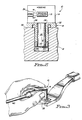
- FIG. 1 illustrates an accelerometer 10 adapted for securement to a support structure 12 (FIG. 2) in accordance with a specific embodiment of the invention.
- the support structure 12 may be the hull of a submarine, for example. However, the support structure 12 may be any structure that served as a mounting base for the accelerometer 10 in a given application.
- the accelerometer 10 comprises a housing structure 14 which contains a sensing element 15 (FIG. 2. - typically, this is a piezoelectric or piezoresistive element), a cylindrical shaft 16 that is formed integrally with the housing structure, a bolt-like member 18, and an annulet 20.
- the shaft 16 extends from the housing structure 14 to its distal end 22, and is received in an axially-extending hole 24 formed in the member 18.
- the shaft 16 is extended through the member 18 until a first end 26 of the latter abuts the bottom surface 28 of the housing structure 14.
- the shaft 16 is sufficiently long relative to the member 18 to ensure that a distal portion of the former projects beyond a second end 30 of the latter.
- the annulet is pressed onto the shaft 16 until it abuts the second end 30 of the member 18, and is fusion welded to the shaft.
- the hole 24 and shaft 16 are dimensioned such that the member 18 can be easily rotated around the shaft. There is thus provided an essentially zero-clearance fit between the first end 26 and the bottom surface 28, and between the second end 30 and the annulet 20.
- the member 16 is adapted for engagement with a torquing tool via a head 32, and is adapted for engagement with the support structure 12 (FIG. 2) via a threaded outer surface 34.
- FIG. 2 wherein the accelerometer 10 is shown assembled and extended into a tapped bore 36 formed in the support structure 12, it can be seen that if the head 32 is torqued, the member 18 will push downwardly against the annulet 20. Since the annulet 20 is rigidly secured to the shaft 16 and the latter is rigidly secured to the housing structure 14, the downward force is transferred to the housing structure and the entire accelerometer 10 is carried with the member 18. This causes the bottom surface 28 to press hard against the first end 26 of the member 18, effecting a friction lock between the member 18 and the top surface 38 of the support structure 12, and between the bottom surface 28 of the housing structure 14 and the first end 26 of the member.
- FIG. 3 illustrates the primary benefit provided by the invention.
- the housing structure 14 contains a sensing element 15.
- the housing is adapted, by any conventional means (a connector 39 and two leads 41, 43 are shown schematically) to provide for electrical communication between the internal sensing element 15 and a remote signal processing system (not shown).
- a cable, shielded wire-pair, or other conventional electrical communication channel 40 must be secured to the housing structure 14.
- the azimuthal position of the housing structure 14 relative to the top surface 38 of the support structure 12 may be held substantially fixed as illustrated, while the accelerometer 10 is connected to or disconnected from the support structure 12 by torquing the head 32 in the appropriate direction. Therefore, regardless of whether the communication channel 40 is secured to the accelerometer 10 before or after installation, the above-described problems are eliminated.
- FIG. 4 illustrates another among many possible embodiments of the invention.
- the shaft 16 (FIG. 1) is provided in the form of a cap screw 42 which is extended through the member 18 and rigidly secured to the housing structure 14 by engagement with a tapped bore 44. An epoxy is applied to the threads of the bore 44 prior to engagement.
- the head 46 of the cap screw 42 provides the function of the annulet 20 (FIG. 1).
- the shaft 16 be cylindrical along its entire length so long as a cylindrical portion is provided for the purpose of rotating the member around that portion.
- FIG. 1 Other embodiments of the invention could include the following exemplary elements which provide the functions performed in the embodiment of FIG. 1 by the annulet 20 or the bottom surface 28: 1) a boss on the shaft 16 performing the function of the bottom surface 28; 2) a washer or other spacer-type element interposed between the housing structure 14 and the member 18 and performing the function of the bottom surface 28; 3) a pin extending through a hole drilled transversely trough the shaft 16 near the distal end 22, the pin performing the function of the annulet 20; and 4) one or more bocses on the housing structure 14 performing the function of the bottom surface 28.
Landscapes
- Physics & Mathematics (AREA)
- General Physics & Mathematics (AREA)
- Connection Of Plates (AREA)
- Vibration Prevention Devices (AREA)
Applications Claiming Priority (2)
| Application Number | Priority Date | Filing Date | Title |
|---|---|---|---|
| US374403 | 1989-06-29 | ||
| US07/374,403 US4947690A (en) | 1989-06-29 | 1989-06-29 | Acceletometers adapted for efficient connection and disconnection |
Publications (1)
| Publication Number | Publication Date |
|---|---|
| EP0405193A1 true EP0405193A1 (de) | 1991-01-02 |
Family
ID=23476653
Family Applications (1)
| Application Number | Title | Priority Date | Filing Date |
|---|---|---|---|
| EP90110592A Ceased EP0405193A1 (de) | 1989-06-29 | 1990-06-05 | Zum einfachen Befestigen an oder Lösen von einer Tragekonstruktion eingerichtete Beschleunigungsmesser |
Country Status (2)
| Country | Link |
|---|---|
| US (1) | US4947690A (de) |
| EP (1) | EP0405193A1 (de) |
Families Citing this family (14)
| Publication number | Priority date | Publication date | Assignee | Title |
|---|---|---|---|---|
| US5495758A (en) * | 1993-06-17 | 1996-03-05 | Lake Shore Cryotronics, Inc. | Tachometer assembly with integral internal wrench |
| US7134334B2 (en) * | 2004-05-20 | 2006-11-14 | Analog Devices, Inc. | Integrated fastener and motion detector |
| US7500394B2 (en) * | 2005-08-19 | 2009-03-10 | Tk Holdings Inc. | Fastener integrated sensor |
| US20070169550A1 (en) * | 2006-01-26 | 2007-07-26 | Lally Robert W | Educational accelerometer |
| JP5650547B2 (ja) * | 2008-03-14 | 2015-01-07 | ラム リサーチ コーポレーションLam Research Corporation | カムロック電極クランプ |
| US8051712B2 (en) * | 2008-10-15 | 2011-11-08 | General Electric Company | Electronic stator end winding accelerometer sensor |
| EP2362946B1 (de) * | 2008-11-13 | 2015-04-01 | BAE Systems PLC | Strömungssensoren |
| US9235937B1 (en) | 2013-06-05 | 2016-01-12 | Analog Devices, Inc. | Mounting method for satellite crash sensors |
| SG10201507702RA (en) * | 2014-09-17 | 2016-04-28 | Salunda Ltd | Sensor For A Fingerboard Latch Assembly |
| CA3029116C (en) | 2016-07-05 | 2023-11-14 | Salunda Limited | Sensor for a fingerboard latch assembly |
| EP3538738B1 (de) | 2016-11-09 | 2023-06-07 | Salunda Limited | Sensor für ein drehbares element |
| USD936506S1 (en) * | 2019-06-21 | 2021-11-23 | Fatri United Testing & Control (Quanzhou) Technologies Co., Ltd. | Piezoelectric acceleration sensor |
| USD936507S1 (en) * | 2019-06-21 | 2021-11-23 | Fatri United Testing & Control (Quanzhou) Technologies Co., Ltd. | Piezoelectric acceleration sensor |
| EP3835792B1 (de) * | 2019-12-11 | 2024-06-12 | Treon Oy | Beschleunigungsaufnehmer und verfahren zur messung von beschleunigungsdaten |
Citations (3)
| Publication number | Priority date | Publication date | Assignee | Title |
|---|---|---|---|---|
| DE930764C (de) * | 1953-03-24 | 1955-07-25 | Deuta Werke Gmbh | Drehzahlabhaengiger Stromerzeuger (Geber) fuer eine Vielzahl von Anbaumoeglichkeiten |
| GB2084330A (en) * | 1980-09-22 | 1982-04-07 | Sundstrand Data Control | Protection of Accelerometers Against Impact |
| EP0321600A1 (de) * | 1987-12-22 | 1989-06-28 | Kistler Instrumente AG | Akzelerometer |
Family Cites Families (3)
| Publication number | Priority date | Publication date | Assignee | Title |
|---|---|---|---|---|
| US4347743A (en) * | 1980-09-18 | 1982-09-07 | Pile Dynamics, Inc. | Accelerometer mounting assembly |
| US4771637A (en) * | 1987-03-18 | 1988-09-20 | Kistler Instrument Corporation | Accelerometer |
| US4858470A (en) * | 1988-03-23 | 1989-08-22 | Ird Mechanalysis, Inc. | Vibration transducer mounting |
-
1989
- 1989-06-29 US US07/374,403 patent/US4947690A/en not_active Expired - Fee Related
-
1990
- 1990-06-05 EP EP90110592A patent/EP0405193A1/de not_active Ceased
Patent Citations (3)
| Publication number | Priority date | Publication date | Assignee | Title |
|---|---|---|---|---|
| DE930764C (de) * | 1953-03-24 | 1955-07-25 | Deuta Werke Gmbh | Drehzahlabhaengiger Stromerzeuger (Geber) fuer eine Vielzahl von Anbaumoeglichkeiten |
| GB2084330A (en) * | 1980-09-22 | 1982-04-07 | Sundstrand Data Control | Protection of Accelerometers Against Impact |
| EP0321600A1 (de) * | 1987-12-22 | 1989-06-28 | Kistler Instrumente AG | Akzelerometer |
Also Published As
| Publication number | Publication date |
|---|---|
| US4947690A (en) | 1990-08-14 |
Similar Documents
| Publication | Publication Date | Title |
|---|---|---|
| US4947690A (en) | Acceletometers adapted for efficient connection and disconnection | |
| US5941669A (en) | Jack-out captivated screw | |
| US6033168A (en) | Jacking screw | |
| US4858470A (en) | Vibration transducer mounting | |
| US6065743A (en) | Device for holding, positioning or clamping | |
| KR20060100239A (ko) | 차량 루프 안테나 장착용 조립체 | |
| US10808380B2 (en) | Rotator arrangement with an angle meter | |
| US20010017217A1 (en) | Measurement device having a cable probe, and a method for shortening the cable probe | |
| RU2006101976A (ru) | Соединительное устройство | |
| EP1182726A2 (de) | Auf einem Fahrzeug montierte Stabantenne | |
| EP2417306B1 (de) | Erfassungssystem, mit solch einem erfassungssystem versehenes gelenk und mit solch einem gelenksystem versehenes kraftfahrzeug | |
| USRE38882E1 (en) | Angle measuring system with a clampable shaft | |
| US6642508B2 (en) | System and method in an angle measuring system with an encoder attachment system for attaching an encoder to a motor shaft through the use of a spring generating a radial pressure | |
| US4804468A (en) | Self-retaining smooth bore insert | |
| CN200986493Y (zh) | 一种用于轴承试验机上的振动测试拾振结构 | |
| JPH10293046A (ja) | 検出器の取付構造 | |
| WO1998055773A1 (en) | Threaded fastener with over-torque protection | |
| US6332383B1 (en) | Fastening torque control tool in fastening device | |
| EP1679160B1 (de) | Vorrichtung zur einstellung eines ausgangspunkts eines industrieroboters | |
| US5144837A (en) | Acceleration detector | |
| JP2001179649A (ja) | 角度読取部品、ドライバビット組立体及びトルクドライバ | |
| CN222338743U (zh) | 一种组合式导电滑环 | |
| US6140971A (en) | Antenna device having feeding spring escape prevention ribs | |
| SE516242C2 (sv) | Mittledare för ett LC-filter, ett LC-filter medmittledare samt användning av ett LC-filter | |
| CN113784557B (zh) | 编码器防用护装置和编码器装置 |
Legal Events
| Date | Code | Title | Description |
|---|---|---|---|
| PUAI | Public reference made under article 153(3) epc to a published international application that has entered the european phase |
Free format text: ORIGINAL CODE: 0009012 |
|
| AK | Designated contracting states |
Kind code of ref document: A1 Designated state(s): CH DK FR GB LI |
|
| 17P | Request for examination filed |
Effective date: 19910625 |
|
| 17Q | First examination report despatched |
Effective date: 19920601 |
|
| STAA | Information on the status of an ep patent application or granted ep patent |
Free format text: STATUS: THE APPLICATION HAS BEEN REFUSED |
|
| 18R | Application refused |
Effective date: 19921122 |