EP0405212A2 - Maschinenlesbarer Datenträger - Google Patents
Maschinenlesbarer Datenträger Download PDFInfo
- Publication number
- EP0405212A2 EP0405212A2 EP90111001A EP90111001A EP0405212A2 EP 0405212 A2 EP0405212 A2 EP 0405212A2 EP 90111001 A EP90111001 A EP 90111001A EP 90111001 A EP90111001 A EP 90111001A EP 0405212 A2 EP0405212 A2 EP 0405212A2
- Authority
- EP
- European Patent Office
- Prior art keywords
- line
- data
- data carrier
- lines
- bar
- Prior art date
- Legal status (The legal status is an assumption and is not a legal conclusion. Google has not performed a legal analysis and makes no representation as to the accuracy of the status listed.)
- Withdrawn
Links
Images

Classifications
-
- G—PHYSICS
- G06—COMPUTING OR CALCULATING; COUNTING
- G06K—GRAPHICAL DATA READING; PRESENTATION OF DATA; RECORD CARRIERS; HANDLING RECORD CARRIERS
- G06K19/00—Record carriers for use with machines and with at least a part designed to carry digital markings
- G06K19/06—Record carriers for use with machines and with at least a part designed to carry digital markings characterised by the kind of the digital marking, e.g. shape, nature, code
- G06K19/06009—Record carriers for use with machines and with at least a part designed to carry digital markings characterised by the kind of the digital marking, e.g. shape, nature, code with optically detectable marking
- G06K19/06037—Record carriers for use with machines and with at least a part designed to carry digital markings characterised by the kind of the digital marking, e.g. shape, nature, code with optically detectable marking multi-dimensional coding
Definitions
- the invention relates to a data carrier, the data area of which is provided with parallel bar bars of different thicknesses and different distances in the form of a bar code which can be read by optical data recording devices, the data area being at least partially divided into lines, in which the line bars are arranged perpendicular to the line axis.
- the invention also relates to a method for reading such a data carrier.
- One possibility of encrypting information in a machine-readable manner is to arrange lines of different thicknesses at different distances parallel to one another according to a predetermined key on a data carrier.
- the barcode is widely used in the European article number (EAN) for the unique identification of merchandise.
- the data area is provided with such lines whose length is equal to an edge length of the rectangular data area. Since the information is contained in the width of the lines and in the width of the distances between the lines, only one dimension of the data area is used for data storage.
- code 49 is a bar code that is arranged line by line on the data area.
- the lines are arranged one below the other and completely fill the rectangular data area.
- This bar code, arranged line by line requires that the lines be read in the correct order with the data acquisition device. In the case of handheld devices, the operator must move the device line by line over the data carrier.
- the symbols are combined into words according to code 49 and provided with a parity in accordance with a predetermined key, so that a line assignment is possible on the basis of the parity pattern during decoding.
- at least one control symbol is required that, among other things, contains the number of lines.
- This arrangement of the bar code is extremely complex in terms of evaluation and does not offer the reading reliability that is required today.
- a combination of parities can be detected that simulates a certain line number.
- the information read then does not match the information content of the corresponding line, so that errors can occur when using conventional reading devices.
- each line is provided with a line indicator.
- an additional area is provided at least at one end of each line, in which the line indicator is arranged as a bar bar combination corresponding to the selected bar code.
- the total number of lines is preferably arranged in the additional area of the first line as a bar bar combination corresponding to the selected bar code.
- the additional areas are provided at both line ends.
- the additional area of the first line is one Dashed bar combination that can be read by the data acquisition device as a letter character. Since a total of up to 22 lines can be arranged one below the other, the line indicator F1 can assume values from 1 to 22.
- the assignments of the line indicators F1 to Fm are shown in the following two tables.
- Indicators of lines F2 to Fm Line assignment table for single-digit coding per line from F2 to Fm (max to F22). Signs from F2-Fm is line number Characters F2 - Fm is line number 0 2nd B 13 1 3rd C. 14 2nd 4th D 15 3rd 5 E 16 4th 6 F 17th 5 7 G 18th 6 8th H 19th 7 9 I. 20th 8th 10th J 21st 9 11 K 22 A 12
- the line indicators By arranging the line indicators both at the beginning and at the end of the line, incorrect diagonal reading is effectively prevented, since in this case the line indicator at the beginning of the reading process does not match the line indicator at the end of the reading process. The reader then discards the information.
- the line indicators also take on the function of a start and stop symbol.
- a further data field area can also be provided at the two ends of the line adjacent to the additional areas, which are occupied by a start or stop symbol as a bar bar combination corresponding to the selected bar code. In this case, it would be sufficient to provide only one line indicator per line in order to achieve optimum reading reliability.
- This data field area is preferably arranged in such a way that the line bars which represent the start or stop symbol extend at least over the entire width of all lines.
- the individual lines can be arranged in any order on the data area of the data carrier. An arrangement of the lines among each other is not absolutely necessary.
- the data carrier can be, for example, a label on which the line bars are printed in black color on a light background.
- the data carrier can be, for example, a label on which the line bars are printed in black color on a light background.
- the goods themselves can also be used as data carriers, which is useful, for example, for medicines in tablet form, since the bar code takes up little space due to the line-by-line arrangement.
- a check digit calculation using the modulo 43 method can be provided with a special weighting in order to prevent overlaps due to an inevitable offset per row field to the next.
- Two standard ModulO-43 checksums can also be staggered independently.
- the data carriers according to the invention do not require any new reading devices, but can be read with the conventional data acquisition devices.
- the light beam is guided over the data area in any order until all lines have been scanned.
- the rows are then ordered using the row indicators.
- the total number of lines contained in the additional area of the first line serves to provide the reader with the information required for this. Since, in the conventional data acquisition devices, the data carrier does not have to be positioned in a predetermined direction with respect to the reading device, a few or more lines are also read diagonally. However, this does not lead to incorrect data in the decoding, since the evaluation unit recognizes from the different line indicators at the beginning and end of the data read that this information is to be discarded.
- the laser beam is in this case, it continues over the data area, the reader possibly being able to indicate that the data carrier has to be rotated or shifted somewhat so that all lines can be scanned.
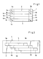
- the data carrier 1 is shown schematically in plan view in FIG. The broken bars are omitted in this illustration.
- the entire data area 2 is divided into five cells 3a to 3e.
- Each row contains 5 information in the area and has an additional area 4a, 4b, 6a and 6b at the beginning and end, in which the row indicators F1 to Fm are arranged.
- Each part indicator F is repeated identically at the end of the line.
- the additional areas 6a and 6b of the first line 3a contain the total number of lines, the selected bar-bar combination a specific one Letters according to Table 1 represents.
- the line indicator F1 contains a line combination which corresponds to the letter P. This distinguishes the total number that is encoded in F1 from the line indicator Fm in the fifth line 3e, which contains the number 5. The reading and evaluation device can thus differentiate the total number from the number of the last line.
- the line indicators F1 to Fm also take on the function of a stop and start symbol.
- a further embodiment of the data carrier 1 is shown in FIG.
- the data area 2 has rows 3a to 3c arranged in a step-like manner. However, any other arbitrary arrangement of lines within the data area of the data carrier 1 is also possible.
- FIG. 3 further data field areas 7 and 8 are provided at the beginning of each line and at the end of each line, which contain the start or stop symbol as a combination of bars.
- FIG. 4 An example can be seen in FIG. 4, where the dashed bars, which represent the start or stop symbol in the data field areas 7 and 7, extend over the entire width of all lines.
- the additional fields for the line indicators are also contained in the embodiment in FIG. 4, but can only be identified on the basis of the respective stroke combination.
Landscapes
- Physics & Mathematics (AREA)
- General Physics & Mathematics (AREA)
- Engineering & Computer Science (AREA)
- Theoretical Computer Science (AREA)
- Optical Recording Or Reproduction (AREA)
- Printers Characterized By Their Purpose (AREA)
Abstract
Description
- Die Erfindung betrifft einen Datenträger, dessen Datenfläche mit parallelen Strichbalken unterschiedlicher Dicke und unterschiedlichen Abständen in Form eines Strichcodes versehen ist, der mit optischen Datenerfassungsgeräten lesbar ist, wobei die Datenfläche zumindest teilweise in Zeilen unterteilt ist, in dem die Strichbalken senkrecht zur Zeilenachse angeordnet sind. Die Erfindung betrifft auch ein Verfahren zum Lesen eines solchen Datenträgers.
- Eine Möglichkeit, Informationen maschinenlesbar zu verschlüsseln, besteht darin, Striche unterschiedlicher Dicke in unterschiedlichen Abständen parallel zueinander nach einem vorgegebenen Schlüssel auf einem Datenträger anzuordnen. Eine breite Anwendung findet der Strichcode bei der europäischen Artikelnummer (EAN) zur eindeutigen Kennzeichnung von Handelswaren.
- Bei diesem Strichcode, der beispielsweise auf Etiketten aufgedruckt ist, ist die Datenfläche mit derartigen Strichen versehen, deren Länge gleich einer Kantenlänge der rechteckigen Datenfläche ist. Da die Information in der Breite der Striche und in der Breite der Abstände der Striche zueinander enthalten ist, wird nur eine Dimension der Datenfläche zur Datenspeicherung ausgenutzt.
- Diese Datenträger haben den Nachteil, daß die Informationsdichte äußerst gering ist. Bei Waren, die entsprechend große Flächen zur Anbringung dieses Datenträgers aufweisen, stellt der Platzbedarf kein Problem dar.
- Kein Platz ist allerdings bei hochwertigen Komponenten der Mikroelektronik vorhanden, wie z.B. auf integrierten Schaltkreisen, welche gern mit individuellen Kennungen versehen werden. Dies ist z.B. bei den sogenannten EPROMs der Fall. Auch die Leiterplatte selbst, welche im Zuge der Seriennummernvergabe vorbereitend für Qualitätskontrolle, Lagerhaltung und Garantieverfolgung mit Strichcodes versehen werden, verfügt über immer weniger Platz bei steigendem Informationsbedarf.
- Die Schmuckindustrie und der Schmuckhandel versuchen durch schwierig lesbare Ultra-High-Density-Codierung die Information in einer Achse unterzubringen. Auch hier besteht ein Bedürfnis, auf einer relativ kleinen Fläche eine Vielzahl von Daten unterzubringen. Die Medizintechnik steht im Augenblick vor dem Problem, daß zunehmend eine automatisch lesbare Beschriftung von Medikamenten verlangt wird, wofür die bisher verwendeten Datenträger mit Strichcode wegen ihres großen Platzbedarfes ungeeignet sind, da Medikamente selbst stets in kleinen Packungen untergebracht sind.
- Von der Industrie wird auch zunehmend gewünscht, Werkzeuge oder Kleinteile für die verschiedensten Einsatzgebiete mit einem entsprechenden Code zu versehen, wobei eine automatische Identifikation mit großem Informationsbedarf auf kleinstem Raum möglich sein soll.
- Von der Automobilindustrie werden bereits Warenanhänger verwendet, welche mit bis zu 40 Zeichen auf ca. sechs Zeilen die gesamte Information unterbringen. Hierbei wird allerdings nicht auf eine konsequente Platzeinsparung geachtet. Zur Lösung dieser Probleme wurde der Code 49 entwickelt, der ein Strichcode ist, der zeilenweise auf der Datenfläche angeordnet ist. Die Zeilen sind untereinander angeordnet und füllen die rechteckige Datenfläche vollständig aus. Dieser zeilenweise angeordente Strichcode macht es erforderlich, daß die Zeilen in der richtigen Reihenfolge mit dem Datenerfassungsgerät gelesen werden. Bei Handgeräten muß die Bedienungsperson das Gerät zeilenweise über den Datenträger führen.
- Wenn jedoch ein automatische Lesegerät verwendet wird, bei dem der Laserstrahl längs eines vorgegebenen Weges kreuz und quer über den Datenträger geführt wird, so daß der Datenträger in jeder beliebigen Position gelesen werden kann, werden die Zeilen nicht in ihrer richtigen Reihenfolge abgetastet, wobei eine oder mehrere Zeilen auch diagonal gelesen werden. Dies führt bei der Decodierung zu einem Datengemisch, das mit dem tatsächlichen Informationsgehalt des Datenträgers nichts mehr zu tun hat.
- Um hier eine gewisse Abhilfe zu schaffen, werden gemäß Code 49 die Symbole zu Worten zusammengefaßt und entsprechend eines vorgegebenen Schlüssels mit einer Parität versehen, so daß anhand des Paritätsmusters bei der Decodierung eine Zeilenzuordnung möglich ist. Darüberhinaus ist noch mindestens ein Kontrollsymbol erforderlich, daß u.a. die Zeilenanzahl enhält.
- Diese Anordnung des Strichcodes ist bezüglich der Auswertung äußerst aufwendig und bietet nicht die Lesesicherheit, die heutzutage gefordert wird. Beim Diagonallesen kann eine Paritätskombination erfaßt werden, die eine bestimmte Zeilennummer vortäuscht. Die gelesene Information stimmt dann aber nicht mit dem Informationsgehalt der entsprechenden Zeile überein, so daß bei Verwendung herkömmlicher Lesegeräte Fehler auftreten können.
- Es ist daher Aufgabe der Erfindung, einen Datenträger zu schaffen, bei dem der Strichcode zeilenweise angeordnet ist und der mit herkömmlichen Datenerfassungsgeräten lesbar ist, wobei die Lesesicherheit gegenüber bekannten Datenträgern deutlich verbessert ist.
- Diese Aufgabe wird mit einem Datenträger gemäß den kennzeichnenden Merkmalen von Anspruch 1 und einem Verfahren gemäß Anspruch 10 gelöst.
- Es hat sich gezeigt, daß die Lesesicherheit deutlich erhöht werden kann, wenn jede Zeile mit einem Zeilenindikator versehen ist. Zu diesem Zweck ist zumindest an einem Ende jeder Zeile eine Zusatzfläche vorgesehen, in der der Zeilenindikator als eine dem gewählten Strichcode entsprechende Strichbalkenkombination angeordnet ist.
- Vorzugsweise ist in der Zusatzfläche der ersten Zeile die Gesamtanzahl der Zeilen als dem gewählten Strichcode entsprechende Strichbalkenkombination angeordnet.
- Gemäß einer besonderen Ausführungsform sind die Zusatzflächen an beiden Zeilenenden vorgesehen.
- Damit die in der Zusatzfläche der ersten Zeile codiert enthaltene Gesamtanzahl der Zeichen nicht mit dem Zeilenindikator der letzten Zeile verwechselt werden kann, ist die Zusatzfläche der ersten Zeile mit einer Strichbalkenkombination belegt, die vom Datenerfassungsgerät als Buchstabenzeichen lesbar ist. Da insgesamt bis zu 22 Zeilen untereinander angeordnet werden können, kann der Zeilenindikator F1 Werte von 1 bis 22 annehmen. Welche Zuordnungen der Zeilenindikatoren F1 bis Fm möglich sind, sind aus den nachfolgenden beiden Tabellen zu entnehmen.
Indikator Zeile 1, F1: Folgende Tabelle zeigt die Verknüpfung von Zeilenanzahl "m" zum Zeichencode in der ersten Zeile F1. Zeichen als F1 Zeilenzahl m Zeichen als F1 Zeilenzahl m L 1 W 12 M 2 X 13 N 3 Y 14 O 4 Z 15 P 5 - 16 Q 6 . 17 R 7 18 S 8 $ 19 T 9 / 20 U 10 + 21 V 11 % 22 Indikatoren der Zeilen F2 bis Fm: Zeilenzuordnungstabelle für einstellige Codierung pro Zeile von F2 bis Fm (max bis F22). Zeichen von F2-Fm ist Zeile Nummer Zeichen F2 - Fm ist Zeile Nummer 0 2 B 13 1 3 C 14 2 4 D 15 3 5 E 16 4 6 F 17 5 7 G 18 6 8 H 19 7 9 I 20 8 10 J 21 9 11 K 22 A 12 - Durch die Anordnung der Zeilenindikatoren sowohl am Zeilenanfang als auch am Zeilenende wird ein fehlerhaftes Diagonallesen wirksam verhindert, da in diesem Fall der Zeilenindikator zu Beginn des Lesevorganges nicht mit dem Zeilenindikator am Ende des Lesevorgangs übereinstimmt. Vom Lesegerät wird daraufhin die Information verworfen. Die Zeilenindikatoren übernehmen in diesem Fall auch die Funktion eines Start- und Stopsymbols.
- Zusätzlich kann jedoch auch an den beiden Zeilenenden an den Zusatzflächen angrenzend je eine weitere Datenfeldfläche vorgesehen sein, die mit einem Start- bzw. Stopsymbol als dem gewählten Strichcode entsprechende Strichbalkenkombination belegt sein. In diesem Fall würde es zur Erzielung einer optimalen Lesesicherheit ausreichen, pro Zeile nur einen Zeilenindikator vorzusehen.
- Vorzugsweise sind diese Datenfeldfläche so angeordnet, daß sich die Strichbalken, die das Start- bzw. Stopsymbol darstellen, zumindest über die Gesamtbreite aller Zeilen erstrecken.
- Durch die Verwendung von Zusatzflächen mit Zeilenindikatoren können die einzelnen Zeilen in beliebiger Anordnung auf der Datenfläche des Datenträgers angeordnet sein. Eine Anordnung der Zeilen untereinander ist nicht zwingend erforderlich.
- Der Datenträger kann beispielsweise ein Etikett sein, auf dem die Strichbalken auf einem hellen Untergrund in schwarzer Farbe aufgedruckt sind. Es ist aber auch möglich, den Datenträger aus verformbarem Material herzustellen, wobei dann die Strichbalken oder die Zwischenräume in Form von Rillen eingeprägt oder eingraviert sind. Es kann aber auch die Ware selbst als Datenträger verwendet werden, was sich beispielsweise bei Medikamenten in Tablettenform anbietet, da der Platzbedarf durch die zeilenweise Anordnung des Strichcodes gering ist.
- Die Anordnung von Zusatzfeldern mit Zeilenindikatoren kann mit weiteren Sicherheitschecks verbunden werden. So kann beispielsweise eine Prüfziffernrechnung im Modulo-43-Verfahren mit einer besonderen Wichtung vorgesehen sein, um Überschneidungen durch einen zwangsläufigen Versatz pro Zeilenfeld zum nächsten zu verhindern. Auch können zwei Standard-ModulO-43-Checksummen unabhängig versetzt vorgesehen sein.
- Die erfindungsgemäßen Datenträger erfordern keine neuen Lesegeräte, sondern können mit den herkömmlichen Datenerfassungsgeräten gelesen werden. Hierbei wird der Lichtstrahl in beliebiger Reihenfolge solange über die Datenfläche geführt, bis alle Zeilen abgetastet sind. Anschließend werden die Zeilen anhand der Zeilenindikatoren geordnet. Die in der Zusatzfläche der ersten Zeile enthaltene Gesamtanzahl der Zeilen dient dazu, dem Lesegerät die hierfür erforderliche Information zur Verfügung zu stellen. Da bei den herkömmlichen Datenerfassungsgeräten der Datenträger bezüglich des Lesegerätes nicht in einer vorgegebenen Richtung positioniert werden muß, werden einige oder mehrere Zeilen auch diagonal gelesen. Dies führt jedoch nicht zu fehlerhaften Daten bei der Decodierung, da von der Auswerteeinheit anhand der unterschiedlichen Zeilenindikatoren am Anfang und Ende der jeweils gelesenen Daten erkannt wird, daß diese Information zu verwerfen ist. Der Laserstrahl wird in diesem Fall weiter über die Datenfläche geführt, wobei ggf. das Lesegerät anzeigen kann, daß der Datenträger etwas gedreht oder verschoben werden muß, so daß alle Zeilen abtastbar sind.
- Beispielhafte Ausführungsformen der Erfindung werden nachfolgend anhand der Zeichnungen näher erläutert.
- Es zeigen:
- Fig. 1 die schematische Darstellung eines Datenträgers in Draufsicht;
- Fig. 2 eine Draufsicht auf einen Datenträger in einer weiteren Ausführungsform;
- Fig. 3 die Draufsicht auf einen Datenträger in einer weiteren Ausführungsform und
- Fig. 4 den Datenträger mit eingezeichneten Strichbalken gemäß der in Figur 3 gezeigten Ausführungsform.
- In der Figur 1 ist der Datenträger 1 in Draufsicht schematisch dargestellt. Die Strichbalken sind in dieser Darstellung weggelassen. Die gesamte Datenfläche 2 ist in fünf Zellen 3a bis 3e unterteilt. Jede Zeile enthält in der Fläche 5 Informationen und besitzt am Anfang und Ende je eine Zusatzfläche 4a, 4b, 6a und 6b, in denen die Zeilenindikatoren F1 bis Fm angeordnet sind. Jeder Teilenindikator F wiederholt sich identisch am Zeilenende.
- Die Zusatzflächen 6a und 6b der ersten Zeile 3a enthalten die Gesamtanzahl der Zeilen, wobei die gewählte Strichbalkenkombination einen bestimmten Buchstaben gemäß der Tabelle 1 darstellt. In dem hier gezeigten Beispiel mit 5 Zeilen enthält der Zeilenindikator F1 eine Strichkombination, die dem Buchstaben P entspricht. Damit wird die Gesamtanzahl, die in F1 codiert enthalten ist, von dem Zeilenindikator Fm in der fünften Zeile 3e , der die Zahl 5 enthält, unterschieden. Das Lese- und Auswertegerät kann damit die Gesamtanzahl von der Nummer der letzten Zeile unterscheiden. In der hier gezeigten Ausführungsform der Figur 1 übernehmen die Zeilenindikatoren F1 bis Fm auch die Funktion eines Stop- und Startsymbols.
In der Figur 2 ist eine weitere Ausführungsform des Datenträgers 1 dargestellt. Die Datenfläche 2 weist treppenförmig angeordnete Zeilen 3a bis 3c auf. Es ist aber auch jede andere beliebige Anordnung von Zeilen innerhalb der Datenfläche des Datenträgers 1 möglich. - In der Figur 3 sind zu Beginn jeder Zeile und am Ende jeder Zeile weitere Datenfeldflächen 7 und 8 vorgesehen, die das Start- bzw. Stopsymbol als Strichbalkenkombination enthalten. Ein Beispiel ist in der Figur 4 zu sehen, wo die Strichbalken, die das Start- bzw. Stopsymbol in den Datenfeldflächen 7 und repräsentieren, sich über die gesamte Breite aller Zeilen erstrecken. Die Zusatzfelder für die Zeilenindikatoren sind auch in der Ausführungsform der Figur 4 enthalten, können jedoch nur anhand der jeweiligen Strichkombination identifiziert werden.
-
- 1 Datenträger
- 2 Datenfeld
- 3a bis 3e Zeilen
- 4a, 4b Zusatzfelder für Zeilenindidatoren
- 5 Fläche für Informationen
- 6a, 6b Zusatzfeld der ersten Zeile für Gesamtanzahl der Zeilen
- 7 Datenfeldfläche für Startsymbol
- 8 Datenfeldfläche für Stopymbol
Claims (11)
daß zumindest an einem Ende jeder Zeile (3) eine Zusatzfläche (4, 6) vorgesehen ist, in der ein Zeilenindikator (F) als dem gewählten Strichcode entsprechende Strichbalkenkombination angeordnet ist.
daß anschließend die Zeilen mittels der Zeilenindikatoren geordnet werden.
Applications Claiming Priority (2)
| Application Number | Priority Date | Filing Date | Title |
|---|---|---|---|
| DE19893921099 DE3921099A1 (de) | 1989-06-28 | 1989-06-28 | Maschinenlesbarer datentraeger |
| DE3921099 | 1989-06-28 |
Publications (2)
| Publication Number | Publication Date |
|---|---|
| EP0405212A2 true EP0405212A2 (de) | 1991-01-02 |
| EP0405212A3 EP0405212A3 (en) | 1992-12-02 |
Family
ID=6383726
Family Applications (1)
| Application Number | Title | Priority Date | Filing Date |
|---|---|---|---|
| EP19900111001 Withdrawn EP0405212A3 (en) | 1989-06-28 | 1990-06-11 | Machine readable data carrier |
Country Status (2)
| Country | Link |
|---|---|
| EP (1) | EP0405212A3 (de) |
| DE (1) | DE3921099A1 (de) |
Cited By (4)
| Publication number | Priority date | Publication date | Assignee | Title |
|---|---|---|---|---|
| US5202552A (en) * | 1991-04-22 | 1993-04-13 | Macmillan Bloedel Limited | Data with perimeter identification tag |
| GB2268442A (en) * | 1992-04-30 | 1994-01-12 | Sento Krei | Automatic telephone dialling card with multi-stage bar code and card printer |
| FR2715750A1 (fr) * | 1994-02-01 | 1995-08-04 | Giat Ind Sa | Dispositif code d'identification d'un objet ou d'une personne. |
| WO1996003711A1 (en) * | 1994-07-26 | 1996-02-08 | Metanetics Corporation | Packet bar code encoding and decoding |
Family Cites Families (2)
| Publication number | Priority date | Publication date | Assignee | Title |
|---|---|---|---|---|
| US4728784A (en) * | 1987-01-30 | 1988-03-01 | Federal Express Corporation | Apparatus and method of encoding and decoding barcodes |
| US4794239A (en) * | 1987-10-13 | 1988-12-27 | Intermec Corporation | Multitrack bar code and associated decoding method |
-
1989
- 1989-06-28 DE DE19893921099 patent/DE3921099A1/de not_active Withdrawn
-
1990
- 1990-06-11 EP EP19900111001 patent/EP0405212A3/de not_active Withdrawn
Cited By (4)
| Publication number | Priority date | Publication date | Assignee | Title |
|---|---|---|---|---|
| US5202552A (en) * | 1991-04-22 | 1993-04-13 | Macmillan Bloedel Limited | Data with perimeter identification tag |
| GB2268442A (en) * | 1992-04-30 | 1994-01-12 | Sento Krei | Automatic telephone dialling card with multi-stage bar code and card printer |
| FR2715750A1 (fr) * | 1994-02-01 | 1995-08-04 | Giat Ind Sa | Dispositif code d'identification d'un objet ou d'une personne. |
| WO1996003711A1 (en) * | 1994-07-26 | 1996-02-08 | Metanetics Corporation | Packet bar code encoding and decoding |
Also Published As
| Publication number | Publication date |
|---|---|
| EP0405212A3 (en) | 1992-12-02 |
| DE3921099A1 (de) | 1991-01-03 |
Similar Documents
| Publication | Publication Date | Title |
|---|---|---|
| DE2264417C3 (de) | Codemarke mit optisch abtastbaren Informationen in Form von auf einem Trägermedium befindlichen konzentrischen Ringen | |
| DE2228587C2 (de) | Anordnung zum Markieren von Belegen | |
| EP0694870A1 (de) | Verfahren zum Kennzeichnen von Gegenständen mit Code-Symbolen, optisch lesbarer Code | |
| EP0271096B1 (de) | Farbcodierung von Informationsträgern | |
| DE2400334A1 (de) | Tragbares lesegeraet | |
| DE2711413A1 (de) | Formatsteuerung fuer textautomaten | |
| DE7639778U1 (de) | Letternkoerper | |
| DE3330261A1 (de) | Verfahren zum codieren bzw. dekodieren von informationen, vorrichtung zum aufbringen der codierten information auf eine druckform bzw. zum uebertragen der information von der druckform auf einen anderen informationstraeger und die druckform selbst | |
| DE3725217C2 (de) | ||
| DE2362006A1 (de) | Vorrichtung zum abtasten von zeichen | |
| DE3520289C2 (de) | ||
| DE69318078T2 (de) | Lesevorrichtung für magnetisches Etikett | |
| DE1774690A1 (de) | Verfahren und Vorrichtung zum Aufdrucken von Codierfarben sowie zum Abfragen der Informationen | |
| EP0405212A2 (de) | Maschinenlesbarer Datenträger | |
| EP0405513B1 (de) | Gerät zur remissions-photometrischen Analyse von Flüssigkeitsproben | |
| DE2059796A1 (de) | Verfahren zur UEbertragungsaufzeichnung in von Menschen und Maschinen lesbarer Form sowie UEbertragungsvorrichtung zur Ausfuehrung dieses Verfahrens | |
| DE2513890A1 (de) | Leiterplatte mit maschinell lesbarer codierung | |
| DE2023404C3 (de) | ||
| DE2116833A1 (de) | Aufzeichnungsträger | |
| EP0098955B1 (de) | Verfahren zum Lesen von Strichcodes | |
| EP1700255B1 (de) | Display für die anzeige von programmierbaren barcodes | |
| DE3006835B1 (de) | Schrifttraeger fuer handschriftliche Zeichen | |
| DE2200775A1 (de) | Einrichtungen zur Erkennung alphanumerischer Zeichen | |
| DE2849154C2 (de) | Einrichtung zum erleichterten Auffinden von geschriebenen Textteilen an Schreib- oder Büromaschinen ähnlicher Bauart | |
| EP0102079A2 (de) | Verfahren und Anordnung zum Programmieren eines Festwert-Speichers eines digital gesteuerten Zeichengerätes |
Legal Events
| Date | Code | Title | Description |
|---|---|---|---|
| PUAI | Public reference made under article 153(3) epc to a published international application that has entered the european phase |
Free format text: ORIGINAL CODE: 0009012 |
|
| AK | Designated contracting states |
Kind code of ref document: A2 Designated state(s): AT BE CH DE ES FR GB LI LU NL SE |
|
| PUAL | Search report despatched |
Free format text: ORIGINAL CODE: 0009013 |
|
| AK | Designated contracting states |
Kind code of ref document: A3 Designated state(s): AT BE CH DE ES FR GB LI LU NL SE |
|
| 17P | Request for examination filed |
Effective date: 19930204 |
|
| 17Q | First examination report despatched |
Effective date: 19950404 |
|
| STAA | Information on the status of an ep patent application or granted ep patent |
Free format text: STATUS: THE APPLICATION IS DEEMED TO BE WITHDRAWN |
|
| 18D | Application deemed to be withdrawn |
Effective date: 19950815 |