EP0405225A2 - Informationsspeicherungsmedium - Google Patents
Informationsspeicherungsmedium Download PDFInfo
- Publication number
- EP0405225A2 EP0405225A2 EP90111119A EP90111119A EP0405225A2 EP 0405225 A2 EP0405225 A2 EP 0405225A2 EP 90111119 A EP90111119 A EP 90111119A EP 90111119 A EP90111119 A EP 90111119A EP 0405225 A2 EP0405225 A2 EP 0405225A2
- Authority
- EP
- European Patent Office
- Prior art keywords
- recording layer
- layer
- storage medium
- information storage
- protective layer
- Prior art date
- Legal status (The legal status is an assumption and is not a legal conclusion. Google has not performed a legal analysis and makes no representation as to the accuracy of the status listed.)
- Withdrawn
Links
Images




Classifications
-
- G—PHYSICS
- G11—INFORMATION STORAGE
- G11B—INFORMATION STORAGE BASED ON RELATIVE MOVEMENT BETWEEN RECORD CARRIER AND TRANSDUCER
- G11B7/00—Recording or reproducing by optical means, e.g. recording using a thermal beam of optical radiation by modifying optical properties or the physical structure, reproducing using an optical beam at lower power by sensing optical properties; Record carriers therefor
- G11B7/24—Record carriers characterised by shape, structure or physical properties, or by the selection of the material
- G11B7/241—Record carriers characterised by shape, structure or physical properties, or by the selection of the material characterised by the selection of the material
- G11B7/242—Record carriers characterised by shape, structure or physical properties, or by the selection of the material characterised by the selection of the material of recording layers
- G11B7/243—Record carriers characterised by shape, structure or physical properties, or by the selection of the material characterised by the selection of the material of recording layers comprising inorganic materials only, e.g. ablative layers
- G11B7/2433—Metals or elements of Groups 13, 14, 15 or 16 of the Periodic Table, e.g. B, Si, Ge, As, Sb, Bi, Se or Te
-
- G—PHYSICS
- G11—INFORMATION STORAGE
- G11B—INFORMATION STORAGE BASED ON RELATIVE MOVEMENT BETWEEN RECORD CARRIER AND TRANSDUCER
- G11B7/00—Recording or reproducing by optical means, e.g. recording using a thermal beam of optical radiation by modifying optical properties or the physical structure, reproducing using an optical beam at lower power by sensing optical properties; Record carriers therefor
- G11B7/004—Recording, reproducing or erasing methods; Read, write or erase circuits therefor
- G11B7/0045—Recording
- G11B7/00454—Recording involving phase-change effects
-
- G—PHYSICS
- G11—INFORMATION STORAGE
- G11B—INFORMATION STORAGE BASED ON RELATIVE MOVEMENT BETWEEN RECORD CARRIER AND TRANSDUCER
- G11B7/00—Recording or reproducing by optical means, e.g. recording using a thermal beam of optical radiation by modifying optical properties or the physical structure, reproducing using an optical beam at lower power by sensing optical properties; Record carriers therefor
- G11B7/24—Record carriers characterised by shape, structure or physical properties, or by the selection of the material
- G11B7/241—Record carriers characterised by shape, structure or physical properties, or by the selection of the material characterised by the selection of the material
- G11B7/242—Record carriers characterised by shape, structure or physical properties, or by the selection of the material characterised by the selection of the material of recording layers
- G11B7/243—Record carriers characterised by shape, structure or physical properties, or by the selection of the material characterised by the selection of the material of recording layers comprising inorganic materials only, e.g. ablative layers
-
- G—PHYSICS
- G11—INFORMATION STORAGE
- G11B—INFORMATION STORAGE BASED ON RELATIVE MOVEMENT BETWEEN RECORD CARRIER AND TRANSDUCER
- G11B7/00—Recording or reproducing by optical means, e.g. recording using a thermal beam of optical radiation by modifying optical properties or the physical structure, reproducing using an optical beam at lower power by sensing optical properties; Record carriers therefor
- G11B7/24—Record carriers characterised by shape, structure or physical properties, or by the selection of the material
- G11B7/241—Record carriers characterised by shape, structure or physical properties, or by the selection of the material characterised by the selection of the material
- G11B7/242—Record carriers characterised by shape, structure or physical properties, or by the selection of the material characterised by the selection of the material of recording layers
- G11B7/243—Record carriers characterised by shape, structure or physical properties, or by the selection of the material characterised by the selection of the material of recording layers comprising inorganic materials only, e.g. ablative layers
- G11B2007/24302—Metals or metalloids
- G11B2007/2431—Metals or metalloids group 13 elements (B, Al, Ga, In)
-
- G—PHYSICS
- G11—INFORMATION STORAGE
- G11B—INFORMATION STORAGE BASED ON RELATIVE MOVEMENT BETWEEN RECORD CARRIER AND TRANSDUCER
- G11B7/00—Recording or reproducing by optical means, e.g. recording using a thermal beam of optical radiation by modifying optical properties or the physical structure, reproducing using an optical beam at lower power by sensing optical properties; Record carriers therefor
- G11B7/24—Record carriers characterised by shape, structure or physical properties, or by the selection of the material
- G11B7/241—Record carriers characterised by shape, structure or physical properties, or by the selection of the material characterised by the selection of the material
- G11B7/242—Record carriers characterised by shape, structure or physical properties, or by the selection of the material characterised by the selection of the material of recording layers
- G11B7/243—Record carriers characterised by shape, structure or physical properties, or by the selection of the material characterised by the selection of the material of recording layers comprising inorganic materials only, e.g. ablative layers
- G11B2007/24302—Metals or metalloids
- G11B2007/24314—Metals or metalloids group 15 elements (e.g. Sb, Bi)
-
- G—PHYSICS
- G11—INFORMATION STORAGE
- G11B—INFORMATION STORAGE BASED ON RELATIVE MOVEMENT BETWEEN RECORD CARRIER AND TRANSDUCER
- G11B7/00—Recording or reproducing by optical means, e.g. recording using a thermal beam of optical radiation by modifying optical properties or the physical structure, reproducing using an optical beam at lower power by sensing optical properties; Record carriers therefor
- G11B7/24—Record carriers characterised by shape, structure or physical properties, or by the selection of the material
- G11B7/241—Record carriers characterised by shape, structure or physical properties, or by the selection of the material characterised by the selection of the material
- G11B7/242—Record carriers characterised by shape, structure or physical properties, or by the selection of the material characterised by the selection of the material of recording layers
- G11B7/243—Record carriers characterised by shape, structure or physical properties, or by the selection of the material characterised by the selection of the material of recording layers comprising inorganic materials only, e.g. ablative layers
- G11B2007/24302—Metals or metalloids
- G11B2007/24316—Metals or metalloids group 16 elements (i.e. chalcogenides, Se, Te)
-
- G—PHYSICS
- G11—INFORMATION STORAGE
- G11B—INFORMATION STORAGE BASED ON RELATIVE MOVEMENT BETWEEN RECORD CARRIER AND TRANSDUCER
- G11B7/00—Recording or reproducing by optical means, e.g. recording using a thermal beam of optical radiation by modifying optical properties or the physical structure, reproducing using an optical beam at lower power by sensing optical properties; Record carriers therefor
- G11B7/24—Record carriers characterised by shape, structure or physical properties, or by the selection of the material
- G11B7/241—Record carriers characterised by shape, structure or physical properties, or by the selection of the material characterised by the selection of the material
- G11B7/252—Record carriers characterised by shape, structure or physical properties, or by the selection of the material characterised by the selection of the material of layers other than recording layers
- G11B7/253—Record carriers characterised by shape, structure or physical properties, or by the selection of the material characterised by the selection of the material of layers other than recording layers of substrates
- G11B7/2533—Record carriers characterised by shape, structure or physical properties, or by the selection of the material characterised by the selection of the material of layers other than recording layers of substrates comprising resins
- G11B7/2534—Record carriers characterised by shape, structure or physical properties, or by the selection of the material characterised by the selection of the material of layers other than recording layers of substrates comprising resins polycarbonates [PC]
-
- G—PHYSICS
- G11—INFORMATION STORAGE
- G11B—INFORMATION STORAGE BASED ON RELATIVE MOVEMENT BETWEEN RECORD CARRIER AND TRANSDUCER
- G11B7/00—Recording or reproducing by optical means, e.g. recording using a thermal beam of optical radiation by modifying optical properties or the physical structure, reproducing using an optical beam at lower power by sensing optical properties; Record carriers therefor
- G11B7/24—Record carriers characterised by shape, structure or physical properties, or by the selection of the material
- G11B7/241—Record carriers characterised by shape, structure or physical properties, or by the selection of the material characterised by the selection of the material
- G11B7/252—Record carriers characterised by shape, structure or physical properties, or by the selection of the material characterised by the selection of the material of layers other than recording layers
- G11B7/254—Record carriers characterised by shape, structure or physical properties, or by the selection of the material characterised by the selection of the material of layers other than recording layers of protective topcoat layers
- G11B7/2542—Record carriers characterised by shape, structure or physical properties, or by the selection of the material characterised by the selection of the material of layers other than recording layers of protective topcoat layers consisting essentially of organic resins
-
- G—PHYSICS
- G11—INFORMATION STORAGE
- G11B—INFORMATION STORAGE BASED ON RELATIVE MOVEMENT BETWEEN RECORD CARRIER AND TRANSDUCER
- G11B7/00—Recording or reproducing by optical means, e.g. recording using a thermal beam of optical radiation by modifying optical properties or the physical structure, reproducing using an optical beam at lower power by sensing optical properties; Record carriers therefor
- G11B7/24—Record carriers characterised by shape, structure or physical properties, or by the selection of the material
- G11B7/241—Record carriers characterised by shape, structure or physical properties, or by the selection of the material characterised by the selection of the material
- G11B7/252—Record carriers characterised by shape, structure or physical properties, or by the selection of the material characterised by the selection of the material of layers other than recording layers
- G11B7/258—Record carriers characterised by shape, structure or physical properties, or by the selection of the material characterised by the selection of the material of layers other than recording layers of reflective layers
- G11B7/2595—Record carriers characterised by shape, structure or physical properties, or by the selection of the material characterised by the selection of the material of layers other than recording layers of reflective layers based on gold
-
- G—PHYSICS
- G11—INFORMATION STORAGE
- G11B—INFORMATION STORAGE BASED ON RELATIVE MOVEMENT BETWEEN RECORD CARRIER AND TRANSDUCER
- G11B7/00—Recording or reproducing by optical means, e.g. recording using a thermal beam of optical radiation by modifying optical properties or the physical structure, reproducing using an optical beam at lower power by sensing optical properties; Record carriers therefor
- G11B7/24—Record carriers characterised by shape, structure or physical properties, or by the selection of the material
- G11B7/26—Apparatus or processes specially adapted for the manufacture of record carriers
- G11B7/266—Sputtering or spin-coating layers
Definitions
- the present invention relates to an information storage medium such as an optical disk, which causes a phase transformation between crystalline and amorphous phases in a recording layer upon irradiation by a light beam such as a laser beam, thereby recording or erasing information.
- phase-transformation type optical disk As a conventional information erasable optical disk, a phase-transformation type optical disk is known.
- an irradiated portion of a recording layer is reversibly changed between two different structural states by changing the radiation conditions of the laser beam to be radiated onto the recording layer, thereby recording/erasing information.
- An idea for realizing an erasable optical memory by reversibly changing the state of a laser beam irradiated portion of a recording layer between crystalline and amorphous states by thermal treatment with a laser beam is proposed by S. R. Ovshinsky, et al. (Metallurgical Transactions 2, 641 (1971)).
- the irradiated portion is selectively set in one of the crystalline and amorphous states according to the radiation condition of the laser beam, and these two states are distinguished by a difference in refractive index upon irradiation by a reproduction laser beam, thereby reproducing information.
- a laser beam having a small pulse width is radiated on the recording layer at a high power capable of heating the radiated portion to a temperature exceeding its melting point so as to melt the radiated portion, and the radiated portion is rapidly cooled, thereby forming an amorphous recording pit.
- a laser beam having a relatively large pulse width is radiated on the recording layer at a power capable of heating the radiated portion to a temperature exceeding its crystalline temperature, and the radiated portion is gradually cooled, thus returning the recording pit to a crystalline state.
- Recording/erasure of information is performed by a two-beam method using a laser beam forming a circular spot used for rapid-cooling amorphization, and an erasure laser beam forming an elliptic spot used for gradual-cooling crystallization.
- the one-beam overwrite method When the one-beam overwrite method is applied to a phase-transformation type recording layer, the following difficulty is involved. More specifically, whether a beam radiated portion of the recording layer is set in an amorphous or crystalline state is determined by only the power level of a radiated laser beam. Therefore, gradual-cooling crystallization cannot be performed in an information erasure mode. More specifically, crystallization must be performed within a period of time as short as that for amorphization.
- the present invention has been made in consideration of the above situation, and has as its object to provide an information storage medium which can receive a one-beam overwrite operation and has good relevant characteristics.
- An information storage medium comprises a substrate and a recording layer which is subjected to reversible and selective phase transformation between crystalline and amorphous phases according to the radiation conditions of a light beam, the recording layer containing an alloy represented by (In 100-x Sb x ) 100-y Te y (wherein x and y are in atomic %, 45 ⁇ x ⁇ 50, and 25 ⁇ y ⁇ 45).
- An information storage medium comprises a substrate, a recording layer subjected to reversible and selective phase transformation between crystalline and amorphous phases according to the radiation conditions of a light beam, and a protective layer provided between the substrate and the recording layer and/or on the recording layer, the recording layer containing an alloy represented by (In 100-x Sb x ) 100-y Te y (wherein x and y are in atomic %, 45 ⁇ x ⁇ 52, and 25 ⁇ y ⁇ 45), and the protective layer having a thermal conductivity of 1/3 or more of that of the recording layer.
- An information storage medium comprises a substrate, a recording layer subjected to reversible and selective phase transformation between crystalline and amorphous phases according to the radiation conditions of a light beam, and a protective layer provided between the substrate and the recording layer and/or on the recording layer, the recording layer containing an alloy represented by (In 100-x Sb x ) 100-y Te y (wherein x and y are in atomic %, 45 ⁇ x ⁇ 52, and 25 ⁇ y ⁇ 45), and the protective layer containing crystalline materials.
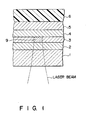
- FIG. 1 is a sectional view showing an information storage medium according to an embodiment of the present invention.
- a substrate 1 is formed of a transparent material whose characteristics do not change greatly over time, e.g., glass or a resin such as polycarbonate.
- a protective layer 2, a recording layer 3, a protective layer 4, a reflection layer 5, and a resin layer 6 are formed on the substrate 1 in that order.
- the protective layers 2 and 4 are formed of an inorganic dielectric material, and have the following functions:
- the reflection layer 5 is formed of a metal such as Au or Al, and has as its function the ability to reflect a reproduction laser beam and enhance a reproduction signal in cooperation with the protective layer 4.
- the resin layer 6 is formed of, e.g., an ultraviolet-curable resin, and its function is to prevent formation of scratches.
- the protective layers 2 and 4, the reflection layer 5, and the resin layer 6 are preferively formed but need not always be formed. In some instances, only one of the protective layers 2 and 4 may be formed.
- the recording layer 3 contains an alloy having a composition represented by (In 100-x Sb x ) 100-y Te y (wherein x and y are in atomic %, 45 ⁇ x ⁇ 50, and 25 ⁇ y ⁇ 45).
- This composition falls within the hatched range in Fig. 2, and an alloy having this composition can satisfy the requirements of high-speed crystallization and amorphous transformation, and allow a one-beam overwrite operation. The reason for this will be described below.
- an In50Sb50 intermetallic compound has a very short crystallization time. According to the experiments of the present inventors, the crystallization time was 45 nsec. Therefore, a composition based on the In50Sb50 intermetallic compound can allow high-speed crystallization. In a composition having a larger Sb content than that of the In50Sb50 intermetallic compound, Sb is excessively precipitated, resulting in very slow crystallization. In contrast to this, if a composition has a large In content, such a phenomenon does not occur. Therefore, not only in the In50Sb50 intermetallic compound but also in compositions having a slightly larger In content, a crystallization time can be shortened.
- the protective layers 2 and 4 are preferably formed of a material having a heat conductivity of 1/3 or more that of the recording layer 3.
- thermal conductivity k h of an InSbTe alloy is about 0.17 W/cm ⁇ °C
- materials satisfying the above-mentioned conditions include MgF2 having a thermal conductivity of about 0.1 W/cm ⁇ °C, Al2O3 of about 0.2 W/cm ⁇ °C, AlN of about 0.22 W/cm ⁇ °C, and the like.
- the protective layers 2 and 4 are preferably formed of crystalline materials.
- temperature control of the recording layer 3 can also be performed effectively, thus remarkably improving the overwrite characteristics.
- a recording layer is formed by a thin film formation technique such as sputtering, as is a protective layers.
- a thin film formation technique such as sputtering
- protective layers are formed by sputtering, these layers rapidly cool when they are deposited on a substrate, forming layers which normally become amorphous.
- An amorphous recording layer is initially crystallized upon radiation of a laser beam when the medium having the recording layer is used.
- dielectric materials normally used as a protective layer have a very high crystallization temperature
- an amorphous protective layer is directly used.
- thermal conductivity as a general physical value in an amorphous state is about 1/10 less than that in a crystalline state. Therefore, if the protective layers 2 and 4 are in an amorphous state, the recording layer cannot be rapidly cooled, and sufficient overwrite characteristics may not be obtained. If the protective layers 2 and 4 can be in their crystalline states, the above drawbacks can be avoided.
- the protective layer materials which can be formed into films in their crystalline states by a thin film technique such as sputtering include CeO2, PbO, ZnS, MgF2, and the like. Of these materials, CeO2 is most preferable.
- CeO2 has a thermal conductivity k h as high as about 0.08 W/cm ⁇ °C, and is about 1/2 that (0.17 W/cm ⁇ °C) of an InSbTe alloy. Thus, a good temperature control effect can be obtained.
- the thickness of the recording layer 3, the protective layers 2 and 4, the reflection layer 5 and the resin layer 6 preferably fall within the range of 50 ⁇ to 2000 ⁇ , 100 ⁇ to 5000 ⁇ , 50 ⁇ to 5000 ⁇ , and 1 ⁇ m to 50 ⁇ m respectively.
- the suitably-shaped substrate 1 (disk-like shape for an optical disk) is placed in the vacuum chamber of a sputtering apparatus, and the interior of the chamber is evacuated to a high vacuum.
- An argon gas is then introduced into the chamber, and argon sputtering is executed using a target formed of the material to be used as a protective layer.
- the protective layer 2 is formed on the substrate 1.
- Three-element co-sputtering of targets formed of constituting elements of the recording layer, or sputtering of an alloy target adjusted to the composition of the recording layer to be obtained in advance is executed while the atmosphere in the chamber remains the same as the atmosphere for the protective layer formation, thus forming the recording layer 3.
- the protective layer 4 is formed in the same manner as the protective layer 2.
- a desired metal target is sputtered to form the reflection layer 5.
- the substrate is removed from the sputtering apparatus, an ultraviolet-curable resin is applied on the reflection layer 5 by spin-coating, and an ultraviolet ray is radiated on the applied resin to form the resin layer 6.
- the recording layer 3 Since the recording layer 3 is normally in an amorphous state as deposited, the recording layer 3 is continuously irradiated with a laser beam and is heated beyond crystallization temperature to allow formation of an amorphous recording mark. Thereafter, the recording layer is gradually cooled so as to be transformed to a crystalline state.
- a laser beam is power-modulated between a high recording level P W and an erasure power level P E , lower than the recording level, as shown in Fig. 3, and is radiated onto the recording layer 3.
- a recording operation is performed by the laser beam of the level P W to form a recording mark 9 in the recording layer 3.
- new information is overwritten while erasing recorded information by the laser beam of the level P E .
- the disk is rotated at a predetermined speed, and a recording beam of the power level P W is radiated onto a region to be overwritten.
- a portion onto which no recording beam is radiated is irradiated with the beam of the erasure power level P E .
- the recorded amorphous recording mark 9 is transformed to the crystalline phase, thus erasing information.
- the portion irradiated with the beam of the level P W is transformed to the amorphous phase, thus forming the recording mark 9.
- a laser beam having a lower power level than P E is radiated onto the recording layer 3, and the difference between reflected light intensities of the recording mark 9 and the non-recorded portion is detected by a photoelectric transducer.
- a grooved polycarbonate 5" disk-like substrate was set in a vacuum chamber of a three-element sputtering apparatus, and a radio-frequency (R.F.) power was applied to an SiO2 target to perform argon gas sputtering. As a result, a 600 ⁇ thick SiO2 film was formed as a protective layer on the substrate.
- R.F. radio-frequency
- An R.F. power was applied to an In50Sb50 intermetallic compound target and a pure Te target to perform co-sputtering in an argon gas, thus forming a 400- ⁇ thick recording layer.
- the R.F. power was adjusted in advance so that the recording layer had a predetermined composition represented by (In 100-x Sb x ) 100-y Te y .
- the disk was removed from the sputtering apparatus, and was set on a spinner.
- An ultraviolet-curable resin was coated on the disk to have a thickness of about 10 ⁇ m. Ultraviolet rays were radiated onto the applied resin to cure it, thus forming a resin layer.
- composition of the recording layer was changed to prepare a plurality of optical disk samples.
- a track of the recording layer which was amorphous as deposited was transformed to a crystalline state by radiating a continuous laser beam having a power of 14 mW onto the surface of the recording layer.
- the same track was scanned three times with the laser beam in order to fully transform this portion to its crystalline phase.
- the first recording was performed by a pulse laser having an overwrite waveform as shown in Fig. 3.
- information was recorded on the crystalline track by a recording pulse having a power of 18 mW, a frequency of 4 MHz, and a duty ratio of 50%.
- the erasure biasing power was set at 14 mW.
- a 0.8 mW reproduction laser beam was radiated onto the groove of the recording layer to reproduce the recorded information.
- the reproduction signal was A/D-converted, and the C/N value of the digital signal was measured by a spectrum analyzer.
- a 0.8 mW reproduction laser beam was radiated onto the groove of the recording layer again to reproduce the recorded information.
- the reproduction signal was A/D-converted, and the C/N value of the digital signal was measured by the spectrum analyzer, then the C/N value of a recording mark at the previous frequency of 4 MHz and the degree of erasure of the previous recording mark were measured.
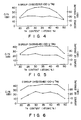
- Figs. 4 to 8 show the measurement results.
- Figs. 4 to 8 are graphs showing the relationships between Te contents and C/N values, and degrees of erasure of the A to E groups, in which the abscissa represents the Te content, the left ordinate and unbroken line represent the C/N value, and the right ordinate and broken line represent the degree of erasure.
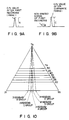
- the C/N value and the degree of erasure will be explained below with reference to Figs. 9A and 9B.
- the C/N value of a reproduction signal after the first recording (4 MHz) is represented by A
- the C/N value of a reproduction signal after the overwrite operation (5 MHz) is represented by C
- the C/N value of a non-erased signal of the first recording, which is not erased after the overwrite operation is represented by B.
- B-A corresponds to the degree of erasure
- C corresponds to the C/N value.
- optical disk samples were prepared following the same procedures as for those in Experimental Example 1, except that the two SiO2 layers serving as the protective layers were replaced with 400- ⁇ thick Al2O3 layers.
- Figs. 11 to 15 are graphs showing the relationships between Te contents, C/N values and degrees of erasure of the A to E groups, in which the abscissa represents the Te content, the left ordinate and unbroken line represent the C/N value and the right ordinate and broken line represent the degree of erasure.
- the composition of which is represented by (In 100-x Sb x ) 100-y Te y good overwrite characteristics can be obtained within the ranges of 45 ⁇ x ⁇ 50 and 25 ⁇ y ⁇ 45 as in Experimental Example 1.
- the C/N value and the degree of erasure in this composition range were improved from those in Experimental Example 1.
- the superiority of use of Al2O3 as a protective layer was demonstrated.
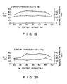
- Figs. 16 to 20 are graphs showing the relationships between Te contents, C/N values and degrees of erasure of the A to E groups, in which the abscissa represents the Te content, the left ordinate and unbroken line represent the C/N value and the right ordinate and broken line represent the degree of erasure.
Landscapes
- Chemical & Material Sciences (AREA)
- Inorganic Chemistry (AREA)
- Optical Record Carriers And Manufacture Thereof (AREA)
- Thermal Transfer Or Thermal Recording In General (AREA)
Applications Claiming Priority (6)
| Application Number | Priority Date | Filing Date | Title |
|---|---|---|---|
| JP1169612A JPH0334887A (ja) | 1989-06-30 | 1989-06-30 | 情報記録媒体 |
| JP169611/89 | 1989-06-30 | ||
| JP169612/89 | 1989-06-30 | ||
| JP169610/89 | 1989-06-30 | ||
| JP1169610A JPH0335438A (ja) | 1989-06-30 | 1989-06-30 | 情報記録媒体 |
| JP1169611A JPH0335439A (ja) | 1989-06-30 | 1989-06-30 | 情報記録媒体 |
Publications (2)
| Publication Number | Publication Date |
|---|---|
| EP0405225A2 true EP0405225A2 (de) | 1991-01-02 |
| EP0405225A3 EP0405225A3 (en) | 1992-02-26 |
Family
ID=27323200
Family Applications (1)
| Application Number | Title | Priority Date | Filing Date |
|---|---|---|---|
| EP19900111119 Withdrawn EP0405225A3 (en) | 1989-06-30 | 1990-06-12 | Information storage medium |
Country Status (2)
| Country | Link |
|---|---|
| EP (1) | EP0405225A3 (de) |
| KR (1) | KR910001684A (de) |
Families Citing this family (1)
| Publication number | Priority date | Publication date | Assignee | Title |
|---|---|---|---|---|
| KR102318731B1 (ko) * | 2019-12-27 | 2021-10-28 | 넥센타이어 주식회사 | 밸런스 웨이트 자동분출 시스템 및 장치 |
Family Cites Families (3)
| Publication number | Priority date | Publication date | Assignee | Title |
|---|---|---|---|---|
| US4818666A (en) * | 1986-03-28 | 1989-04-04 | U.S. Philips Corporation | Erasable optical recording element and method of optically recording and erasing information |
| EP0307750B2 (de) * | 1987-09-14 | 1995-11-22 | Kabushiki Kaisha Toshiba | Gebrauch eines Speichermediums in einem Verfahren zur Aufnahme von Informationen |
| JPH081707B2 (ja) * | 1987-12-04 | 1996-01-10 | 松下電器産業株式会社 | 光学的情報記録媒体 |
-
1990
- 1990-06-12 EP EP19900111119 patent/EP0405225A3/en not_active Withdrawn
- 1990-06-30 KR KR1019900009889A patent/KR910001684A/ko not_active Ceased
Also Published As
| Publication number | Publication date |
|---|---|
| KR910001684A (ko) | 1991-01-31 |
| EP0405225A3 (en) | 1992-02-26 |
Similar Documents
| Publication | Publication Date | Title |
|---|---|---|
| EP0574025B1 (de) | Optisches Aufzeichungsmedium und Verfahren zur Herstellung desselben | |
| US6242157B1 (en) | Optical recording medium and method for making | |
| US6153355A (en) | Optical recording medium and method for preparing the same | |
| US5688574A (en) | Optical recording medium | |
| US5637372A (en) | Phase change optical recording medium | |
| JP3566743B2 (ja) | 光記録媒体 | |
| US5523140A (en) | Optical recording method and medium | |
| US5637371A (en) | Phase change optical recording medium and activation energy determining method | |
| JPWO2000054982A1 (ja) | 情報記録媒体とその製造方法 | |
| EP1030292B1 (de) | Optischer Aufzeichnungsträger und Verfahren zu dessen Initialisierung | |
| EP0766862A1 (de) | Optische informationsträger | |
| JP2937351B2 (ja) | 第三元素を含有するアンチモン‐錫合金からなる光学記録材料 | |
| CN1230816C (zh) | 光记录介质 | |
| US5206114A (en) | Information storage medium containing a recording layer capable of exhibiting a dual phase state | |
| EP1398776A1 (de) | Optisches Aufzeichnungsmedium | |
| US5202881A (en) | Information storage medium | |
| JPH08124213A (ja) | 光記録媒体 | |
| EP0405225A2 (de) | Informationsspeicherungsmedium | |
| US5055331A (en) | Phase-change optical recording media | |
| EP0307750B1 (de) | Gebrauch eines Speichermediums in einem Verfahren zur Aufnahme von Informationen | |
| JP2674837B2 (ja) | 相変化型光ディスク | |
| JP3379256B2 (ja) | 光学的情報記録用媒体 | |
| JP3444037B2 (ja) | 光学的情報記録用媒体 | |
| JP2886188B2 (ja) | 情報記録媒体 | |
| JP3365457B2 (ja) | 光学的情報記録用媒体 |
Legal Events
| Date | Code | Title | Description |
|---|---|---|---|
| PUAI | Public reference made under article 153(3) epc to a published international application that has entered the european phase |
Free format text: ORIGINAL CODE: 0009012 |
|
| 17P | Request for examination filed |
Effective date: 19900709 |
|
| AK | Designated contracting states |
Kind code of ref document: A2 Designated state(s): DE FR GB NL |
|
| PUAL | Search report despatched |
Free format text: ORIGINAL CODE: 0009013 |
|
| AK | Designated contracting states |
Kind code of ref document: A3 Designated state(s): DE FR GB NL |
|
| 17Q | First examination report despatched |
Effective date: 19940624 |
|
| STAA | Information on the status of an ep patent application or granted ep patent |
Free format text: STATUS: THE APPLICATION IS DEEMED TO BE WITHDRAWN |
|
| 18D | Application deemed to be withdrawn |
Effective date: 19941105 |