EP0405228A1 - Halterung für schnell montierbare Sitzbänke oder Sitzträger, insbesondere von Tribünen - Google Patents
Halterung für schnell montierbare Sitzbänke oder Sitzträger, insbesondere von Tribünen Download PDFInfo
- Publication number
- EP0405228A1 EP0405228A1 EP90111153A EP90111153A EP0405228A1 EP 0405228 A1 EP0405228 A1 EP 0405228A1 EP 90111153 A EP90111153 A EP 90111153A EP 90111153 A EP90111153 A EP 90111153A EP 0405228 A1 EP0405228 A1 EP 0405228A1
- Authority
- EP
- European Patent Office
- Prior art keywords
- seat
- perforated
- support
- supports
- seats
- Prior art date
- Legal status (The legal status is an assumption and is not a legal conclusion. Google has not performed a legal analysis and makes no representation as to the accuracy of the status listed.)
- Granted
Links
- 238000003780 insertion Methods 0.000 claims abstract description 10
- 230000037431 insertion Effects 0.000 claims abstract description 10
- 239000002184 metal Substances 0.000 claims description 3
- 229910052751 metal Inorganic materials 0.000 claims description 3
- 239000002990 reinforced plastic Substances 0.000 claims description 2
- XEEYBQQBJWHFJM-UHFFFAOYSA-N Iron Chemical compound [Fe] XEEYBQQBJWHFJM-UHFFFAOYSA-N 0.000 description 8
- 229910052742 iron Inorganic materials 0.000 description 4
- 210000002414 leg Anatomy 0.000 description 3
- 238000010276 construction Methods 0.000 description 2
- 238000006073 displacement reaction Methods 0.000 description 2
- 229910000831 Steel Inorganic materials 0.000 description 1
- 230000005540 biological transmission Effects 0.000 description 1
- 238000004806 packaging method and process Methods 0.000 description 1
- 239000010959 steel Substances 0.000 description 1
- 210000000689 upper leg Anatomy 0.000 description 1
Images


Classifications
-
- E—FIXED CONSTRUCTIONS
- E04—BUILDING
- E04H—BUILDINGS OR LIKE STRUCTURES FOR PARTICULAR PURPOSES; SWIMMING OR SPLASH BATHS OR POOLS; MASTS; FENCING; TENTS OR CANOPIES, IN GENERAL
- E04H3/00—Buildings or groups of buildings for public or similar purposes; Institutions, e.g. infirmaries or prisons
- E04H3/10—Buildings or groups of buildings for public or similar purposes; Institutions, e.g. infirmaries or prisons for meetings, entertainments, or sports
- E04H3/12—Tribunes, grandstands or terraces for spectators
Definitions
- the invention relates to a holder for quickly assembled benches or seat supports, in particular grandstands, wherein the seats or seat supports can be placed on horizontal seat holders and secured by means of a plug connection
- an upwardly projecting tab is provided, through the hole of which a hook part fastened to the next seat can be suspended. This requires lifting each seat at the end without a hook part and inserting the hook part at the other end into the tab of the next seat. This requires a lot of assembly work, usually with two people. In addition, the hook part in the seating area is annoying.
- DE 85 33 418 U1, DE 82 32 782 U1, DE 78 10 046 U1, DE 70 03 435 U1, DE 19 82 570 U1 and DE 19 29 665 show the most varied seating furniture designs in which the horizontally extending slats with the most varied Connecting and screwing means are connected to the frame, but have nothing to do with the special design according to the invention.
- US Pat. No. 2,611,422 shows a grandstand system in which lattice girders with the same gradient have vertical, upwardly open tubes onto which flange elements are attached, the bushings of which are secured with clamping screws guided laterally through them, and on the flanges of which the benches are placed and screwed down from above will.
- the operation of the screws requires considerable assembly effort and is not comparable to the clamping system according to the invention.
- the invention has for its object to provide a quick to assemble and disassemble and safe to use, simply constructed connection between the seat holder and the bench or seat support.
- the bench seats in the region of their ends preferably have a slot, into which the perforated tabs can be inserted from above and can be pushed through a recess in the bench support and the wedge is provided transversely under the bench support and the perforated tabs in the area of the edges of the seat opening are each provided with support supports.
- the invention can also be described as follows: Holder for quickly assembled benches or seat supports, in particular for grandstands, the seats or seat supports can be placed on the seat holder and secured by means of a plug connection, and the plug connection is equipped with a perforated tab that engages with one another with a form-fitting securing element that engages them a perforated bracket support is assigned to the seat or the seat support in the support area, to which the perforated bracket part engages and a wedge is provided which extends transversely through the perforated bracket and compresses the parts lying on top of one another.
- the perforated plate is designed as a flat part provided with a rectangular wedge hole, which is rotated by 90 ° to the longitudinal axis of a flat part serving as a perforated plate support or welded to it or formed on it.
- the benches each consist of two wooden boards or other seating elements fastened at a distance to connecting parts, for example made of reinforced plastics or light metal profiles, which are united at the end with the connecting parts to form a slot between them, the The width of the slots corresponds to the thickness of the perforated plate supports and the bench supports supporting them have recesses for the perforated plates to be passed through.
- the bench supports have stops in the middle on their upper support surfaces with a thickness corresponding to the perforated tabs, on which the connecting parts of the seats or the like are located. secure them axially and form a gap for the perforated tabs
- the seat holder has a front front support which can be plugged onto a running floor holder and a rear tubular support which is equipped with an insertion end for an upwardly open pipe opening of a pipe section of a grandstand cheek part and which has the bench support connected to form a portal-like support base for the benches or seat supports.
- the bracket 130 for quickly assembled benches 131 shows, for example, benches 131 made of two individual boards 132.1 and 132.2, which are connected at their ends by means of screws 134 designed as flat iron connecting parts 133.
- benches instead of benches, seat supports with individual, attached seat shells or the like can also be provided.
- the seat holder 135 has a round tube support 136, which is located in the front area. This has at its lower end 136.1 a U-shaped, downwardly open leg clamp 137, which is placed over a tread holder 111 and is secured with a screw 138 or a bolt or other securing means underneath which prevents it from being lifted upwards.
- the seat holder 135 has a rectangular tubular support 141 at the rear, the lower end 142 of which is inserted between the legs 111.1 and 111.2 of the tread holder 111. The lower end is supported on the web of the upwardly open U-shaped tread bracket 111.
- the walking floor holder 111 is fastened to a pipe section 140.4 of a cheek part of a grandstand, which is not shown in further detail.
- the seat holder 135 is fastened on the rear side of the cheek part by carrying an insertion tube 145 on the rear wall 146 of the rear tube support 141.
- the insertion tube 145 is mounted at such a height that the insertion end 145.1 fits exactly into the upper end 147 of the tube piece 140.4.
- Be Fastening part 145.2 is welded to the pipe support 141 with the aid of the weld seams 148, as can be seen from FIGS. 1 and 4.
- the two pipe supports 136 and 141 are connected at the top by a bench support 155 formed by a flat iron. This is welded on with the aid of the weld seams 156.
- stops 157 are formed or welded over the pipe supports in the area of both ends, which, when the connecting parts 133 are placed, from two rows of benches 131 arranged in a row on a common bench support 155 for axially fixing the two benches and for creating a slot serve for the perforated plate 150.
- the bench support 155 has a recess 160 in the middle, which serves to push through the perforated plate 150 of a cross-shaped holding element 149.
- the holding element 149 is designed in such a way that its perforated bracket support 163 can be inserted from above through the slots 162 between the two boards 132.1 and 132.2 of the two bench seats 131.
- the perforated plate support 163 has securing arms 164 at its two ends, which protrude downward next to the bench support 155, as shown in particular in FIG. 3.
- the perforated plate 150 is welded downward on the perforated plate support 163, the perforated plate support 163 being inserted into a fastening slot 165 of the flat iron forming the perforated plate 150, and both parts using the weld seams 167 in this way are welded that a cross-shaped holding element 149 results.
- the wedge hole 166 is recessed vertically, as shown in the figures, so that it lies below the bench support 155 when the holding element 149 is inserted. Then, as can be seen from FIGS. 1, 3 and 7, the wedge 152 can be inserted and secured. It is supported on the lower edge 166.1 of the wedge hole 166 and the underside 155.1 of the bench support 155 and holds the holding element 149 firmly downward. As a result, the two connecting parts 133.1 and 133.2 are firmly pressed onto the bench support 155. At the same time, they are secured against axial displacement between the stops 157. This results in a small gap 168 between the ends of the individual benches. Its thickness corresponds to the thickness of the perforated tabs 150.
- the components are made of steel pipes and flat iron, welded together and galvanized. For special designs, they can also be made from extruded light metal profiles.
- the support devices can be adapted to the respective needs of the grandstand construction or the other base frame construction. It is important that a perforated plate or another component that is permitted to be attached to a securing element is inserted from above through slots and / or openings and secured from below with a quick securing device.
- the holder (130) carries benches (131), the boards (132.1, 132.2) of which are connected by connecting parts (133). These rest on the bench support (155) of the seat holder (135). Stops (157) fix them in the axial direction and form a gap between the ends.
- a holding element (149) has a perforated bracket support (163) and a perforated bracket (150). These are inserted through the slot (162) and the recess (160) of the bench support, so that the perforated plate support (163) supported on the connecting parts (133) and a wedge (152) under the bench support (155) through the perforated plate (150) is secured to secure the connection.
- the seat holder (135) is supported with its front pipe support (136) and a foot clamp (137) on a running floor holder (111) at the front.
- a rear pipe support (141) is supported with its lower end (142) in the upwardly open U-profile of the tread holder (111) and has an insertion tube (145), the insertion end of which into the upper end (147) of a piece of tube (140.4) of a cheek part of a grandstand intervenes.
Landscapes
- Engineering & Computer Science (AREA)
- Architecture (AREA)
- Civil Engineering (AREA)
- Structural Engineering (AREA)
- Special Chairs (AREA)
- Valve-Gear Or Valve Arrangements (AREA)
- Clamps And Clips (AREA)
- Molds, Cores, And Manufacturing Methods Thereof (AREA)
- Preparing Plates And Mask In Photomechanical Process (AREA)
- Hooks, Suction Cups, And Attachment By Adhesive Means (AREA)
- Vehicle Step Arrangements And Article Storage (AREA)
- Passenger Equipment (AREA)
- Connection Of Plates (AREA)
- Tents Or Canopies (AREA)
- Automatic Cycles, And Cycles In General (AREA)
Abstract
Description
- Die Erfindung betrifft eine Halterung für schnell montierbare Sitzbänke oder Sitzträger, insbesondere von Tribünen, wobei die Sitzbänke oder Sitzträger auf horizontale Sitzbank-Halter auflegbar und mittels einer Steckverbindung sicherbar sind
- Bei Tribünen oder anderen Anlagen mit Sitzbänken oder Halterungen für Sitze, beispielsweise Schalensitze, werden langgestreckte Elemente in der Regel im Bereich ihrer Enden abgestützt. Damit sie von den Untergestellen, inbesondere der Tribünen-Tragkonstruktion durch Benutzer nicht ohne weiteres abgehoben werden, so daß andere Besucher zu Boden fallen, sind geeignete Abstützungen und Verbindungen vorzusehen, die wegen der Verwendung an verschiedenen Orten jedoch schnell zu montieren, d.h. zusammenzubauen und in den Sicherungszustand zu bringen sein müssen und die andererseits sehr schnell zu demontieren sein sollen. Bisher wurden solche Verbindungen in der Regel mit Schrauben und Muttern realisiert (DE-GM 1 973 139, Fig. 8 und Seiten 6/7; US-PS 2,611,422, Fig. 13). Bei der Ausführung nach DE-OS 35 19 718 sind die Bänke nur lose auf Sitzbank-Haltern aufgelegt und gegen seitliche Verschiebung mit Stiften gesichert. Bei der Ausführung nach GB-PS 898 121 ist eine nach oben ragende Lasche vorgesehen, durch deren Loch ein an der nächsten Sitzbank befestigtes Hakenteil einhängbar ist. Dieses erfordert das Anheben jeder Sitzbank an dem ohne Hakenteil ausgestatteten Ende und das Einführen des Hakenteiles am anderen Ende in die Lasche der nächsten Sitzbank. Das erfordert einen großen Montageaufwand, in der Regel mit zwei Personen. Außerdem ist das Hakenteil im Sitzbereich lästig.
- Vom Deutschen Patentamt wurden nur die im Folgenden abgehandelten, zum Teil vorn genannten Schriften zum technologischen Hintergrund des Anmeldungsgegenstandes aufgeführt.
- DE 85 33 418 U1, DE 82 32 782 U1, DE 78 10 046 U1, DE 70 03 435 U1, DE 19 82 570 U1 und DE 19 29 665 zeigen die verschiedensten Sitzmöbel-Gestaltungen, bei denen die horizontal verlaufenden Latten mit den verschiedensten Verbindungs- und Schraubmittel mit dem Gestell verbunden sind, die jedoch mit der speziellen Ausgestaltung nach der Erfindung nichts zu tun haben.
- Bei der Nennung von DE 19 73 138 U1 handelt es sich um einen Übermittlungsfehler, da diese Schrift einen höhenverstellbaren Gerätewagen für Fliesenleger und verwandte Berufe behandelt, dessen konstruktive Gestaltung nichts mit der Erfindung gemeinsam hat.
- US-PS 2,611,422 zeigt eine Tribünenanlage, bei der mit gleicher Steigung verlaufende Gitterträger vertikale, nach oben offene Rohre aufweisen, auf welche Flanschelemente aufgesteckt sind, deren Büchsen mit seitlich durch sie geführten Klemmschrauben gesichert werden und auf deren Flansche die Bänke von oben aufgelegt und festgeschraubt werden. Die Betätigung der Schrauben erfordert beträchtlichen Montageaufwand und ist mit dem Klemmsystem nach der Erfindung nicht vergleichbar.
- DE 35 19 718 A1 und GB 898 121 = DE-OS 14 09 400 wurden schon vorn abgehandelt.
- Der Erfindung liegt die Aufgabe zugrunde, eine schnell montierbare und demontierbare sowie für die Benutzung sichere, einfach aufgebaute Verbindung zwischen den Sitzbank-Haltern und den Sitzbänken oder Sitzträgern zu schaffen.
- Erfindungsgemäß ist vorgesehen, daß die Sitzbänke im Bereich ihrer Enden Sitzbank-Öffnungen, vorzugsweise jeweils einen Schlitz aufweisen, in welche von oben die Lochlaschen einführbar und jeweils durch eine Ausnehmung in der Bankauflage durchsteckbar sind und wobei der Keil jeweils unter der Bankauflage querliegend vorgesehen ist und die Lochlaschen im Bereich der Ränder der Sitzbank-Öffnung jeweils mit Auflagestützen versehen sind.
- In einer anderen Form der Definition kann man die Erfindung auch wie folgt beschreiben:
Halterung für schnell montierbare Sitzbänke oder Sitzträger, insbesondere von Tribünen, wobei die Sitzbänke oder Sitzträger auf Sitzbank-Halter auflegbar und mittels Steckverbindung sicherbar sind und wobei die Steckverbindung mit einer durch aufeinanderliegende Teile greifenden Lochlasche mit einem an sie angreifenden, formschlüssigen Sicherungselement ausgestattet ist, wobei der Sitzbank bzw dem Sitzträger im Stützbereich eine Lochlaschen-Abstützung zugeordnet ist, an welche das Lochlaschen-Teil angreift und wobei ein die Lochlasche querliegend durchgreifender, die aufeinanderliegenden Teile zusammendrückender Keil vorgesehen ist. - Dadurch, daß man nun eine Lochlasche verwendet, die sinnvoll eingeführt und durch deren Loch ein Keil durchgesteckt wird, hat man eine sehr schnell und sicher montierbare Verbindung, die wegen des Einschlagens des Keiles vom normalen Benutzer, auch von Kindern nicht ohne weiteres gelockert werden kann, so daß Gefahr für die die Tribüne od. dgl. benutzenden Personen nicht besteht. Die Verbindung ist im Zusammenbauzustand fest und kann zur Demontage einfach gelöst werden. Es gibt verschiedene Ausführungsmöglichkeiten, je nachdem, wo man die Lochlasche befestigen und/oder abstützen will.
- In einer bevorzugten Ausführungsform der Erfindung kann vorgesehen sein, daß die Lochlasche als mit einem rechteckigen Keilloch versehenes Flachteil ausgebildet ist, welches um 90° zur Längsachse eines als Lochlaschen-Abstützunng dienenden Flachteiles gedreht an dieses angeschweißt oder an diesem ausgeformt ist.
- In einer weiteren bevorzugten Ausführungsform der Erfindung kann vorgesehen sein, daß die Sitzbänke jeweils aus zwei mit Abstand auf Verbindungsteilen befestigten Holzbrettern oder sonstigen Sitzelementen, beispielsweise aus verstärkten Kunststoffen oder Leichtmetallprofilen bestehen, die endseitig mit den Verbindungsteilen einen Schlitz zwischen ihnen bildend vereinigt sind, wobei die Breite der Schlitze der Stärke der Lochlaschen-Abstützungen entspricht und die sie abstützenden Bankauflagen Ausnehmungen zum Durchführen für die Lochlaschen aufweisen.
- In einer weiteren bevorzugten Ausführungsform der Erfindung kann vorgesehen sein, daß die Bankauflagen auf ihren oberen Auflageflächen mittig Anschläge mit einer den Lochlaschen entsprechenden Stärke aufweisen, an denen sich die Verbindungsteile der Sitzbänke od.dgl. sie axial sichernd und einen Spalt für die Lochlaschen bildend abstützen
- In einer weiteren bevorzugten Ausführungsform der Erfindung kann vorgesehen sein, daß der Sitzbank-Halter eine vordere auf einen Laufboden-Halter aufsteckbare Vorderstütze und eine mit einem Einsteckende für eine nach oben offene Rohröffnung eines Rohrstückes eines Tribünen-Wangenteiles ausgestattete hintere Rohrstütze aufweist die mit der Bankauflage verbunden eine portalartige Stützbasis für die Sitzbänke oder Sitzträger bilden.
- Eine bevorzugte Ausführungsformen der Erfindung ist in dem nachfolgenden, anhand der Zeichnungen abgehandelten Beschreibungsteil mit weiteren Merkmalen, Vorteilen und Gesichtspunkten der Erfindung behandelt.
- Ein Ausführungsbeispiel wird anhand der Zeichnung erläutert.
- Es zeigen:
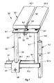
- Fig. 1 Eine schematisierte Teil-Schrägansicht eines Sitzbank-Endes auf einer Halterung für zwei aneinander anstoßende Sitzbänke, von denen nur eine dargestellt ist, mit von oben durchsteckbarer Lochlaschen-Keilsicherung;
- Fig. 2 einen Vertikalschnitt durch die Anordnung nach Fig. 1;
- Fig. 3 einen um 90° zu der Anordnung in Fig. 1 und 2 gedrehten Vertikalschnitt, der zusammengebauten Anordnung mit zwei Sitzbankenden, wobei die hinter der Zeichenebene liegenden Teile weggelassen sind;
- Fig. 4 die Seitenansicht des Sitzbank-Halters;
- Fig. 5 eine Draufsicht auf den Sitzbank-Halter nach Fig. 4;
- Fig. 6 einen Vertikalschnitt durch das Ende einer Sitzbank im Bereich der das Verbindungsteil befestigenden Schrauben in etwas größerem Maßstab als die übrigen Zeichnuungen;
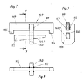
- Fig. 7 die Seitenansicht eines kreuzförmigen Halteelementes mit Lochlaschen-Abstützung und Lochlasche;
- Fig. 8 die Draufsicht auf das Halteelement nach Fig. 7
und - Fig. 9 ein Vertikalschnitt längs der Linie 9-9 in Fig.7 durch das Halteelement mit Darstellung der Lochlasche.
- Die Halterung 130 für schnell montierbare Sitzbänke 131 zeigt beispielsweise Sitzbänke 131 aus zwei einzelnen Brettern 132.1 und 132.2, die durch als Flacheisen ausgebildete Verbindungsteile 133 an ihren Enden mit Hilfe von Schrauben 134 verbunden sind. Anstelle von Sitzbänken können auch Sitzträger mit einzelnen, aufgesetzten Sitzschalen oder dgl. vorgesehen sein.
- Der Sitzbank-Halter 135 hat eine runde Rohrstütze 136, die im Vorderbereich liegt. Diese hat an ihrem unteren Ende 136.1 eine U-förmig gebogene, nach unten offene Fußschelle 137, die über einen Laufboden-Halter 111 gesteckt ist und mit einer unter diesem durchgehenden Schraube 138 oder einem Bolzen oder einer sonstigen Sicherung gegen Abheben nach oben gesichert ist. Der Sitzbank-Halter 135 hat hinten eine rechteckförmige Rohrstütze 141, deren unteres Ende 142 zwischen den Schenkeln 111.1 und 111.2 des Laufboden-Halters 111 eingesteckt ist. Das untere Ende stützt sich auf dem Steg des nach oben offenes U-förmigen Laufboden-Halters 111 ab. Der Laufboden-Halter 111 ist an einem Rohrstück 140.4 eines im einzelnen nicht weiter dargestellten Wangenteiles einer Tribüne befestigt. Der Sitzbank-Halter 135 ist an dem Wangenteil rückseitig befestigt, indem er ein Einsteckrohr 145 an der Rückwand 146 der hinteren Rohrstütze 141 trägt. Das Einsteckrohr 145 ist in einer solchen Höhe angebracht, daß das Einsteckende 145.1 in das obere Ende 147 des Rohrstückes 140.4 genau hineinpaßt. Sein Befestigungsteil 145.2 ist mit Hilfe der Schweißnähte 148 an der Rohrstütze 141 angeschweißt, wie es aus den Fig. 1 und 4 ersichtlich ist.
- Die beiden Rohrstützen 136 und 141 sind oben durch eine von einem Flacheisen gebildete Bankauflage 155 verbunden. Diese ist mit Hilfe der Schweißnähte 156 angeschweißt. In der Mitte auf der oberen Auflagefläche sind über den Rohrstützen im Bereich beider Enden Anschläge 157 ausgebildet oder aufgeschweißt, die beim Auflegen der Verbindungsteile 133 von zwei sich aneinander reihenden Sitzbänken 131 auf eine gemeinsame Bankauflage 155 zur axialen Festlegung der beiden Sitzbänke und zur Schaffung eines Schlitzes für die Lochlasche 150 dienen. Die Bankauflage 155 hat in der Mitte eine Ausnehmung 160, die zum Durchstecken der Lochlasche 150 eines kreuzförmigen Halteelementes 149 dient. Das Halteelement 149 ist derart ausgebildet, daß seine Lochlaschen-Abstützung 163 sich durch die Schlitze 162 zwischen den beiden Brettern 132.1 und 132.2 der beiden Sitzbänke 131 von oben einstecken läßt. Die Lochlaschen-Abstützung 163 hat an ihren beiden Enden Sicherungsarme 164, die neben der Bankauflage 155 nach unten vorstehen, wie es insbesondere Fig. 3. zeigt. In der Mitte ist an der Lochlaschen-Abstützung 163 nach unten ragend die Lochlasche 150 angeschweißt, wobei die Lochlaschen-Abstützung 163 in einen Befestigungsschlitz 165 des die Lochlasche 150 bildenden Flacheisens eingesetzt ist und wobei beide Teile mit Hilfe der Schweißnähte 167 derart verschweißt sind, daß sich ein kreuzförmiges Halteelement 149 ergibt. Dabei ist das Keilloch 166 sich vertikal erstreckend ausgespart, wie es die Abbildungen zeigen, so daß es unterhalb der Bankauflage 155 liegt, wenn das Halteelement 149 eingesteckt ist. Dann kann - wie aus den Fig. 1, 3 und 7. ersichtlich - der Keil 152 eingesteckt und festgeschlagen werden. Er stützt sich an der Unterkante 166.1 des Keilloches 166 und der Unterseite 155.1 der Bankauflage 155 ab und hält das Halteelement 149 fest nach unten. Dadurch sind die beiden Verbindungsteile 133.1 und 133.2 fest auf die Bankauflage 155 aufgedrückt. Sie sind gleichzeitig zwischen den Anschlägen 157 gegen axiales Verschieben gesichert. Zwischen den Enden der einzelnen Sitzbänke ergibt sich dadurch ein kleiner Spalt 168. Seine Stärke entspricht der Stärke der Lochlaschen 150.
- Wenn man gleiche Sitzbankträger und dgl. auch an den Enden von langen Bankreihen verwenden will, so kann man kurze Blindstücke, die nur als kurze Brettstücke oder dgl. mit einem sie verbinden Verbindungsteil 133 ausgebildet sind, am jeweiligen Ende auflegen und gemeinsam mit dem Halteelement 149 und dem Keil 152 sichern. Die Herstellung des kreuzförmigen Halteelementes 149 ist äußerst einfach. Auf den Sitzbank-Haltern 135 gibt es keine nennenswert nach oben überstehenden Teile, die bei Verpackung, Transport und Aufbau stören könnten und trotzdem ergibt sich eine einfache Durchsteck- und Keilverbindung, die sowohl leicht eingesetzt und durch Einschlagen des Keiles gesichert als auch durch Lockern und Herausziehen des Keiles leicht wieder von Montagepersonen gelöst werden kann. Sie ist jedoch von den Besuchern nicht ohne weiteres zu öffnen, so daß die Gefahr von Verschiebungen der Sitzbänke oder der Sitzhalter gering ist. Die Bauteile werden aus Stahlrohren und Flacheisen gefertigt, zusammengeschweißt und verzinkt. Sie können für besondere Ausführen auch aus Leichtmetall-Strang-Preß-Profilen gefertigt sein. Die Stützeinrichtungen können den jeweiligen Bedürfnissen der Tribünenkonstruktion oder der sonstigen Fußgestellkonstruktion sinngemäß angepaßt werden. Wichtig ist, daß eine Lochlasche oder eine sonstige, ein Sicherungselement anzulegen gestattendes Bauteil von oben durch Schlitze und/oder Öffnungen eingeführt und von unten mit einer Schnellsicherung festgelegt wird.
- Die nachfolgend abgedruckte Zusammenfassung ist Bestandteil der Offenbarung der Erfindung:
Die Halterung (130) trägt Sitzbänke (131), deren Bretter (132.1, 132.2) durch Verbindungsteile (133) verbunden sind. Diese liegen auf der Bankauflage (155) des Sitzbank-Halter (135) auf. Anschläge (157) fixieren sie in axialer Richtung und bilden einen Spalt zwischen den Enden. Ein Halteelement (149) hat eine Lochlaschen-Abstützung (163) und eine Lochlasche (150). Diese werden durch den Schlitz (162) und die Ausnehmung (160) der Bankauflage eingeführt, so daß sich die Lochlaschen-Abstützung (163) auf den Verbindungsteilen (133) abstützt und ein Keil (152) unter der Bankauflage (155) durch die Lochlasche (150) die Verbindung sichernd eingeschlagen wird. Der Sitzbank-Halter (135) ist mit seiner vorderen Rohrstütze (136) und einer Fußschelle (137) auf einem Laufboden-Halter (111) vorn abgestützt. Eine hintere Rohrstütze (141) stützt sich mit ihrem unteren Ende (142) in dem nach oben offenen U-Profil des Laufboden-Halters (111) ab und hat ein Einsteckrohr (145), dessen Einsteckende in das obere Ende (147) eines Rohrstückes (140.4) eines Wangenteiles einer Tribüne sichernd eingreift. -
- 111 Laufboden-Halter
- 111.1 Schenkel
- 111.2 Schenkel
- 130 Halterung
- 131 Sitzbank
- 132.1 Brett
- 132.2 Brett
- 133 Verbindungsteil
- 133.1 Verbindungsteil
- 133.2 Verbindungsteil
- 134 Schraube
- 135 Sitzbank-Halter
- 136 Rohrstütze
- 136.1 unteres Ende von 136
- 137 Fußschelle
- 138 Schraube
- 140.4 Rohrstück
- 141 Rohrstütze
- 142 unteres Ende von 140
- 145 Einsteckrohr
- 145.1 Einsteckende
- 145.2 Befestigungsteil
- 146 Rückwand von 140
- 147 oberes Ende von 140.4
- 148 Schweißnaht
- 149 Halteelement
- 150 Lochlasche
- 152 Keil
- 155 Bankauflage
- 155.1 Unterseite
- 156 Schweißnaht
- 157 Anschlag
- 160 Ausnehmung
- 162 Schlitz
- 163 Lochlaschen-Abstützung
- 164 Sicherungsarm
- 165 Befestigungsschlitz
- 166 Keilloch
- 166.1 Unterkante
- 167 Schweißnaht
- 168 Spalt
Claims (6)
dadurch gekennzeichnet, daß die Sitzbänke (131) im Bereich ihrer Enden Sitzbank-Öffnungen (162, 168), vorzugsweise jeweils einen Schlitz aufweisen, in welche von oben die Lochlaschen (150) einführbar und jeweils durch eine Ausnehmung (160) in der Bankauflage (155) durchsteckbar sind und wobei der Keil (152) jeweils unter der Bankauflage (155) querliegend vorgesehen ist und die Lochlaschen (150) im Bereich der Ränder der Sitzbank-Öffnung jeweils mit Auflagestützen (163) versehen sind.
Priority Applications (1)
| Application Number | Priority Date | Filing Date | Title |
|---|---|---|---|
| AT90111153T ATE83825T1 (de) | 1989-06-24 | 1990-06-13 | Halterung fuer schnell montierbare sitzbaenke oder sitztraeger, insbesondere von tribuenen. |
Applications Claiming Priority (2)
| Application Number | Priority Date | Filing Date | Title |
|---|---|---|---|
| DE3920792 | 1989-06-24 | ||
| DE3920792A DE3920792A1 (de) | 1989-06-24 | 1989-06-24 | Halterung fuer schnell montierbare sitzbaenke oder sitztraeger, insbesondere von tribuenen |
Publications (2)
| Publication Number | Publication Date |
|---|---|
| EP0405228A1 true EP0405228A1 (de) | 1991-01-02 |
| EP0405228B1 EP0405228B1 (de) | 1992-12-23 |
Family
ID=6383533
Family Applications (1)
| Application Number | Title | Priority Date | Filing Date |
|---|---|---|---|
| EP90111153A Expired - Lifetime EP0405228B1 (de) | 1989-06-24 | 1990-06-13 | Halterung für schnell montierbare Sitzbänke oder Sitzträger, insbesondere von Tribünen |
Country Status (8)
| Country | Link |
|---|---|
| EP (1) | EP0405228B1 (de) |
| AT (1) | ATE83825T1 (de) |
| DE (2) | DE3920792A1 (de) |
| DK (1) | DK0405228T3 (de) |
| ES (1) | ES2038468T3 (de) |
| FI (1) | FI91657C (de) |
| NO (1) | NO176681C (de) |
| PT (1) | PT94461B (de) |
Cited By (1)
| Publication number | Priority date | Publication date | Assignee | Title |
|---|---|---|---|---|
| FR2754005A1 (fr) * | 1996-09-30 | 1998-04-03 | Chaudronnerie Metallerie Du Mi | Tribunes et gradins demontables et procede de renforcement des tribunes et gradins |
Citations (3)
| Publication number | Priority date | Publication date | Assignee | Title |
|---|---|---|---|---|
| BE530409A (de) * | ||||
| NL48739C (de) * | 1900-01-01 | |||
| GB898121A (en) * | 1959-09-11 | 1962-06-06 | Plet Margadant | Stand or like staging structure |
Family Cites Families (6)
| Publication number | Priority date | Publication date | Assignee | Title |
|---|---|---|---|---|
| US2611422A (en) * | 1947-07-28 | 1952-09-23 | Safway Steel Products Inc | Demountable grandstand seat planks |
| CH389225A (de) * | 1959-12-07 | 1965-03-15 | Huennebeck Emil Mauritz Dipl I | Klammer zum lösbaren Verbinden zweier Teile |
| DE7810046U1 (de) * | 1978-04-05 | 1978-07-13 | Pag Presswerk Ag, 4300 Essen | Mehrsitzelement fuer reihenbestuhlungen |
| DE8232782U1 (de) * | 1982-11-23 | 1983-05-05 | Karl Münkel GmbH & Co KG, 4837 Verl | Gartenbank mit zwei das sitzteil und die rueckenlehne tragenden bankfuessen |
| DE3519718C2 (de) * | 1985-06-01 | 2001-03-08 | Geb Layher Langer | Tragkonstruktion für Tribünen |
| DE8533418U1 (de) * | 1985-11-27 | 1986-02-13 | Plantener Ausstattungssysteme GmbH, 8080 Fürstenfeldbruck | Sitzmöbel |
-
1989
- 1989-06-24 DE DE3920792A patent/DE3920792A1/de not_active Withdrawn
-
1990
- 1990-06-11 NO NO902577A patent/NO176681C/no not_active IP Right Cessation
- 1990-06-13 EP EP90111153A patent/EP0405228B1/de not_active Expired - Lifetime
- 1990-06-13 AT AT90111153T patent/ATE83825T1/de not_active IP Right Cessation
- 1990-06-13 ES ES199090111153T patent/ES2038468T3/es not_active Expired - Lifetime
- 1990-06-13 DE DE9090111153T patent/DE59000642D1/de not_active Expired - Fee Related
- 1990-06-13 DK DK90111153.4T patent/DK0405228T3/da active
- 1990-06-19 FI FI903078A patent/FI91657C/fi active IP Right Grant
- 1990-06-22 PT PT94461A patent/PT94461B/pt not_active IP Right Cessation
Patent Citations (3)
| Publication number | Priority date | Publication date | Assignee | Title |
|---|---|---|---|---|
| BE530409A (de) * | ||||
| NL48739C (de) * | 1900-01-01 | |||
| GB898121A (en) * | 1959-09-11 | 1962-06-06 | Plet Margadant | Stand or like staging structure |
Cited By (1)
| Publication number | Priority date | Publication date | Assignee | Title |
|---|---|---|---|---|
| FR2754005A1 (fr) * | 1996-09-30 | 1998-04-03 | Chaudronnerie Metallerie Du Mi | Tribunes et gradins demontables et procede de renforcement des tribunes et gradins |
Also Published As
| Publication number | Publication date |
|---|---|
| NO176681B (no) | 1995-01-30 |
| EP0405228B1 (de) | 1992-12-23 |
| FI91657C (fi) | 1994-07-25 |
| NO902577D0 (no) | 1990-06-11 |
| FI903078A0 (fi) | 1990-06-19 |
| NO902577L (no) | 1990-12-27 |
| PT94461B (pt) | 1997-07-31 |
| PT94461A (pt) | 1992-02-28 |
| DE3920792A1 (de) | 1991-01-03 |
| FI91657B (fi) | 1994-04-15 |
| ES2038468T3 (es) | 1993-07-16 |
| NO176681C (no) | 1995-05-10 |
| DE59000642D1 (de) | 1993-02-04 |
| ATE83825T1 (de) | 1993-01-15 |
| DK0405228T3 (da) | 1993-05-10 |
Similar Documents
| Publication | Publication Date | Title |
|---|---|---|
| DE29914351U1 (de) | Regal | |
| DE1554003A1 (de) | Mehrsitziges Gestuehl | |
| EP1891873A2 (de) | Verbindungselement | |
| DE9407796U1 (de) | Schutzzaun zur Absicherung von Gefahrzonen | |
| DE2828477A1 (de) | Konsole fuer einen fahrzeugsitz | |
| DE1933382A1 (de) | Bettgestell | |
| EP0076475A2 (de) | Zerlegbarer Mehrzweck-Kleinanhänger | |
| EP0405228B1 (de) | Halterung für schnell montierbare Sitzbänke oder Sitzträger, insbesondere von Tribünen | |
| DE19931040C2 (de) | Verkleidungssystem für eine Wanne, vorzugsweise Badewanne | |
| DE69314039T2 (de) | Gerüstboden mit gerüstständern | |
| EP1123021A2 (de) | Variables arbeitsplatz-möbelsystem mit vertikalen säulen und horizontalen quertraversen | |
| EP0482622A1 (de) | Umsetzbare Trennwand | |
| DE20216236U1 (de) | Sockel für Geldautomaten | |
| DE69014054T2 (de) | Struktur zum Aufbau von Sitzreihen und Sitz. | |
| AT226404B (de) | Auslegerkonstruktion | |
| DE9014800U1 (de) | Vorrichtung zum Tragen von Riegeln | |
| EP1421877B1 (de) | Möbel unter Verwendung von Recycling-Kunststoff | |
| DE7318027U (de) | Beschlag zum Lagefixieren von Blenden von schubkastenartig ausziehbaren Möbelteilen | |
| DE202022107179U1 (de) | Untergestell und Tisch | |
| DE20304146U1 (de) | Transporteinheit | |
| DE102024104920A1 (de) | Balkon | |
| DE19853164C2 (de) | Festmontierte Bestuhlung, insbesondere ein reihenweise aufgestelltes Klappgestühl | |
| DE202021100338U1 (de) | Möbelgestell | |
| DE9420761U1 (de) | Schüttgut-Container | |
| DE202006016590U1 (de) | Transportgestell für ein Scheibenpaket |
Legal Events
| Date | Code | Title | Description |
|---|---|---|---|
| PUAI | Public reference made under article 153(3) epc to a published international application that has entered the european phase |
Free format text: ORIGINAL CODE: 0009012 |
|
| AK | Designated contracting states |
Kind code of ref document: A1 Designated state(s): AT BE CH DE DK ES FR GB GR IT LI LU NL SE |
|
| 17P | Request for examination filed |
Effective date: 19910329 |
|
| 17Q | First examination report despatched |
Effective date: 19910715 |
|
| GRAA | (expected) grant |
Free format text: ORIGINAL CODE: 0009210 |
|
| AK | Designated contracting states |
Kind code of ref document: B1 Designated state(s): AT BE CH DE DK ES FR GB GR IT LI LU NL SE |
|
| PG25 | Lapsed in a contracting state [announced via postgrant information from national office to epo] |
Ref country code: GR Free format text: LAPSE BECAUSE OF FAILURE TO SUBMIT A TRANSLATION OF THE DESCRIPTION OR TO PAY THE FEE WITHIN THE PRESCRIBED TIME-LIMIT Effective date: 19921223 |
|
| REF | Corresponds to: |
Ref document number: 83825 Country of ref document: AT Date of ref document: 19930115 Kind code of ref document: T |
|
| REF | Corresponds to: |
Ref document number: 59000642 Country of ref document: DE Date of ref document: 19930204 |
|
| ITF | It: translation for a ep patent filed | ||
| GBT | Gb: translation of ep patent filed (gb section 77(6)(a)/1977) |
Effective date: 19930330 |
|
| ET | Fr: translation filed | ||
| REG | Reference to a national code |
Ref country code: DK Ref legal event code: T3 |
|
| REG | Reference to a national code |
Ref country code: ES Ref legal event code: FG2A Ref document number: 2038468 Country of ref document: ES Kind code of ref document: T3 |
|
| PLBE | No opposition filed within time limit |
Free format text: ORIGINAL CODE: 0009261 |
|
| STAA | Information on the status of an ep patent application or granted ep patent |
Free format text: STATUS: NO OPPOSITION FILED WITHIN TIME LIMIT |
|
| 26N | No opposition filed | ||
| EPTA | Lu: last paid annual fee | ||
| EAL | Se: european patent in force in sweden |
Ref document number: 90111153.4 |
|
| REG | Reference to a national code |
Ref country code: GB Ref legal event code: IF02 |
|
| PGFP | Annual fee paid to national office [announced via postgrant information from national office to epo] |
Ref country code: DE Payment date: 20030506 Year of fee payment: 14 |
|
| PGFP | Annual fee paid to national office [announced via postgrant information from national office to epo] |
Ref country code: FR Payment date: 20030512 Year of fee payment: 14 |
|
| PGFP | Annual fee paid to national office [announced via postgrant information from national office to epo] |
Ref country code: LU Payment date: 20030519 Year of fee payment: 14 |
|
| PGFP | Annual fee paid to national office [announced via postgrant information from national office to epo] |
Ref country code: SE Payment date: 20030526 Year of fee payment: 14 |
|
| PGFP | Annual fee paid to national office [announced via postgrant information from national office to epo] |
Ref country code: GB Payment date: 20030603 Year of fee payment: 14 |
|
| PGFP | Annual fee paid to national office [announced via postgrant information from national office to epo] |
Ref country code: BE Payment date: 20030611 Year of fee payment: 14 |
|
| PGFP | Annual fee paid to national office [announced via postgrant information from national office to epo] |
Ref country code: ES Payment date: 20030616 Year of fee payment: 14 Ref country code: DK Payment date: 20030616 Year of fee payment: 14 |
|
| PGFP | Annual fee paid to national office [announced via postgrant information from national office to epo] |
Ref country code: NL Payment date: 20030630 Year of fee payment: 14 Ref country code: AT Payment date: 20030630 Year of fee payment: 14 |
|
| PGFP | Annual fee paid to national office [announced via postgrant information from national office to epo] |
Ref country code: CH Payment date: 20030909 Year of fee payment: 14 |
|
| PG25 | Lapsed in a contracting state [announced via postgrant information from national office to epo] |
Ref country code: LU Free format text: LAPSE BECAUSE OF NON-PAYMENT OF DUE FEES Effective date: 20040613 Ref country code: GB Free format text: LAPSE BECAUSE OF NON-PAYMENT OF DUE FEES Effective date: 20040613 Ref country code: AT Free format text: LAPSE BECAUSE OF NON-PAYMENT OF DUE FEES Effective date: 20040613 |
|
| PG25 | Lapsed in a contracting state [announced via postgrant information from national office to epo] |
Ref country code: SE Free format text: LAPSE BECAUSE OF NON-PAYMENT OF DUE FEES Effective date: 20040614 Ref country code: ES Free format text: LAPSE BECAUSE OF NON-PAYMENT OF DUE FEES Effective date: 20040614 |
|
| PG25 | Lapsed in a contracting state [announced via postgrant information from national office to epo] |
Ref country code: LI Free format text: LAPSE BECAUSE OF NON-PAYMENT OF DUE FEES Effective date: 20040630 Ref country code: DK Free format text: LAPSE BECAUSE OF NON-PAYMENT OF DUE FEES Effective date: 20040630 Ref country code: CH Free format text: LAPSE BECAUSE OF NON-PAYMENT OF DUE FEES Effective date: 20040630 Ref country code: BE Free format text: LAPSE BECAUSE OF NON-PAYMENT OF DUE FEES Effective date: 20040630 |
|
| BERE | Be: lapsed |
Owner name: LANGER RUTH GEB. *LAYHER Effective date: 20040630 |
|
| PG25 | Lapsed in a contracting state [announced via postgrant information from national office to epo] |
Ref country code: NL Free format text: LAPSE BECAUSE OF NON-PAYMENT OF DUE FEES Effective date: 20050101 Ref country code: DE Free format text: LAPSE BECAUSE OF NON-PAYMENT OF DUE FEES Effective date: 20050101 |
|
| REG | Reference to a national code |
Ref country code: DK Ref legal event code: EBP |
|
| EUG | Se: european patent has lapsed | ||
| GBPC | Gb: european patent ceased through non-payment of renewal fee |
Effective date: 20040613 |
|
| EUG | Se: european patent has lapsed | ||
| REG | Reference to a national code |
Ref country code: CH Ref legal event code: PL |
|
| PG25 | Lapsed in a contracting state [announced via postgrant information from national office to epo] |
Ref country code: FR Free format text: LAPSE BECAUSE OF NON-PAYMENT OF DUE FEES Effective date: 20050228 |
|
| NLV4 | Nl: lapsed or anulled due to non-payment of the annual fee |
Effective date: 20050101 |
|
| REG | Reference to a national code |
Ref country code: FR Ref legal event code: ST |
|
| PG25 | Lapsed in a contracting state [announced via postgrant information from national office to epo] |
Ref country code: IT Free format text: LAPSE BECAUSE OF NON-PAYMENT OF DUE FEES;WARNING: LAPSES OF ITALIAN PATENTS WITH EFFECTIVE DATE BEFORE 2007 MAY HAVE OCCURRED AT ANY TIME BEFORE 2007. THE CORRECT EFFECTIVE DATE MAY BE DIFFERENT FROM THE ONE RECORDED. Effective date: 20050613 |
|
| REG | Reference to a national code |
Ref country code: ES Ref legal event code: FD2A Effective date: 20040614 |