EP0405415A2 - Système de surveillance d'un moteur - Google Patents
Système de surveillance d'un moteur Download PDFInfo
- Publication number
- EP0405415A2 EP0405415A2 EP90112062A EP90112062A EP0405415A2 EP 0405415 A2 EP0405415 A2 EP 0405415A2 EP 90112062 A EP90112062 A EP 90112062A EP 90112062 A EP90112062 A EP 90112062A EP 0405415 A2 EP0405415 A2 EP 0405415A2
- Authority
- EP
- European Patent Office
- Prior art keywords
- warning
- signal
- engine
- ignition
- timer
- Prior art date
- Legal status (The legal status is an assumption and is not a legal conclusion. Google has not performed a legal analysis and makes no representation as to the accuracy of the status listed.)
- Granted
Links
Images


Classifications
-
- F—MECHANICAL ENGINEERING; LIGHTING; HEATING; WEAPONS; BLASTING
- F02—COMBUSTION ENGINES; HOT-GAS OR COMBUSTION-PRODUCT ENGINE PLANTS
- F02P—IGNITION, OTHER THAN COMPRESSION IGNITION, FOR INTERNAL-COMBUSTION ENGINES; TESTING OF IGNITION TIMING IN COMPRESSION-IGNITION ENGINES
- F02P11/00—Safety means for electric spark ignition, not otherwise provided for
- F02P11/02—Preventing damage to engines or engine-driven gearing
Definitions
- the present invention relates to a warning system for warning a lack of a working fluid of an engine.
- Japanese Patent (unexamined) Publication 62(1987)-121833 teaches an attempt to provide a warning when an abnormality of an engine is detected.
- a warning device is connected in series with an engine abnormality detecting circuit and is supplied with an electric power by an ignition circuit.
- an electrical load for warning such as a light emitting diode (hereinafter referred to as LED) is driven and the engine is stopped.
- a separate power source such as a lighting coil may be provided other than the magneto, and the LED may be lit by the separate power source.
- the separate power source rather increases cost of the warning circuit.
- the present invention provides a warning system for warning a lack of a working fluid for an engine of the type including an ignition means supplied with an ignition power supply from a magneto, comprising: sensing means for sensing the lack of the working fluid and producing a detection signal; warning means connected to the magneto for receiving a power supply to give a warning indicating the lack of the working fluid; and a controller responsive to the detection signal from the sensing means for actuating the warning means to provide the warning without deteriorating a performance of the ignition means.
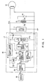
- FIG. 1 A warning and stopping circuit of an industrial engine according to the present invention is illustrated in FIG. 1, in which reference numeral 11 designates an ignition circuit.
- An ignition voltage VIG is supplied from a magneto 12 to the ignition circuit 11.
- the ignition circuit 11 is connected in parallel with a primary coil 13a of an ignition coil 13.
- a secondary coil 13b of the ignition coil 13 is connected to an ignition plug 14.
- a warning and stopping circuit 15 is connected to the primary coil 13a of the ignition coil 13 in parallel with the ignition circuit 11.
- the warning and stopping circuit 15 is connected to a sensor 16 for sensing a lack of a working fluid such as an engine oil.
- the warning and stopping circuit 15 includes a warning lamp lighting and engine stopping controller 17 which is connected to the magneto 12.
- the warning and stopping circuit 15 is further provided with a steady power supply circuit 18, a sensor control unit 19, a switching signal generator 20, a signal delaying unit 21 and a timer 22.
- the controller 17 includes a mode switching unit 17a and a lighting and stopping unit 17b connected to the mode switching unit 17a.
- the lighting and stopping unit 17b is connected in parallel with the ignition circuit 11, and an LED 17c as a warning lamp is connected to the lighting and stopping unit 17b.
- the steady power supply circuit 18 rectifies and smoothes the ignition voltage VIG and supplies a rectified and smoothed voltage to each part of the warning and stopping circuit 15.
- the timer 22 starts time delay operation. After the time delay operation is completed, a high level output signal TS is outputted from the timer 22 to the switching signal generator 20.
- the sensor control unit 19 outputs a high level detection signal RL, for example, according to a detection signal DS from the sensor 16 when the oil level becomes below a lower limit level.
- the detection signal RL is inputted to the switching signal generator 20 and the signal delaying unit 21. In response to the detection signal RL the switching signal generator 20 outputs a switching signal S to the mode switching unit 17a of the controller 17.
- the detection signal RL is delayed by the signal delaying unit 21 and outputted as an actuating signal T to the lighting and stopping unit 17b.
- the lighting and stopping unit 17b includes two operating modes: that is, a warning mode by lighting the LED 17c and an engine stopping mode by short-circuiting the ignition voltage VIG of the magneto 12.
- a warning mode by lighting the LED 17c
- an engine stopping mode by short-circuiting the ignition voltage VIG of the magneto 12.
- the LED lighting mode of the lighting and stopping unit 17b is established by the mode switching unit 17a.
- the ignition voltage VIG is supplied from the magneto 12, and then when an engine speed reaches a predetermined speed, voltage rectified and smoothed by the steady power supply circuit 18 reaches a predetermined level and is stabilized over the is predetermined level. Consequently, the timer 22 starts the time delay operation in which the timer 22 starts to count the time and produces the high level output signal TS after the predetermined time is lapsed.
- the sensor control unit 19 When the sensor 16 detects a lack of an engine oil, for example, the detection signal DS is provided to the sensor control unit 19. Consequently, the sensor control unit 19 outputs a high level detection signal RL to both the switching signal generator 20 and the signal delaying unit 21 as illustrated by the broken line in FIG. 2.
- the switching signal generator 20 When the high level detection signal RL is provided to the switching signal generator 20 before the timer 22 outputs the high level output signal TS to the switching signal generator 20, the switching signal generator 20 outputs a switching signal S to the mode switching unit 17a so that the mode switching unit 17a outputs the mode switching signal MS to the lighting and stopping unit 17b to establish an engine stopping mode of the lighting and stopping unit 17b as also shown by the broken line in FIG. 2.
- the actuating signal T which is provided from the signal delaying unit 21 to the lighting and stopping unit 17b is delayed by a delay time Td sufficient to establish the engine stopping mode as also shown by the broken line.
- the ignition voltage VIG is shorted by the lighting and stopping unit 17b, so that the primary coil 13a of the ignition coil 13 drops below an ignition limit voltage.
- the engine is positively stopped without any malfunction.
- the sensor control unit 19 when the engine oil reduces below a predetermined lower limit oil levels after the switching signal generator 20 receives, the high level output signal TS from the timer 22, the sensor control unit 19 outputs a high level detection signal RL to the switching signal generator 20.
- the switching signal generator 20 provides a switching signal S to the mode switching unit 17a, which accordingly outputs a mode switching signal MS to the lighting and stopping unit 17b to switch the lighting and stopping unit 17b to the LED lighting mode.
- the detection signal RL from the sensor control unit 19 is inputted to the lighting and stopping unit 17b through the signal delaying unit 21 with the delay time Td.
- the LED 17c positively lights without any malfunction.
- the lighting and stopping unit 17b shifts the timing to short-circuit the ignition voltage VIG from an arc discharge region TIGC in an ignition region of the ignition voltage VIG to a glow discharge region TIGL following the arc discharge region as shown in FIG. 3.
- the arc discharge region TIGC and the glow discharge region TIGL are due to capacitive and inductive components, respectively.
- the ignition energy loss due to the lighting of the LED 17c is fairly small, and hence the lighting of the LED 17c does not deteriorate ignition performance of the ignition plug 14. Therefore, the LED 17c lights without stopping the engine when the engine oil decreases below the lower limit level after the timer 22 outputs the high level output signal TS.
- the warning and stopping circuit 15 When the predetermined lower limit oil level is set with a sufficient margin of safety, the warning and stopping circuit 15 enables the work using the engine to continue for a while.
- the warning and stopping circuit 15 provides less expensive construction than the conventional warning equipment.
- the warning and stopping circuit 15 stops the engine when it is detected within a predetermined time interval after the engine starts that the amount of the working fluid is below a safety margin. Thus, the engine is stopped at once in the case where the engine is restarted without supplying the working fluid in spite of the warning being given. This prevents engine troubles from taking place.
- the working fluid may be a cooling water.
- the warning may be given by an electrical load, such as an hour meter, in place of the LED 17c.
- FIG. 4 A modified form of the warning and stopping circuit of FIG. 3 is illustrated in FIG. 4.
- a detection signal RL is inputted from the sensor control unit 19 to the timer 22 as well as the switching signal generator 20 and the signal delaying unit 21.
- the switching signal generator 20 In response to the detection signal RL, the switching signal generator 20 outputs a high level switching signal S to the mode switching unit 17a before the switching signal generator 20 receives a high, level output signal TS from the timer 22. As a result, the mode switching unit 17a outputs a mode switching signal MS to switch the lighting and stopping unit 17b to the LED lighting mode. In this mode, the lighting and stopping unit 17b receives an actuating signal T from the signal delaying unit 21 with a delay time Td and then lights the LED 17c.
- the lighting and stopping unit 17b shifts the timing to short the ignition voltage VIG from an arc discharge region TIGC in an ignition region of the ignition plug 14 to a glow discharge region TIGL to light the LED 17c as shown in FIG. 3.
- the timer 22 outputs the high level output signal TS sto the switching signal generator 20 in a predetermined interval after receiving the detection signal RL. According to the output signal TS, the switching signal generator 20 inverts the switching signal S to a low level. With the inverted switching signal S, the mode switching unit 17a switches the lighting and stopping unit 17b from the LED lighting mode to the engine stopping mode. Thus, the ignition voltage VIG is short-circuited to drop the primary coil 13a below an ignition voltage level, so that the engine is stopped.
- the engine is always stopped in a predetermined time after a lack of a working fluid is detected.
- the warning and stopping circuit 25 positively prevents any abnormality of the engine from taking place.
- FIG. 6 shows one example of a detailed circuitry of the ignition circuit 11 and the mode switching unit 17a and the lighting and stopping unit 17b of the controller 17 in FIGS. 1 and 4.
- a low level signal for the stopping mode is applied to a base of a transistor TR in the mode switching unit 17a and a high level signal from the sensor control unit 19 is applied to a gate of a thyristor SCR2 in the lighting and stopping unit 17b
- a high level signal is applied to a gate of a thyristor SCR1 in the lighting and stopping unit 17b at a timing of the arc discharge region so as to enable the engine to stop as mentioned above.
- the LED 17c is lighted to indicate a lack of the working fluid.
Landscapes
- Engineering & Computer Science (AREA)
- Chemical & Material Sciences (AREA)
- Combustion & Propulsion (AREA)
- Mechanical Engineering (AREA)
- General Engineering & Computer Science (AREA)
- Ignition Installations For Internal Combustion Engines (AREA)
Applications Claiming Priority (4)
| Application Number | Priority Date | Filing Date | Title |
|---|---|---|---|
| JP16482989A JP2816185B2 (ja) | 1989-06-26 | 1989-06-26 | エンジンの警告及び停止装置 |
| JP16483089A JP2816186B2 (ja) | 1989-06-26 | 1989-06-26 | エンジンの警告及び停止装置 |
| JP164829/89 | 1989-06-26 | ||
| JP164830/89 | 1989-06-26 |
Publications (3)
| Publication Number | Publication Date |
|---|---|
| EP0405415A2 true EP0405415A2 (fr) | 1991-01-02 |
| EP0405415A3 EP0405415A3 (en) | 1991-06-12 |
| EP0405415B1 EP0405415B1 (fr) | 1995-09-13 |
Family
ID=26489784
Family Applications (1)
| Application Number | Title | Priority Date | Filing Date |
|---|---|---|---|
| EP90112062A Expired - Lifetime EP0405415B1 (fr) | 1989-06-26 | 1990-06-25 | Système de surveillance d'un moteur |
Country Status (3)
| Country | Link |
|---|---|
| US (1) | US5117218A (fr) |
| EP (1) | EP0405415B1 (fr) |
| DE (1) | DE69022302T2 (fr) |
Families Citing this family (7)
| Publication number | Priority date | Publication date | Assignee | Title |
|---|---|---|---|---|
| EP0725738B1 (fr) * | 1992-04-28 | 1999-08-18 | Dynamic Controls Limited | Dispositif de commande destine a des vehicules a propulsion electrique |
| JP3145501B2 (ja) * | 1992-09-21 | 2001-03-12 | 富士重工業株式会社 | エンジン停止装置 |
| KR100551306B1 (ko) * | 2003-12-30 | 2006-02-10 | 현대자동차주식회사 | 아이들 스톱 & 고 시스템 제어방법 |
| DE102004021394B4 (de) | 2004-04-30 | 2006-09-28 | Wacker Construction Equipment Ag | Ölstandsüberwachungssystem für Verbrennungsmotor |
| US7475665B2 (en) * | 2006-01-17 | 2009-01-13 | Wacker Neuson Corporation | Capacitance-based fluid level sensor |
| JP4934327B2 (ja) * | 2006-02-09 | 2012-05-16 | 本田技研工業株式会社 | 汎用エンジンのオイルレベル低下判断装置 |
| DE102010010749B4 (de) * | 2010-03-09 | 2016-12-22 | Wacker Neuson Produktion GmbH & Co. KG | Antriebssystem mit Vorrichtung zur Unterbrechung des Betriebs bei drohendem Betriebsstoffmangel sowie Arbeitsgerät und Verfahren |
Family Cites Families (4)
| Publication number | Priority date | Publication date | Assignee | Title |
|---|---|---|---|---|
| US3886518A (en) * | 1974-01-04 | 1975-05-27 | Ford Motor Co | Critical liquid-level warning circuit |
| US4933852A (en) * | 1979-08-22 | 1990-06-12 | Lemelson Jerome H | Machine operation indicating system and method |
| JPS6226379A (ja) * | 1985-07-29 | 1987-02-04 | Kawasaki Heavy Ind Ltd | エンジンの自動停止装置 |
| JPS62121833A (ja) * | 1985-11-20 | 1987-06-03 | Sanshin Ind Co Ltd | エンジンの異常警告装置 |
-
1990
- 1990-06-21 US US07/541,764 patent/US5117218A/en not_active Expired - Fee Related
- 1990-06-25 DE DE69022302T patent/DE69022302T2/de not_active Expired - Fee Related
- 1990-06-25 EP EP90112062A patent/EP0405415B1/fr not_active Expired - Lifetime
Also Published As
| Publication number | Publication date |
|---|---|
| DE69022302D1 (de) | 1995-10-19 |
| US5117218A (en) | 1992-05-26 |
| DE69022302T2 (de) | 1996-04-18 |
| EP0405415A3 (en) | 1991-06-12 |
| EP0405415B1 (fr) | 1995-09-13 |
Similar Documents
| Publication | Publication Date | Title |
|---|---|---|
| US5068570A (en) | Lamp lighting circuit with an overload protection capability | |
| US6222719B1 (en) | Ignition boost and rectification flame detection circuit | |
| JP2587720B2 (ja) | 車輌用放電灯の点灯回路 | |
| US4456855A (en) | Intensity regulator, especially a light regulator | |
| KR100282995B1 (ko) | 차량용 발전기의 제어장치 | |
| EP0297584A2 (fr) | Système d'allumage pour moteur à combustion interne | |
| EP0724321B1 (fr) | Appareil de commande d'un alternateur de véhicule à moteur | |
| US4349854A (en) | Power generation control system for vehicle generator | |
| US5107094A (en) | Vehicle heating system with failure detection means | |
| EP0405415B1 (fr) | Système de surveillance d'un moteur | |
| MXPA04002360A (es) | Aparato y metodo para la deteccion transitoria de la condicion final de la vida de una lampara. | |
| US4854292A (en) | Ignition system for internal combustion engine | |
| US4306184A (en) | Generation control appparatus for vehicle generators | |
| JPS57110084A (en) | Transistor inverter | |
| US4329628A (en) | Relaxation oscillator type spark generator | |
| US5076250A (en) | Engine shut-down device | |
| US4231345A (en) | Apparatus for controlling an electrical switching element in internal combustion engines | |
| JPH0810969B2 (ja) | 車両用交流発電機の制御装置 | |
| EP0371827A2 (fr) | Système d'allumage de secours pour véhicules à moteur | |
| US5027772A (en) | Engine knock control system | |
| JPWO2001095455A1 (ja) | ランプ点灯及びバッテリ充電制御装置 | |
| US4153031A (en) | Apparatus for preventing sparks in the ignition system of an engine while the engine is at rest | |
| JPS6026175A (ja) | 内燃機関停止装置 | |
| US4965494A (en) | Capacitor charging circuit for timing light power source | |
| JP2816185B2 (ja) | エンジンの警告及び停止装置 |
Legal Events
| Date | Code | Title | Description |
|---|---|---|---|
| PUAI | Public reference made under article 153(3) epc to a published international application that has entered the european phase |
Free format text: ORIGINAL CODE: 0009012 |
|
| 17P | Request for examination filed |
Effective date: 19900625 |
|
| AK | Designated contracting states |
Kind code of ref document: A2 Designated state(s): DE FR GB |
|
| PUAL | Search report despatched |
Free format text: ORIGINAL CODE: 0009013 |
|
| AK | Designated contracting states |
Kind code of ref document: A3 Designated state(s): DE FR GB |
|
| 17Q | First examination report despatched |
Effective date: 19930917 |
|
| GRAA | (expected) grant |
Free format text: ORIGINAL CODE: 0009210 |
|
| AK | Designated contracting states |
Kind code of ref document: B1 Designated state(s): DE FR GB |
|
| REF | Corresponds to: |
Ref document number: 69022302 Country of ref document: DE Date of ref document: 19951019 |
|
| ET | Fr: translation filed | ||
| PLBE | No opposition filed within time limit |
Free format text: ORIGINAL CODE: 0009261 |
|
| STAA | Information on the status of an ep patent application or granted ep patent |
Free format text: STATUS: NO OPPOSITION FILED WITHIN TIME LIMIT |
|
| 26N | No opposition filed | ||
| PGFP | Annual fee paid to national office [announced via postgrant information from national office to epo] |
Ref country code: GB Payment date: 19970612 Year of fee payment: 8 |
|
| PGFP | Annual fee paid to national office [announced via postgrant information from national office to epo] |
Ref country code: FR Payment date: 19970626 Year of fee payment: 8 |
|
| PGFP | Annual fee paid to national office [announced via postgrant information from national office to epo] |
Ref country code: DE Payment date: 19970704 Year of fee payment: 8 |
|
| PG25 | Lapsed in a contracting state [announced via postgrant information from national office to epo] |
Ref country code: GB Free format text: LAPSE BECAUSE OF NON-PAYMENT OF DUE FEES Effective date: 19980625 |
|
| GBPC | Gb: european patent ceased through non-payment of renewal fee |
Effective date: 19980625 |
|
| PG25 | Lapsed in a contracting state [announced via postgrant information from national office to epo] |
Ref country code: FR Free format text: LAPSE BECAUSE OF NON-PAYMENT OF DUE FEES Effective date: 19990226 |
|
| PG25 | Lapsed in a contracting state [announced via postgrant information from national office to epo] |
Ref country code: DE Free format text: LAPSE BECAUSE OF NON-PAYMENT OF DUE FEES Effective date: 19990401 |
|
| REG | Reference to a national code |
Ref country code: FR Ref legal event code: ST |