EP0405716A2 - Câble bobinable à couple balancé et méthode de fabrication - Google Patents
Câble bobinable à couple balancé et méthode de fabrication Download PDFInfo
- Publication number
- EP0405716A2 EP0405716A2 EP90304254A EP90304254A EP0405716A2 EP 0405716 A2 EP0405716 A2 EP 0405716A2 EP 90304254 A EP90304254 A EP 90304254A EP 90304254 A EP90304254 A EP 90304254A EP 0405716 A2 EP0405716 A2 EP 0405716A2
- Authority
- EP
- European Patent Office
- Prior art keywords
- cable
- armor
- layer
- wires
- tape
- Prior art date
- Legal status (The legal status is an assumption and is not a legal conclusion. Google has not performed a legal analysis and makes no representation as to the accuracy of the status listed.)
- Granted
Links
- 238000004519 manufacturing process Methods 0.000 title claims description 5
- 238000000034 method Methods 0.000 title claims 3
- 238000005452 bending Methods 0.000 claims abstract description 7
- 229920000728 polyester Polymers 0.000 claims abstract description 4
- 239000013307 optical fiber Substances 0.000 claims description 3
- 239000011521 glass Substances 0.000 claims description 2
- 239000000463 material Substances 0.000 claims description 2
- 239000000126 substance Substances 0.000 claims description 2
- 230000005540 biological transmission Effects 0.000 claims 1
- 230000001747 exhibiting effect Effects 0.000 abstract description 3
- 238000009434 installation Methods 0.000 description 8
- 230000009467 reduction Effects 0.000 description 8
- 239000011435 rock Substances 0.000 description 8
- XLYOFNOQVPJJNP-UHFFFAOYSA-N water Substances O XLYOFNOQVPJJNP-UHFFFAOYSA-N 0.000 description 5
- 229910001335 Galvanized steel Inorganic materials 0.000 description 4
- 239000008397 galvanized steel Substances 0.000 description 4
- 239000004698 Polyethylene Substances 0.000 description 3
- -1 polyethylene Polymers 0.000 description 3
- 229920000573 polyethylene Polymers 0.000 description 3
- RYGMFSIKBFXOCR-UHFFFAOYSA-N Copper Chemical compound [Cu] RYGMFSIKBFXOCR-UHFFFAOYSA-N 0.000 description 2
- 229910000831 Steel Inorganic materials 0.000 description 2
- 238000005299 abrasion Methods 0.000 description 2
- 238000004458 analytical method Methods 0.000 description 2
- 238000004891 communication Methods 0.000 description 2
- 229910052802 copper Inorganic materials 0.000 description 2
- 239000010949 copper Substances 0.000 description 2
- 229920001903 high density polyethylene Polymers 0.000 description 2
- 239000004700 high-density polyethylene Substances 0.000 description 2
- 238000009413 insulation Methods 0.000 description 2
- 229920001179 medium density polyethylene Polymers 0.000 description 2
- 239000004701 medium-density polyethylene Substances 0.000 description 2
- 239000010959 steel Substances 0.000 description 2
- 230000007704 transition Effects 0.000 description 2
- 238000004804 winding Methods 0.000 description 2
- 241000276489 Merlangius merlangus Species 0.000 description 1
- 239000004677 Nylon Substances 0.000 description 1
- 230000002411 adverse Effects 0.000 description 1
- 239000010426 asphalt Substances 0.000 description 1
- 230000000295 complement effect Effects 0.000 description 1
- 230000006835 compression Effects 0.000 description 1
- 238000007906 compression Methods 0.000 description 1
- 229920001577 copolymer Polymers 0.000 description 1
- 230000007797 corrosion Effects 0.000 description 1
- 238000005260 corrosion Methods 0.000 description 1
- 238000010586 diagram Methods 0.000 description 1
- 238000004134 energy conservation Methods 0.000 description 1
- 238000001125 extrusion Methods 0.000 description 1
- 239000000835 fiber Substances 0.000 description 1
- 229920001778 nylon Polymers 0.000 description 1
- 230000035515 penetration Effects 0.000 description 1
- 229920002635 polyurethane Polymers 0.000 description 1
- 239000004814 polyurethane Substances 0.000 description 1
- 239000011271 tar pitch Substances 0.000 description 1
- 239000003643 water by type Substances 0.000 description 1
Images

Classifications
-
- G—PHYSICS
- G02—OPTICS
- G02B—OPTICAL ELEMENTS, SYSTEMS OR APPARATUS
- G02B6/00—Light guides; Structural details of arrangements comprising light guides and other optical elements, e.g. couplings
- G02B6/44—Mechanical structures for providing tensile strength and external protection for fibres, e.g. optical transmission cables
- G02B6/4401—Optical cables
- G02B6/4429—Means specially adapted for strengthening or protecting the cables
- G02B6/443—Protective covering
- G02B6/4432—Protective covering with fibre reinforcements
-
- G—PHYSICS
- G02—OPTICS
- G02B—OPTICAL ELEMENTS, SYSTEMS OR APPARATUS
- G02B6/00—Light guides; Structural details of arrangements comprising light guides and other optical elements, e.g. couplings
- G02B6/44—Mechanical structures for providing tensile strength and external protection for fibres, e.g. optical transmission cables
- G02B6/4401—Optical cables
- G02B6/4415—Cables for special applications
- G02B6/4416—Heterogeneous cables
-
- G—PHYSICS
- G02—OPTICS
- G02B—OPTICAL ELEMENTS, SYSTEMS OR APPARATUS
- G02B6/00—Light guides; Structural details of arrangements comprising light guides and other optical elements, e.g. couplings
- G02B6/44—Mechanical structures for providing tensile strength and external protection for fibres, e.g. optical transmission cables
- G02B6/4401—Optical cables
- G02B6/4415—Cables for special applications
- G02B6/4427—Pressure resistant cables, e.g. undersea cables
-
- G—PHYSICS
- G02—OPTICS
- G02B—OPTICAL ELEMENTS, SYSTEMS OR APPARATUS
- G02B6/00—Light guides; Structural details of arrangements comprising light guides and other optical elements, e.g. couplings
- G02B6/44—Mechanical structures for providing tensile strength and external protection for fibres, e.g. optical transmission cables
- G02B6/4401—Optical cables
- G02B6/4429—Means specially adapted for strengthening or protecting the cables
-
- H—ELECTRICITY
- H01—ELECTRIC ELEMENTS
- H01B—CABLES; CONDUCTORS; INSULATORS; SELECTION OF MATERIALS FOR THEIR CONDUCTIVE, INSULATING OR DIELECTRIC PROPERTIES
- H01B7/00—Insulated conductors or cables characterised by their form
- H01B7/14—Submarine cables
Definitions
- This invention relates to design of armored undersea telecommunications cable systems; and particularly to achieving a torque-balanced cable system which exhibits substantial freedom from kinking or looping during storage and coiling.
- Armor usually is provided by one or more lays of galvanized steel wires around the core and its jacketing.
- torque balance is to be included in any segment of an undersea cable system, it is desirable that the entire system be torque- balanced, since otherwise transition cables are required to couple one cable type to another. By using a torque-balanced system, however, no transition cables are needed; and the costs and complexities of cable system installation are reduced.
- one object of the invention is to provide a torque- balanced undersea cable which can be coiled to small diameters.
- Another object of the invention is to achieve such a cable while retaining the desirable properties which characterize torque-balanced cables.
- An additional object of the invention is to provide a comprehensive undersea cable system whose structure is torque-balanced throughout the installation, from open ocean depths to shore linkages in relatively shallow water.
- This invention in its broadest application teaches a class of torsionally balanced submarine cables which are highly coilable without exhibiting the undesirable tendencies of looping and kinking of its predecessors.
- the invention may be applied to telecommunications cables, as described below; or may be applied to other types of cable, such as power cables.
- Coilability is achieved in part, pursuant to the invention, by controlling the cable's torsional stiffness (JG) to bending stiffness ratio (EI) to within certain bounds heretofore not recognized.
- JG torsional stiffness
- EI bending stiffness ratio
- the use of glass-reinforced polyester tape between and over the armor wires has been found to facilitate movement of the armor wire during coiling, and thus facilitates the coiling.
- the tape also acts as a bedding.
- maintaining to within prescribed bounds the torsional stiffness to cable weight ratio can also contribute to achieving a coilable torque-balanced cable.
- Deep and shallow water illustrative embodiments hereinafter described, may be combined pursuant to the invention to create a torque-balanced undersea communication cable system.
- Weight of the cable design is significant because weight affects the coilability. The heavier the cable, the less is the likelihood that the cable will lop or become unstable.
- the teachings of the present invention are substantially independent of cable diameter; and are generic for cables experiencing strains in the elastic range.
- T in equation 1 may be calculated by solving for T the following expression: where W is the cable weight per unit length; H is the height or length of the catenary (for example, from a cable ship's deck to the floor of the coiling tank); and T is the cable tension the point where the cable touches down on the coiling tank floor.
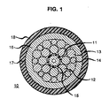
- the cable design in this example consists of a deep water core 10, depicted in FIG. 1, which is conventional. Other core structures may be used.
- the core 10 includes a buffered communications optical fiber member denoted 11.
- the fiber member's diameter is approximately 0.065 inches.
- a region of steel wires is placed, which consist in this example of a cluster 12 of eight wires of 0.041 inch diameter, a second cluster 13 of eight wires of 0.039 inch diameter, and a third cluster 14 of eight wires of 0.030 diameter. These are applied with a 6-inch left-hand overlay.
- An encapsulate of polyurethane, denoted 15, is applied around the member 11 and between the wires of the clusters 12, 13, 14.
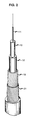
- the armor layers next to be applied comprise a first layer 19 of sixteen galvanized steel wires, preformed to form helices prior to their being assembled over the jacket 18.
- the percent preform is controlled.
- the inside diameter of the preform of the first armor layer 19 is 0.510 inches.
- the percent preform is 0.420/0.510, or 82 percent.
- the significance of a preform of 82 percent is that an average clearance of approximately 0.045 inches is afforded between the core surface and the preform inside diameter, which is advantageous because it reduces the tendency of the armor wires to embed into the insulation during coiling. Further, because the armor wires are formed, the wires have more freedom to move and remain strain-free.
- a 10-degree right-hand lay angle is imparted to the wires of the first armor layer 19.
- the outside diameter of the first layer is 0.60 inches.
- a 0.006 inch thick by 0.5 inch-wide glass reinforced polyester tape layer 20 is wrapped around the first layer 19 of armor wires, using a 1.91 inch left-hand lay, to a 0.612 inch outside diameter.
- the function of tape layer 20 is to aid movement of armor wire during coiling, and to hold armor wires during the cable's manufacture.
- a second layer 21 consisting of 36 galvanized steel wires each being 0.052 inch in outside diameter, is applied using a 10 degree lay angle and a left-hand lay to an outside diameter of of 0.716 inches.
- a further application of glass-reinforced tape (not shown) is placed over the second armor wire layer 21. This second tape layer functions to also hold the armor wires.
- a high-density polyethylene outer jacket 24 is extruded over the final tape.
- the final outside diameter of the cable of the instant embodiment is 0.910 inches.
- An open lay is used in applying the tape layers, to provide adequate adhesion of the steel wires, the tape and the outer jacket 18. That is, the tape is applied with a gap 23, between adjacent turns as shown in FIG. 4. If no gap were provided, the armor wires would be covered completely with the tape.
- the gap 23 allows the polyethylene substance of the final jacket to become extended to the region between the tape and the valleys formed by adjacent armor wires., during the extrusion of the polyethylene jacket 24. The result is a firm and strong bond between the jacket 24 and the layers 19, 21 of armor wires.
- the above-described design exhibits, pursuant to the invention, a torsional stiffness to bending stiffness ratio of approximately 2.34.
- the ratio is achieved by reducing the lay angles of both armor layers to approximately 10 degrees. By so reducing the lay angles, the torsional stiffness is reduced significantly.
- the calculated torsional stiffness (JG) of the cable of this example is 16,828 inch-squared pounds.
- the bending stiffness (EI) is 7,166 inch-squared pounds.
- the theoretical JG/EI ratio is 2.34.
- the measured JG/EI ratio of the described design is in a range of 2.37 to 2.47. Coiling diameters of as low as 4.5 feet have been achieved with cables designed and manufactured pursuant to the inventive teachings.
- Prior art torque-balanced cables with similar configurations exhibit an inability to be coiled. These typically have a JG/EI ratio in the vicinity of 10.
- the reducing of the JG/EI ratio is material to realizing the cable coilability.
- the JG/EI ratio which achieves substantial coilability results in accordance with the invention thus is seen to be approximately 3.00.
- a relatively small reduction in the per-cent of armor coverage has been found to make an unexpectedly large additional contribution to cable coilability.
- armored cables are designed with armor wire coverage in the range of 95-98 percent. In the cable as taught in the present invention, however, the coverage is reduced, but only relatively slightly. For example, in the cable of example 1 above, the coverage of layer 19 is 92 percent, and that of. No significant reduction in the protection afforded to the core by the armor is attendant the coverage 10 reduction.
- the cable of this inventive example allows the inner polyethylene insulation of the core 10 to experience relatively more radially compression during coiling. Thus, more coil twist per unit length can take place before lockup or binding occurs.
- the preforming, the relatively low lay angles of the armor wires, and the tape applications all play a vital role in the design.
- One of the invention's objects is to provide a cable system including a deep water component and a shore link, both being torque-balanced.
- the embodiment described above fulfills the deep water requirement.
- the cable structure next to be described is a useful shore link exhibiting torque-balance and high resistance to the damage sources (commercial fishing, etc.) common in shallower waters.
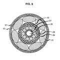
- the cable fits the design requirement for the shore link. It consists of a trunk core 26 of 0.250 inch outside diameter, similar in structure to that of FIG. 1, over which is placed a belt 27 of medium density polyethylene, to an outside diameter of 0.490 inch. Then, a first layer 28 of ten galvanized steel wires each having a diameter of 0.191 inch (190 ksi) are stranded, using a 19.1 degree lay angle and a right-hand lay. The resulting outside diameter is 0.872 inch.
- a second layer 29 of armor consisting of thirty 0.087 inch (190 ksi) galvanized wires are stranded over the first layer 28, using a 22 degree lay angle and a left-hand lay to an outside diameter of 1.05 inches.
- a high density polyethylene jacket 30 is extruded, to an outside diameter of 1.29 inches.
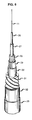
- a layer 31 of seven rock armor wires each having a diameter of 0.38 inch (50 ksi) and a tar coat are stranded over the jacket 30, using a lay angle of 57 degrees and a left-hand lay, to a 2.06 inches outside diameter.
- the function of the rock armor is to provide weight to hold the cable in position; to provide resistance to penetration and crushing; and to provide abrasion resistance to wave motion.
- Two servings 32, 33 of nylon yarn, advantageously Hyten type 102, JEA 80, are now applied over the rock armor layer 31.
- the first layer 32 contains 37 ends, and the second layer 33 contains 38 ends. Both layers use a 5.1 inches lay-length and a right-hand lay.
- the function of layers 32, 33 is to hold the rock armor in position during the installation of the rock armor lays.
- the layers also provide corrosion and abrasion protection.
- An asphalt layer of tar pitch (not shown) next is applied under, between, and over the yarn ends.
- the diameter of the cable 25 measured over the two yarn servings is, respectively, 2.20 inches and 2.34 inches.
- chalk whiting is applied over the entire cable exterior, to prevent the cable from sticking to its adjacent portions when reeled or in a coiling pan or tank, or during manufacture.
- JG/EI torsional stiffness to bending stiffness ratio
- the rock armor wires of the layer 31 act like a spring in this design. During coiling, the rock armor wires unlay and are not restrained.
Landscapes
- Physics & Mathematics (AREA)
- General Physics & Mathematics (AREA)
- Optics & Photonics (AREA)
- Insulated Conductors (AREA)
- Communication Cables (AREA)
- Manufacturing Of Electric Cables (AREA)
Applications Claiming Priority (2)
| Application Number | Priority Date | Filing Date | Title |
|---|---|---|---|
| US373967 | 1989-06-29 | ||
| US07/373,967 US4979795A (en) | 1989-06-29 | 1989-06-29 | Coilable torque-balanced cable and method of manufacture |
Publications (3)
| Publication Number | Publication Date |
|---|---|
| EP0405716A2 true EP0405716A2 (fr) | 1991-01-02 |
| EP0405716A3 EP0405716A3 (en) | 1992-03-18 |
| EP0405716B1 EP0405716B1 (fr) | 1997-07-09 |
Family
ID=23474680
Family Applications (1)
| Application Number | Title | Priority Date | Filing Date |
|---|---|---|---|
| EP90304254A Expired - Lifetime EP0405716B1 (fr) | 1989-06-29 | 1990-04-20 | Câble bobinable à couple balancé |
Country Status (4)
| Country | Link |
|---|---|
| US (1) | US4979795A (fr) |
| EP (1) | EP0405716B1 (fr) |
| JP (1) | JPH0770258B2 (fr) |
| AU (1) | AU610458B2 (fr) |
Cited By (6)
| Publication number | Priority date | Publication date | Assignee | Title |
|---|---|---|---|---|
| EP0816885A3 (fr) * | 1996-06-18 | 1998-09-16 | Brugg Telecom AG | Câble optique avec armatureet son utilisation |
| FR2769749A1 (fr) * | 1997-10-13 | 1999-04-16 | Inst Francais Du Petrole | Tige renforcee en materiau composite |
| EP1717620A1 (fr) * | 2005-04-27 | 2006-11-02 | Run Chi Hsu | Câble optique anti-torsion |
| GB2448778A (en) * | 2007-05-18 | 2008-10-29 | Draka Uk Ltd | Fire-resistant Cable |
| EP3918617A1 (fr) * | 2019-01-28 | 2021-12-08 | RWE Renewables GmbH | Câble sous-marin offshore pour parc éolien offshore |
| WO2024134122A1 (fr) * | 2022-12-22 | 2024-06-27 | Acome | Câble blindé électrique |
Families Citing this family (41)
| Publication number | Priority date | Publication date | Assignee | Title |
|---|---|---|---|---|
| JP3176390B2 (ja) * | 1990-06-13 | 2001-06-18 | 宇部日東化成株式会社 | 強化プラスチック製鎧装ケーブルの製造方法 |
| FR2664987B1 (fr) * | 1990-07-19 | 1993-07-16 | Alcatel Cable | Cable sous-marin de telecommunications a fibres optiques sous tube. |
| US5125062A (en) * | 1990-07-19 | 1992-06-23 | Alcatel Cable | Undersea telecommunications cable having optical fibers |
| JP2852847B2 (ja) * | 1993-06-04 | 1999-02-03 | 東京特殊電線株式会社 | 同軸ケーブル |
| US5539851A (en) * | 1995-04-17 | 1996-07-23 | Taylor; John A. | Hybrid optical fiber/copper coaxial data transmission cable |
| US6463198B1 (en) * | 2000-03-30 | 2002-10-08 | Corning Cable Systems Llc | Micro composite fiber optic/electrical cables |
| US20030032146A1 (en) * | 2001-07-10 | 2003-02-13 | Dwulet Francis Edward | Enzyme/tag binding and detection system |
| US7184364B2 (en) * | 2002-10-29 | 2007-02-27 | Geospace Engineering Resources International, Lp | Armored seabed laid seismic cable and method and apparatus for manufacturing same |
| US7254302B2 (en) * | 2002-12-19 | 2007-08-07 | Corning Cable Systems, Llc. | Optical tube assembly having a dry insert and methods of making the same |
| US7336873B2 (en) | 2002-12-19 | 2008-02-26 | Corning Cable Systems, Llc. | Optical tube assembly having a dry insert and methods of making the same |
| US7415181B2 (en) * | 2005-07-29 | 2008-08-19 | Corning Cable Systems Llc | Fiber optic cables and assemblies for fiber to the subscriber applications |
| US7277615B2 (en) * | 2002-12-19 | 2007-10-02 | Corning Cable Systems, Llc. | Fiber optic cable having a dry insert and methods of making the same |
| US7471862B2 (en) | 2002-12-19 | 2008-12-30 | Corning Cable Systems, Llc | Dry fiber optic cables and assemblies |
| US20090190890A1 (en) * | 2002-12-19 | 2009-07-30 | Freeland Riley S | Fiber optic cable having a dry insert and methods of making the same |
| US6970629B2 (en) * | 2002-12-19 | 2005-11-29 | Corning Cable Systems Llc | Optical tube assembly having a dry insert and methods of making the same |
| US8413723B2 (en) | 2006-01-12 | 2013-04-09 | Schlumberger Technology Corporation | Methods of using enhanced wellbore electrical cables |
| US7402753B2 (en) | 2005-01-12 | 2008-07-22 | Schlumberger Technology Corporation | Enhanced electrical cables |
| US7170007B2 (en) * | 2005-01-12 | 2007-01-30 | Schlumburger Technology Corp. | Enhanced electrical cables |
| US20060239624A1 (en) * | 2005-04-20 | 2006-10-26 | Hsu Run C | Anti-twisting optical fiber cable as protected by left-turn and right-turn spring coils |
| US7188406B2 (en) * | 2005-04-29 | 2007-03-13 | Schlumberger Technology Corp. | Methods of manufacturing enhanced electrical cables |
| US20070230879A1 (en) * | 2006-03-31 | 2007-10-04 | Mcalpine Warren W | Armored fiber optic cable having a centering element and methods of making |
| US8069879B2 (en) * | 2006-09-15 | 2011-12-06 | Schlumberger Technology Corporation | Hydrocarbon application hose |
| US9158015B2 (en) * | 2007-10-04 | 2015-10-13 | Westerngeco L.L.C. | Seismic streamer platform |
| US8697992B2 (en) * | 2008-02-01 | 2014-04-15 | Schlumberger Technology Corporation | Extended length cable assembly for a hydrocarbon well application |
| US7912333B2 (en) * | 2008-02-05 | 2011-03-22 | Schlumberger Technology Corporation | Dual conductor fiber optic cable |
| US11387014B2 (en) | 2009-04-17 | 2022-07-12 | Schlumberger Technology Corporation | Torque-balanced, gas-sealed wireline cables |
| US9412492B2 (en) | 2009-04-17 | 2016-08-09 | Schlumberger Technology Corporation | Torque-balanced, gas-sealed wireline cables |
| WO2011037974A2 (fr) | 2009-09-22 | 2011-03-31 | Schlumberger Canada Limited | Câble métallique destiné à l'utilisation avec des ensembles tracteurs de forage |
| US12163394B2 (en) | 2009-04-17 | 2024-12-10 | Schlumberger Technology Corporation | Reduced torque wireline cable |
| US20150155073A1 (en) * | 2010-06-09 | 2015-06-04 | Schlumberger Technology Corporation | Wireline Cables Not Requiring Seasoning |
| EP2769386A4 (fr) | 2011-10-17 | 2016-02-17 | Services Petroliers Schlumberger | Câble à double utilisation doté d'une encapsulation de fibre optique et destiné à être utilisé dans des opérations de puits de forage |
| WO2014004026A1 (fr) | 2012-06-28 | 2014-01-03 | Schlumberger Canada Limited | Câble optoélectrique à puissance élevée doté de multiples chemins d'alimentation et de télémétrie |
| US9605778B2 (en) * | 2013-08-02 | 2017-03-28 | Oceaneering International, Inc. | Extruded encapsulated fillers to provide crush protection |
| NO340781B1 (no) * | 2013-11-18 | 2017-06-19 | Nexans | Kabel for nedihullspumpe |
| CN104112509A (zh) * | 2014-07-18 | 2014-10-22 | 中天科技海缆有限公司 | 一种基于扭矩平衡设计的金属铠装电缆及其设计方法 |
| US11725468B2 (en) | 2015-01-26 | 2023-08-15 | Schlumberger Technology Corporation | Electrically conductive fiber optic slickline for coiled tubing operations |
| US11511085B2 (en) | 2015-11-18 | 2022-11-29 | Heraeus Deutschland GmbH & Co. KG | Torque coil and method |
| US10049789B2 (en) | 2016-06-09 | 2018-08-14 | Schlumberger Technology Corporation | Compression and stretch resistant components and cables for oilfield applications |
| US12436347B2 (en) | 2019-06-28 | 2025-10-07 | Schlumberger Technology Corporation | Stranded fiber-optic cable |
| MY201978A (en) * | 2019-09-13 | 2024-03-27 | Petroliam Nasional Berhad | Optical cable |
| US12321028B2 (en) | 2021-06-10 | 2025-06-03 | Schlumberger Technology Corporation | Electro-optical wireline cables |
Family Cites Families (10)
| Publication number | Priority date | Publication date | Assignee | Title |
|---|---|---|---|---|
| GB2010528B (en) * | 1977-12-16 | 1982-05-19 | Post Office | Underwater cables |
| IT1092793B (it) * | 1978-02-24 | 1985-07-12 | Pirelli | Cavo sottomarino perfezionato |
| GB1578439A (en) * | 1978-03-22 | 1980-11-05 | Bicc Ltd | Optical cables |
| GB2036361B (en) * | 1978-12-04 | 1983-01-12 | Bendix Corp | Reinforced optical fibre conductor and optical fibre cable incorporating such conductors |
| US4241979A (en) * | 1979-01-18 | 1980-12-30 | Bell Telephone Laboratories, Incorporated | Optical communication cable with means for controlling coupling between cable jacket and strength members |
| JPS5654407A (en) * | 1979-10-11 | 1981-05-14 | Nippon Telegr & Teleph Corp <Ntt> | Submarine optical cable |
| US4522464A (en) * | 1982-08-17 | 1985-06-11 | Chevron Research Company | Armored cable containing a hermetically sealed tube incorporating an optical fiber |
| US4523804A (en) * | 1982-08-17 | 1985-06-18 | Chevron Research Company | Armored optical fiber cable |
| US4606604A (en) * | 1984-05-16 | 1986-08-19 | Optelecom, Inc. | Optical fiber submarine cable and method of making |
| GB8608864D0 (en) * | 1986-04-11 | 1986-05-14 | Ass Elect Ind | Optical/electrical/composite cable |
-
1989
- 1989-06-29 US US07/373,967 patent/US4979795A/en not_active Expired - Lifetime
-
1990
- 1990-04-20 EP EP90304254A patent/EP0405716B1/fr not_active Expired - Lifetime
- 1990-04-26 AU AU53972/90A patent/AU610458B2/en not_active Ceased
- 1990-06-05 JP JP2145571A patent/JPH0770258B2/ja not_active Expired - Fee Related
Cited By (10)
| Publication number | Priority date | Publication date | Assignee | Title |
|---|---|---|---|---|
| EP0816885A3 (fr) * | 1996-06-18 | 1998-09-16 | Brugg Telecom AG | Câble optique avec armatureet son utilisation |
| FR2769749A1 (fr) * | 1997-10-13 | 1999-04-16 | Inst Francais Du Petrole | Tige renforcee en materiau composite |
| US6157761A (en) * | 1997-10-13 | 2000-12-05 | Institut Francais Du Petrole | Reinforced composite rod |
| EP1717620A1 (fr) * | 2005-04-27 | 2006-11-02 | Run Chi Hsu | Câble optique anti-torsion |
| GB2448778A (en) * | 2007-05-18 | 2008-10-29 | Draka Uk Ltd | Fire-resistant Cable |
| GB2448778B (en) * | 2007-05-18 | 2010-04-14 | Draka Uk Ltd | Fire-resistant cable |
| EP3918617A1 (fr) * | 2019-01-28 | 2021-12-08 | RWE Renewables GmbH | Câble sous-marin offshore pour parc éolien offshore |
| US12068091B2 (en) | 2019-01-28 | 2024-08-20 | Rwe Renewables Gmbh | Offshore submarine cable for offshore wind farm |
| WO2024134122A1 (fr) * | 2022-12-22 | 2024-06-27 | Acome | Câble blindé électrique |
| FR3144386A1 (fr) * | 2022-12-22 | 2024-06-28 | Acome | Câble blindé électrique |
Also Published As
| Publication number | Publication date |
|---|---|
| AU5397290A (en) | 1991-01-03 |
| EP0405716A3 (en) | 1992-03-18 |
| AU610458B2 (en) | 1991-05-16 |
| US4979795A (en) | 1990-12-25 |
| EP0405716B1 (fr) | 1997-07-09 |
| JPH0770258B2 (ja) | 1995-07-31 |
| JPH0337912A (ja) | 1991-02-19 |
Similar Documents
| Publication | Publication Date | Title |
|---|---|---|
| EP0405716B1 (fr) | Câble bobinable à couple balancé | |
| EP0285917B1 (fr) | Câble pour transport de l'énergie électrique et pour la transmission de signaux optiques | |
| US6256438B1 (en) | Fiber optic drop cable | |
| US20060072886A1 (en) | Loose tube optical cable | |
| EP3580766B1 (fr) | Câble comportant des éléments de traction améliorés | |
| US4497537A (en) | Electric and/or optical cable | |
| EP3098820A1 (fr) | Câble sous-marin, structure d'installation pour câble sous-marin, et procédé d'installation d'un câble sous-marin | |
| JPS6354161B2 (fr) | ||
| NO330430B1 (no) | Seismisk ledende repinnforingskabel | |
| US6771863B2 (en) | Fiber optic cable | |
| US5222178A (en) | High density fiber optic cable packaging | |
| US6058603A (en) | Method for terminating non-metallic transmission cables | |
| GB2036361A (en) | Reinforced Optical Fiber Conductor and Optical Fiber Cable Incorporating such Conductors | |
| US4936648A (en) | Towing composite coaxial optical cable | |
| EP1191546A1 (fr) | Câble d' énergie à haute tension | |
| EP1124236A2 (fr) | Câble sous-marin haute tension | |
| US4116153A (en) | Elastic electrically-conductive strain cable | |
| JP2579615B2 (ja) | 光ファイバ複合ケーブル | |
| JPH08195131A (ja) | 外圧検知可能な光複合海底布設長尺体 | |
| GB2101798A (en) | Electric cable | |
| JPH08249939A (ja) | ゴム、プラスチック絶縁海底ケーブル | |
| JPH0429446Y2 (fr) | ||
| Kojima et al. | Design and characteristics of submarine optical cable | |
| CN112635107A (zh) | 系泊缆及其制造方法 | |
| CN119763920A (zh) | 一种低损耗轻型海缆 |
Legal Events
| Date | Code | Title | Description |
|---|---|---|---|
| PUAI | Public reference made under article 153(3) epc to a published international application that has entered the european phase |
Free format text: ORIGINAL CODE: 0009012 |
|
| AK | Designated contracting states |
Kind code of ref document: A2 Designated state(s): GB NL |
|
| PUAL | Search report despatched |
Free format text: ORIGINAL CODE: 0009013 |
|
| AK | Designated contracting states |
Kind code of ref document: A3 Designated state(s): GB NL |
|
| 17P | Request for examination filed |
Effective date: 19920904 |
|
| RAP3 | Party data changed (applicant data changed or rights of an application transferred) |
Owner name: AT&T CORP. |
|
| 17Q | First examination report despatched |
Effective date: 19941018 |
|
| GRAG | Despatch of communication of intention to grant |
Free format text: ORIGINAL CODE: EPIDOS AGRA |
|
| GRAH | Despatch of communication of intention to grant a patent |
Free format text: ORIGINAL CODE: EPIDOS IGRA |
|
| GRAH | Despatch of communication of intention to grant a patent |
Free format text: ORIGINAL CODE: EPIDOS IGRA |
|
| GRAA | (expected) grant |
Free format text: ORIGINAL CODE: 0009210 |
|
| AK | Designated contracting states |
Kind code of ref document: B1 Designated state(s): GB NL |
|
| PLBE | No opposition filed within time limit |
Free format text: ORIGINAL CODE: 0009261 |
|
| STAA | Information on the status of an ep patent application or granted ep patent |
Free format text: STATUS: NO OPPOSITION FILED WITHIN TIME LIMIT |
|
| 26N | No opposition filed | ||
| PGFP | Annual fee paid to national office [announced via postgrant information from national office to epo] |
Ref country code: NL Payment date: 20010327 Year of fee payment: 12 |
|
| REG | Reference to a national code |
Ref country code: GB Ref legal event code: IF02 |
|
| PGFP | Annual fee paid to national office [announced via postgrant information from national office to epo] |
Ref country code: GB Payment date: 20020606 Year of fee payment: 13 |
|
| PG25 | Lapsed in a contracting state [announced via postgrant information from national office to epo] |
Ref country code: NL Free format text: LAPSE BECAUSE OF NON-PAYMENT OF DUE FEES Effective date: 20021101 |
|
| NLV4 | Nl: lapsed or anulled due to non-payment of the annual fee |
Effective date: 20021101 |
|
| PG25 | Lapsed in a contracting state [announced via postgrant information from national office to epo] |
Ref country code: GB Free format text: LAPSE BECAUSE OF NON-PAYMENT OF DUE FEES Effective date: 20030420 |
|
| GBPC | Gb: european patent ceased through non-payment of renewal fee |
Effective date: 20030420 |