EP0405794A2 - Käfigmäher mit abnehmbarer Schneidvorrichtung - Google Patents
Käfigmäher mit abnehmbarer Schneidvorrichtung Download PDFInfo
- Publication number
- EP0405794A2 EP0405794A2 EP90306487A EP90306487A EP0405794A2 EP 0405794 A2 EP0405794 A2 EP 0405794A2 EP 90306487 A EP90306487 A EP 90306487A EP 90306487 A EP90306487 A EP 90306487A EP 0405794 A2 EP0405794 A2 EP 0405794A2
- Authority
- EP
- European Patent Office
- Prior art keywords
- mower
- cutter assembly
- mower according
- assembly
- grass
- Prior art date
- Legal status (The legal status is an assumption and is not a legal conclusion. Google has not performed a legal analysis and makes no representation as to the accuracy of the status listed.)
- Withdrawn
Links
Images


Classifications
-
- A—HUMAN NECESSITIES
- A01—AGRICULTURE; FORESTRY; ANIMAL HUSBANDRY; HUNTING; TRAPPING; FISHING
- A01D—HARVESTING; MOWING
- A01D34/00—Mowers; Mowing apparatus of harvesters
- A01D34/01—Mowers; Mowing apparatus of harvesters characterised by features relating to the type of cutting apparatus
- A01D34/412—Mowers; Mowing apparatus of harvesters characterised by features relating to the type of cutting apparatus having rotating cutters
- A01D34/42—Mowers; Mowing apparatus of harvesters characterised by features relating to the type of cutting apparatus having rotating cutters having cutters rotating about a horizontal axis, e.g. cutting-cylinders
- A01D34/62—Other details
-
- A—HUMAN NECESSITIES
- A01—AGRICULTURE; FORESTRY; ANIMAL HUSBANDRY; HUNTING; TRAPPING; FISHING
- A01D—HARVESTING; MOWING
- A01D34/00—Mowers; Mowing apparatus of harvesters
- A01D34/01—Mowers; Mowing apparatus of harvesters characterised by features relating to the type of cutting apparatus
- A01D34/412—Mowers; Mowing apparatus of harvesters characterised by features relating to the type of cutting apparatus having rotating cutters
- A01D34/42—Mowers; Mowing apparatus of harvesters characterised by features relating to the type of cutting apparatus having rotating cutters having cutters rotating about a horizontal axis, e.g. cutting-cylinders
-
- A—HUMAN NECESSITIES
- A01—AGRICULTURE; FORESTRY; ANIMAL HUSBANDRY; HUNTING; TRAPPING; FISHING
- A01D—HARVESTING; MOWING
- A01D2101/00—Lawn-mowers
Definitions
- the present invention relates to cylinder mowers.
- the distance between the cutters and the ground should ideally be adjustable, so that a user can vary the cutting height according to the season and the condition of the grass. It is also necessary for maintenance, that the clearance between the cutting cylinder and the fixed blade should be capable of adjustment. Further, the cutting cylinder and fixed blade may require to be re-ground from time to time, and this usually involves substantial dismantling of the mower, which is inconvenient, time consuming and, consequently, expensive.
- FIG. 1 is a general view of the mower with the grass box in position.
- the mower comprises a body 101 with a fold-down handle 102 provided with a switch 103 having an operating handle, and from which extend leads 104 for connection to an electric supply, and 105 for supplying current to the motor which drives the cutter cylinder.
- a grass box 106 fits on top of the mower body and is provided with a handle 107 so tht it can easily be lifted off for emptying or for access to the top of the mower body.
- Figure 2 is a view of the mower body from the top, seen from the operator's position, the grass box having been removed.
- the body of generally rectangular outline, and at the front is a rectangular aperture 201 within which is fitted a cutter assembly 202.
- the cutter assembly is a separate unit which is removable, and which, when in position, can be adjusted with respect to the body to vary the cutting height.
- the cutter has a drive wheel which couples with a drive mechanism when the cutter assembly is in place in a manner which will be described more fully below.
- the mower body is supported from the ground partly by a pair of land wheels 203,204 and partly by a split rear roller 205.
- the land wheels 203,204 are placed behind the cutter assembly and are inset so as to be within the width of the cutters, with the result that they run only on the cut surface of the grass, and do not flatten grass which has not yet been mown.
- the land wheels are shown on fixed axles, but they may be mounted as casters for ease of manoeuvering, or may be replaced by one or more rollers.
- a housing 206 Between the wheels 203,204 and the rear roller 205 is a housing 206, a cover of which is hinged to give access for cleaning and maintenance.
- the power lead 105 supplies power to a motor within this housing and which is not visible in the Figure, the shaft of which carries at its outer end a grooved drive pulley and at its inner end a turbo fan.
- the opposite side of the housing has an opening 207 which mates with a corresponding opening in the underside of the grass box when this is placed in position. This opening provides an air inlet for the turbo fan, so that the fan in operation draws air through the grass box.
- a further housing, 208 accommodates the drive belt which couples the drive pulley to the cutting cylinder.
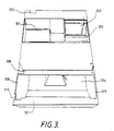
- Figure 3 is a view of the grass box from the underside. It has a lower surface with a recess 301, conforming in shape to the housing 206, and an opening 302 which mates with the opening 207 in the housing 206.
- a gasket of foam plastic material 303 round this opening seals it against the entry of outside air, and a duct within the grass box extends towards the top, so that air is drawn from above the level of the cuttings in the grass box, and grass is not drawn through in quantities sufficient to clog the turbo fan.
- a filter grid (not shown in the drawing) may be fitted loosely in the aperture 302.
- the front end of the grass box is formed with a mouth 304, fitting over the top of the aperture 201 in the mower body which houses the cutter assembly, and which in operation allows air and grass cuttings to be drawn into the grass box by the suction created by the turbo fan.
- a notch 305 allows for the passage of the motor supply lead 105 from the switch on the handle.
- Projecting flanges 306,307 assist in sealing the junction of the grass box mouth with the top of the cutter assembly aperture, and also locate the front end of the grass box with respect to the body.
- the rear portion of the grass box is located against the ends of the housing 206 by the end walls 308,309 of the recess 301.
- a cut-out 310 at the corner of the mouth accommodates a locking device for the cutting height adjustment which will be described in more detail with reference to Figure 6.
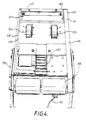
- Figure 4 shows the underside of the mower body with the cutter assembly removed. This view shows the land wheels 203,204, the rear roller 205, and the cutter assembly aperture 201. Within the aperture 201 is a pair of toothed wheels 401,402 which, as will be explained below, engage toothed segments on the cutter assembly, enabling its position to be adjusted, and so the height of cut to be varied. These toothed wheels are mounted on a shaft rotatable by an adjusting knob 403.
- skirt 404 comprising a strip running along the insides of the side members 405,406 of the body, and across its width in front of the rear rollers and behind the cutter assembly aperture. This skirt extends down almost to ground level.
- the turbo fan 407 exhausts the air which it has drawn through the grass box into the space within this skirt, and in operation the raised pressure within the skirt assists in supporting the mower above the ground, reducing the load on the land wheels and rear roller, and so making the mower easier to manoeuvre.
- FIG. 5 is a view of the cutter assembly seen from the underside.
- the assembly consists of a cutting cylinder 501 having helical blades of conventional form, and a fixed blade 502.
- a shield 503 limits the ingress of air from the side of the cutter and helps direct the grass upwards into the mouth of the grass box.
- the cylinder shaft carries a drive wheel 504 in the form of a ribbed pulley which engages a poly-V drive belt, as will be explained below.
- a pair of forked projections 505,506 extend from the points near the ends of the cutter assembly and bear, when the assembly is in position, against pins or rods within the cutter assembly aperture, allowing the assembly to have some rotational movement about these pins or rods for height adjustment.
- Figure 6 is a fragmentary view of the mower, showing the cutter assembly located in its aperture, but raised considerably above its normal operating position so as to show details of the height adjustment more clearly.
- the drive pulley 504 engages a drive belt passing over a pulley within the body, as will be explained below, and the forks 505, 506 bear against the axle of this pulley or against pins lying along its axis.
- the cutter assembly is supported between these forks and the toothed wheels 401,402, which engage toothed segments, one of which, 601, is visible in the Figure.
- the toothed wheels are rotated by means of the adjusting knob 403 to raise or lower the cutter assembly, and this adjustment causes the cutter assembly to pivot about the pins coaxial with the pulley on which the drive belt runs so that the drive pulley 504 always remains in engagement with this belt throughout the adjustment.
- a locking bolt 602 on the mower body may be engaged in any one of a series of holes 603,604 etc on the toothed segments 601 to lock it in the desired operating position.
- Figure 7 shows diagrammatically the principle of operation of the drive mechanism.
- the motor shaft carries at its outer end a pulley wheel shown in Figure 7 at 701.
- This wheel has a grooved outer surface to mate with the ribbed surface of a drive belt 702.
- the belt 702 is of the poly-V type, having a pattern of friction-increasing ridges on its inner surface, and being flat on the outer surface.
- the belt 702 passes over an idler wheel 703 mounted on an idler shaft 704.
- This wheel has a smooth outer surface.
- the belt 702 undergoes a twist of 180 o in both its forward and return portions, so that where it passes over the idler wheel 703 the flat side is in contact with the wheel and the ribbed surface faces outwards.
- the idler wheel 703 is mounted on a short axle journalled in bearings, and the forks engage a rod or a pair of pins coaxial with the shaft 704.
- the turbo fan In operation of the mower the turbo fan produces considerable suction in the grass box, and consequently at the region where cutting is taking place. This helps to hold the grass immediately in front of the cutters upright, so that it is more readily engaged by the fixed blade of the cutters, and it also removes the cut grass from the region of the cutters, so that it does not tend to clog the cutters or add unnecessarily to the load on them by falling back and being cut a second or third time.
- the grass borne in the airstream into the grass box is deposited there, where the velocity is slowed by the increased cross section offered to the airstream, entering the grass box after which the air passes through the turbo fan and is ejected within the skirt under the mower, assisting to support it, and so reducing the load on the land wheels and roller, and easing the progress of the mower so that it has less tendency to dig in, but to lift and skim over the uncut grass.
- the cutter assembly since the cutter assembly is completely removable it may be replaced by alternative equipment, for example a fertilizer distributor, a scarifier, a lawn rake, a brush for gathering fallen leaves, or removed altogether to create a vacuum refuse collector or any other device suitable for treating the surface of a lawn or path.
- Power for the alternative equipment, if any is required, may be supplied by a drive wheel engaging the belt in the same manner as described for the cutter mechanism of the mower.
Landscapes
- Life Sciences & Earth Sciences (AREA)
- Environmental Sciences (AREA)
- Harvester Elements (AREA)
Applications Claiming Priority (2)
| Application Number | Priority Date | Filing Date | Title |
|---|---|---|---|
| GB8914322 | 1989-06-22 | ||
| GB8914322A GB2233203A (en) | 1989-06-22 | 1989-06-22 | Cylinder mower |
Publications (2)
| Publication Number | Publication Date |
|---|---|
| EP0405794A2 true EP0405794A2 (de) | 1991-01-02 |
| EP0405794A3 EP0405794A3 (en) | 1993-03-24 |
Family
ID=10658859
Family Applications (1)
| Application Number | Title | Priority Date | Filing Date |
|---|---|---|---|
| EP19900306487 Withdrawn EP0405794A3 (en) | 1989-06-22 | 1990-06-14 | Cylinder mower removable cutter assembly |
Country Status (5)
| Country | Link |
|---|---|
| EP (1) | EP0405794A3 (de) |
| JP (1) | JPH03130005A (de) |
| AU (1) | AU5773690A (de) |
| CA (1) | CA2019298A1 (de) |
| GB (1) | GB2233203A (de) |
Families Citing this family (1)
| Publication number | Priority date | Publication date | Assignee | Title |
|---|---|---|---|---|
| BRPI1004032A2 (pt) * | 2010-10-08 | 2013-02-13 | Juan Miguel Mayordomo Vicente | sistema de representaÇço grÁfica aplicÁvel a superfÍcies de grama |
Family Cites Families (12)
| Publication number | Priority date | Publication date | Assignee | Title |
|---|---|---|---|---|
| GB595659A (en) * | 1945-07-06 | 1947-12-11 | Byfords Ltd | Improvements in lawn mowers |
| GB320957A (en) * | 1928-07-28 | 1929-10-28 | Webb H C & Co Ltd | Improvements relating to lawn mowers |
| GB417006A (en) * | 1933-07-06 | 1934-09-26 | Dronsfield Brothers Ltd | Improvements in lawn mowers |
| GB513493A (en) * | 1938-04-08 | 1939-10-13 | Charles Francis Booton | Improvements in and relating to lawnmowers and the like |
| GB1157626A (en) * | 1965-07-28 | 1969-07-09 | Wilkinson Sword Ltd | Improvements in or relating to Machines for Cutting Grass and like Vegetable Matter |
| GB1180381A (en) * | 1965-11-03 | 1970-02-04 | Qualcast Ltd | Improvements in or relating to Lawn Mowers |
| GB1241752A (en) * | 1968-09-18 | 1971-08-04 | Ransomes Sims & Jefferies Ltd | Improvements in or relating to mowing machines |
| US3783592A (en) * | 1970-05-06 | 1974-01-08 | K Schraut | Garden grooming machine and rotor therefor |
| DE2607389A1 (de) * | 1976-02-24 | 1977-08-25 | Adolf Maier | Walzen-rasenmaeher |
| GB1540217A (en) * | 1976-06-15 | 1979-02-07 | Sisis Equip | Turf treatment apparatus |
| GB1541426A (en) * | 1976-11-22 | 1979-02-28 | Sisis Equip | Turf-treatment means |
| GB2116413B (en) * | 1982-02-26 | 1985-05-22 | Birmid Qualcast | Lawnmower |
-
1989
- 1989-06-22 GB GB8914322A patent/GB2233203A/en not_active Withdrawn
-
1990
- 1990-06-14 EP EP19900306487 patent/EP0405794A3/en not_active Withdrawn
- 1990-06-19 CA CA 2019298 patent/CA2019298A1/en not_active Abandoned
- 1990-06-21 AU AU57736/90A patent/AU5773690A/en not_active Abandoned
- 1990-06-22 JP JP16296490A patent/JPH03130005A/ja active Pending
Also Published As
| Publication number | Publication date |
|---|---|
| GB8914322D0 (en) | 1989-08-09 |
| GB2233203A (en) | 1991-01-09 |
| JPH03130005A (ja) | 1991-06-03 |
| EP0405794A3 (en) | 1993-03-24 |
| AU5773690A (en) | 1991-01-03 |
| CA2019298A1 (en) | 1990-12-22 |
Similar Documents
| Publication | Publication Date | Title |
|---|---|---|
| EP0457433B1 (de) | Rasenmäher | |
| US2539779A (en) | Rotating cutting disk type power mower | |
| US4823464A (en) | Grass trimmer | |
| US5117616A (en) | Mulching lawn mower | |
| EP0404436B1 (de) | Spindelmäher mit Saugkraft-Grasschnitt | |
| US2491544A (en) | Lawn mower | |
| EP0300383A2 (de) | Rasenmäher, dessen Benutzer hinterher läuft | |
| US20200022306A1 (en) | Mower apparatus | |
| EP0616760A1 (de) | Vorrichtung zum Behandeln von Rasen | |
| US5060461A (en) | Semi-hover cylinder mower | |
| US2782582A (en) | Power mower with endless belt cutting means | |
| EP0405794A2 (de) | Käfigmäher mit abnehmbarer Schneidvorrichtung | |
| CA1268951A (en) | Lawnmower | |
| CA1138654A (en) | Power rake foot guard | |
| US3952483A (en) | Trimmer with laterally positioned blade and separately adjustable front and rear wheels | |
| GB2343607A (en) | A lawn mower with two blades set at different heights | |
| GB2079575A (en) | Lawn-mower | |
| US3899866A (en) | Lawn mower | |
| EP0523866B1 (de) | Rasenmäher | |
| EP0552000A1 (de) | Rotationsmähvorrichtung | |
| JPH0142991Y2 (de) | ||
| EP0650663A1 (de) | Sammelnder Trimmer | |
| JPH0437683B2 (de) | ||
| JPH0316425Y2 (de) | ||
| GB1587471A (en) | Cylinder mowers |
Legal Events
| Date | Code | Title | Description |
|---|---|---|---|
| PUAI | Public reference made under article 153(3) epc to a published international application that has entered the european phase |
Free format text: ORIGINAL CODE: 0009012 |
|
| AK | Designated contracting states |
Kind code of ref document: A2 Designated state(s): BE DE DK ES FR GB IT NL SE |
|
| 17P | Request for examination filed |
Effective date: 19901221 |
|
| PUAL | Search report despatched |
Free format text: ORIGINAL CODE: 0009013 |
|
| AK | Designated contracting states |
Kind code of ref document: A3 Designated state(s): BE DE DK ES FR GB IT NL SE |
|
| 17Q | First examination report despatched |
Effective date: 19940420 |
|
| STAA | Information on the status of an ep patent application or granted ep patent |
Free format text: STATUS: THE APPLICATION HAS BEEN WITHDRAWN |
|
| 18W | Application withdrawn |
Withdrawal date: 19940822 |