EP0405813A2 - Dispositif d'attelage d'un outil de travail - Google Patents
Dispositif d'attelage d'un outil de travail Download PDFInfo
- Publication number
- EP0405813A2 EP0405813A2 EP90306610A EP90306610A EP0405813A2 EP 0405813 A2 EP0405813 A2 EP 0405813A2 EP 90306610 A EP90306610 A EP 90306610A EP 90306610 A EP90306610 A EP 90306610A EP 0405813 A2 EP0405813 A2 EP 0405813A2
- Authority
- EP
- European Patent Office
- Prior art keywords
- coupler
- receiving means
- latch
- implement
- coupling
- Prior art date
- Legal status (The legal status is an assumption and is not a legal conclusion. Google has not performed a legal analysis and makes no representation as to the accuracy of the status listed.)
- Granted
Links
Images






Classifications
-
- E—FIXED CONSTRUCTIONS
- E02—HYDRAULIC ENGINEERING; FOUNDATIONS; SOIL SHIFTING
- E02F—DREDGING; SOIL-SHIFTING
- E02F3/00—Dredgers; Soil-shifting machines
- E02F3/04—Dredgers; Soil-shifting machines mechanically-driven
- E02F3/28—Dredgers; Soil-shifting machines mechanically-driven with digging tools mounted on a dipper- or bucket-arm, i.e. there is either one arm or a pair of arms, e.g. dippers, buckets
- E02F3/36—Component parts
- E02F3/3604—Devices to connect tools to arms, booms or the like
- E02F3/3609—Devices to connect tools to arms, booms or the like of the quick acting type, e.g. controlled from the operator seat
- E02F3/3622—Devices to connect tools to arms, booms or the like of the quick acting type, e.g. controlled from the operator seat with a hook and a locking element acting on a pin
-
- E—FIXED CONSTRUCTIONS
- E02—HYDRAULIC ENGINEERING; FOUNDATIONS; SOIL SHIFTING
- E02F—DREDGING; SOIL-SHIFTING
- E02F3/00—Dredgers; Soil-shifting machines
- E02F3/04—Dredgers; Soil-shifting machines mechanically-driven
- E02F3/28—Dredgers; Soil-shifting machines mechanically-driven with digging tools mounted on a dipper- or bucket-arm, i.e. there is either one arm or a pair of arms, e.g. dippers, buckets
- E02F3/36—Component parts
- E02F3/3604—Devices to connect tools to arms, booms or the like
- E02F3/3609—Devices to connect tools to arms, booms or the like of the quick acting type, e.g. controlled from the operator seat
- E02F3/3659—Devices to connect tools to arms, booms or the like of the quick acting type, e.g. controlled from the operator seat electrically-operated
-
- F—MECHANICAL ENGINEERING; LIGHTING; HEATING; WEAPONS; BLASTING
- F16—ENGINEERING ELEMENTS AND UNITS; GENERAL MEASURES FOR PRODUCING AND MAINTAINING EFFECTIVE FUNCTIONING OF MACHINES OR INSTALLATIONS; THERMAL INSULATION IN GENERAL
- F16B—DEVICES FOR FASTENING OR SECURING CONSTRUCTIONAL ELEMENTS OR MACHINE PARTS TOGETHER, e.g. NAILS, BOLTS, CIRCLIPS, CLAMPS, CLIPS OR WEDGES; JOINTS OR JOINTING
- F16B2200/00—Constructional details of connections not covered for in other groups of this subclass
- F16B2200/69—Redundant disconnection blocking means
-
- Y—GENERAL TAGGING OF NEW TECHNOLOGICAL DEVELOPMENTS; GENERAL TAGGING OF CROSS-SECTIONAL TECHNOLOGIES SPANNING OVER SEVERAL SECTIONS OF THE IPC; TECHNICAL SUBJECTS COVERED BY FORMER USPC CROSS-REFERENCE ART COLLECTIONS [XRACs] AND DIGESTS
- Y10—TECHNICAL SUBJECTS COVERED BY FORMER USPC
- Y10T—TECHNICAL SUBJECTS COVERED BY FORMER US CLASSIFICATION
- Y10T403/00—Joints and connections
- Y10T403/60—Biased catch or latch
- Y10T403/608—Pivoted
Definitions
- This invention relates to couplers for attaching implements, such as loading or digging buckets or fork tines, to the end of a support member or members of, for example, a handling, loading or digging machine.
- a quick-attach coupler for coupling an implement to a machine
- the coupler including attachment means for attaching the coupler to the machine, upper receiving means for receiving an upper coupling means on the implement, lower receiving means for receiving a lower coupling means on the implement, said lower receiving means having an opening including a locating formation which retains the lower coupling means in the lower receiving means, and latch means associated with the upper receiving means for retaining the upper coupling means within the upper receiving means and hence preventing the lower coupling means disengaging the locating formation of the lower receiving means.
- a quick-attach coupler in accordance with the present invention when applied, for example, to a twin arm front end loader is that the coupler can be designed to pick up both the narrower type of implement which is normally slung between the loader arms via coupling means projecting from the sides of the implement and also wider implements designed to be mounted on the loader arms via coupling means on the back of the implement.
- the attachment means comprises first attachment means for pivotally attaching the coupler to a support member or members of the machine and a second attachment means for connecting the coupler to an implement pivotting mechanism of the machine.
- the upper receiving means comprises a pair of upwardly opening slots and the lower receiving means comprises a pair of horizontal opening slots, both pairs of slots being spaced transversely of the coupler.
- the horizontally opening slots which constitute the lower receiving means are each provided with a tapering lead-in to assist in guiding the lower coupling means on the implement into the slot.
- the locating formation of the lower receiving means may comprise a threshold over which the lower coupling means passes on its way into the receiving means.
- the latch means may comprise a pivotally mounted latch which can be held in a first position allowing free access to the upper receiving means during coupling or de-coupling of an implement and in a second position in which the upper coupling means is held captive in the upper receiving means to prevent disengagement of the lower coupling means from the locating means of the lower receiving means.
- the latch may be held in its two positions by a pin manually inserted through aligned holes in the latch and the remainder of the coupler.
- a spring-loaded detent acting between the latch and the remainder of the coupler may be used.
- the latch can be pivotted between its two positions by an actuating means (such as an hydraulic or pneumatic cylinder or solenoid) which can be operated by the machine operator from his driving seat.
- FIG. 1 shows a front end loader 10 mounted on a tractor 11.
- the front end loader has a spaced pair of support arms which are pivotally mounted at 13 for raising and lowering in a conventional manner by a pair of lift rams 14, one lift ram acting on each loader arm.
- the sides 16 of the bucket are provided with lower coupling means in the form of projecting pins 17, and upper coupling means in the form of projecting pins 18.
- the pins 17 and 18 are received by lower and upper receiving means 19 and 20, provided in a quick coupler 21 in accordance with the present invention.
- the quick coupler 21 is itself mounted on each loader arm 12 via a lower pivotal connection 22.
- Each loader arm also carries a bucket tipping and crowding linkage 23, which includes an hydraulic cylinder 24.
- Each tipping and crowding linkage being connected to the quick coupler 21 via an upper pivotal connection 25.
- the quick coupler 21 comprises a pair of heavy duty side plates 26 which are inter-connected by a tubular member 27, which is welded between arms 28.
- the lower pivotal connection 22 with each loader arm is provided by a pin 29 which is welded between a pair of support plates 30 which are in turn welded onto either side of each heavy duty plate 26.
- Each pin 29 is held in a retaining recess 29a in the end of its respective loader arm by a spring-loaded latch 29b (see Figure 1).
- the upper pivotal connection of the coupler 21 with each tipping and crowding linkage 23 is provided by a pair of plates 31 (see Figure 8) which are welded onto each side of each heavy duty plate 26 and are provided with reinforcing pivot bosses 32 which receive a pivot pin 25.
- Each heavy duty plate 26 includes a lower receiving means in the form of a horizontally opening slot 19 with a tapering lead-in 33.
- Each slot 19 has a locating formation in the form of a threshold 19a which retains the associated pin 17 in the slot when the bucket 15 is fully mounted on the quick-attach coupler.
- each heavy duty plate 26 At the upper end of each heavy duty plate 26 an upper receiving means in the form an upwardly opening slot 20 is provided which receives the associated upper pin 18 on the bucket.
- Each slot 20 has a pivoting latch 34 associated therewith.
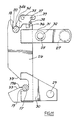
- Each latch is mounted on a pivot pin 35 and has its centre of gravity located such as to bias the latch against an associated stop 36. With the latch in the position shown in Figure 6, the upper pins 18 are held captive in the upwardly opening slot 20, thus preventing disengagement of the lower pins 17 from their associated slots 19.
- Each latch is provided with 2 holes 37 and 38, each of which can co-operate with the corresponding hole 39 in the associated side plate 26, so that the latch 34 can be held in the position shown in Figure 6 by inserting a pin through the aligned holes 37 and 39 or can be held in a position in which the end 34a of the latch is clear of the slot 20, by inserting a pin through aligned holes 38 and 39.
- Figures 9 and 10 show the sequence of events involved in picking up a bucket using the quick-attach coupler.
- the operator positions the coupler at the appropriate height to engage the upper pins 18 with the slot 20, using lift rams 14 and the tipping/crowding cylinders 24.
- the lift arms 12 are raised to lift the bucket on the upper pins 18 and the coupler 21 is pivotting in the direction of Arrow X of Figure 8 using the cylinders 24 to engage the lower pin 17 on the tapering lead-in 33 of the lower receiving slots 19.
- the upper pins 18 also rise in the upper slots 20 until eventually the pins 17 ride over the thresholds 19a and drop into the bottom of slots 19.
- Figure 11 shows a modified form of quick-coupler in which arms 28 are eliminated and plates 31 are extended to carry the tubular member 27. This produces a more rigid structure with improved freedom of pivotting for the bucket.
- FIG. 12 An alternative latch arrangement is shown in Figure 12 in which the latch 34 is partially recessed into the plate 26 and is held in its two positions by a spring-loaded ball detent 50 which engages one of two recesses 51 which replace the holes 37 and 38.
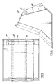
- Figures 13 and 14 show a quick-attach coupler 59 in accordance with the present invention for coupling a backhoe digging bucket to the end of a backhoe dipperstick.
- Side plates 60 each include upper and lower slots 65 and 66 of a similar from to slots 20 and 19 described above in relation to coupler 21 and each upper slot is provided with a pivotting latch 67 mounted on a shaft 68 which extends between the plates60.
- the latches 67 are mounted on the inside of plates 60 and are movable, between the position shown in Figure 14 when they project into slots 65 to a position when they are clear of the slots, by a fluid pressure operated cylinder 69 via an arm 70 on shaft 68.
- This cylinder is supplied with hydraulic fluid via an hydraulic system not shown which is controlled by a lever or other control provided adjacent the drivers seat so that the latches can be moved between the above two positions without the machine operator leaving the driving seat.
- the upper and lower slots 65 and 66 receive upper and lower coupling pins 71 and 72 which extend between two flanges provided on the rear of the digging bucket.
- the bucket is coupled to the coupler 59 in the same manner described above in relation to coupler 21.
- a pneumatically operated cylinder could be used in place of the cylinder 69.
- the latches 67 could be moved between their two positions by an electrically operated actuator such as a solenoid or linear actuator or other remotely controlled device.
- the principal of the remote operation of latches 67 could be used on the latches 34 of the loader coupler 21 described above.
- the various actuators described above may be double-acting or single acting with the latch biased towards one of the latch positions and the actuator arranged to move the latch to the other latch position against the action of the bias.
- Figure 15 shows a still further form of quick-attach coupler in accordance with the present invention for coupling a backhoe digging bucket to the end of a dipperstick in which components of a similar function to those of the coupler of Figure 13 have been similarly numbered.
- a spring 76 biases the latch to its engaged position (shown in full lines) against a stop 77 and a linear electrical actuator or solenoid 75 is used to move the latch from its engaged position to its dotted releasing position 67a.
Landscapes
- Engineering & Computer Science (AREA)
- Mechanical Engineering (AREA)
- Mining & Mineral Resources (AREA)
- Civil Engineering (AREA)
- General Engineering & Computer Science (AREA)
- Structural Engineering (AREA)
- Shovels (AREA)
Applications Claiming Priority (2)
| Application Number | Priority Date | Filing Date | Title |
|---|---|---|---|
| GB8914927 | 1989-06-29 | ||
| GB898914927A GB8914927D0 (en) | 1989-06-29 | 1989-06-29 | Implement attachment coupler |
Publications (3)
| Publication Number | Publication Date |
|---|---|
| EP0405813A2 true EP0405813A2 (fr) | 1991-01-02 |
| EP0405813A3 EP0405813A3 (en) | 1991-08-14 |
| EP0405813B1 EP0405813B1 (fr) | 1996-09-11 |
Family
ID=10659255
Family Applications (1)
| Application Number | Title | Priority Date | Filing Date |
|---|---|---|---|
| EP90306610A Expired - Lifetime EP0405813B1 (fr) | 1989-06-29 | 1990-06-18 | Dispositif d'attelage d'un outil de travail |
Country Status (5)
| Country | Link |
|---|---|
| US (1) | US5141385A (fr) |
| EP (1) | EP0405813B1 (fr) |
| DE (1) | DE69028453T2 (fr) |
| GB (1) | GB8914927D0 (fr) |
| ZA (1) | ZA904876B (fr) |
Cited By (17)
| Publication number | Priority date | Publication date | Assignee | Title |
|---|---|---|---|---|
| WO1996002706A1 (fr) * | 1994-07-13 | 1996-02-01 | Clark Equipment Company | Actionneur mecanique pour plaque de fixation |
| WO1999042670A1 (fr) * | 1998-02-06 | 1999-08-26 | Metaalwarenfabriek A.P. Verachtert B.V. | Excavatrice et outil couple a une fleche d'excavatrice combines |
| GB2330570B (en) * | 1998-09-08 | 1999-09-15 | Miller Ronald Keith | Quick coupler for bucket excavators |
| WO2001059222A1 (fr) * | 2000-02-11 | 2001-08-16 | Miller Welding Engineers Ltd. | Coupleur universel pour bennes d'excavation |
| US6625909B1 (en) | 1998-09-08 | 2003-09-30 | Doreen Jacqueline Miller | Coupler for bucket excavators |
| GB2433246A (en) * | 2005-12-13 | 2007-06-20 | Tower Street Technologies Ltd | Coupler with improved jaw configuration |
| FR2900168A1 (fr) * | 2006-04-21 | 2007-10-26 | Morin Soc Par Actions Simplifi | Coupleur pour engin de travaux a deverrouillage mixte |
| GB2441322A (en) * | 2006-09-04 | 2008-03-05 | Miller Uk Ltd | Coupler with gravity operated latch |
| WO2008029112A3 (fr) * | 2006-09-04 | 2008-05-29 | Miller Uk Ltd | Coupleur |
| US7493712B2 (en) | 2003-09-18 | 2009-02-24 | Mccormick Patrick | Excavator tool quick attachment device |
| USD638037S1 (en) | 2010-10-22 | 2011-05-17 | Miller International Ltd. | Coupler |
| USD638039S1 (en) | 2010-10-22 | 2011-05-17 | Miller International Ltd. | Coupler with tapered transitions |
| USD638038S1 (en) | 2010-10-22 | 2011-05-17 | Miller International Ltd. | Lifting eye on a coupler |
| USD638448S1 (en) | 2010-10-22 | 2011-05-24 | Miller International Ltd. | Machined pads on a coupler |
| EP1852555B1 (fr) * | 2006-05-02 | 2012-09-12 | Kinshofer GmbH | Verrou de sécurité pour une attache rapide |
| USD673982S1 (en) | 2010-10-22 | 2013-01-08 | Miller International Ltd. | Operator-visible warning symbol on a coupler |
| DE202011110652U1 (de) | 2011-10-05 | 2015-06-03 | Caterpillar Work Tools B. V. | Abbruchgerät |
Families Citing this family (43)
| Publication number | Priority date | Publication date | Assignee | Title |
|---|---|---|---|---|
| USD351604S (en) | 1993-05-07 | 1994-10-18 | Arthur Groover | Self latching hitch |
| US5529419A (en) * | 1994-07-25 | 1996-06-25 | Jrb Company, Inc. | High visibility coupler for front end loader |
| US5490340A (en) * | 1994-08-31 | 1996-02-13 | Muncy; Robert G. | Root grubber |
| US5692852A (en) * | 1996-04-24 | 1997-12-02 | Entek Manufacturing Company | Quick connect system for excavator buckets |
| US5779429A (en) * | 1996-09-10 | 1998-07-14 | Kendall Manufacturing, Inc. | Mechanism allowing quick implement attachment to tractors |
| US5779303A (en) * | 1997-02-03 | 1998-07-14 | Chrome Specialties, Inc. | Support bracket system for securing motorcycle backrests |
| US5836734A (en) * | 1997-10-17 | 1998-11-17 | Deere & Company | Latching device with detent |
| US6138770A (en) * | 1998-01-26 | 2000-10-31 | Kayser; Howard H. | Lawn tractor load-carrying hitch/frame and spraying apparatus |
| US6074120A (en) * | 1998-03-27 | 2000-06-13 | Caterpillar Commercial Sarl | Quick coupler assembly |
| JPH11315551A (ja) | 1998-03-27 | 1999-11-16 | Nippon Pneumatic Mfg Co Ltd | 建設機械における迅速接続装置 |
| US6350079B1 (en) * | 1998-07-28 | 2002-02-26 | Caterpillar S.A.R.L. | Quick coupler assembly |
| US6332748B1 (en) | 1999-11-09 | 2001-12-25 | Deere & Company | Rotating pawl tool latch |
| US6386821B1 (en) | 1999-12-16 | 2002-05-14 | Bush Hog, L.L.C. | Mounting system for mid-mount front end loaders |
| US20030012597A1 (en) * | 2001-07-16 | 2003-01-16 | Miller Darin R. | Work tool locking device |
| US7306395B2 (en) * | 2001-11-29 | 2007-12-11 | Jrb Attachments, Llc | Spread-style coupler with supplemental lock system |
| US6902346B2 (en) | 2002-03-15 | 2005-06-07 | Hendrix Manufacturing, Ltd. | Hydraulic coupler |
| WO2004038110A1 (fr) * | 2002-10-24 | 2004-05-06 | Bruce Archibald Short | Connecteur pour outils de terrassement |
| GB2415354A (en) * | 2004-06-22 | 2005-12-28 | Agco Sa | Tractor front hitch |
| US7351028B2 (en) * | 2005-01-18 | 2008-04-01 | Lucky Friday Corp. | Work machine adapter and method |
| JP4247211B2 (ja) * | 2005-07-05 | 2009-04-02 | ヤンマー株式会社 | トラクタ・ローダ・バックホーにおける掘削装置のロック機構 |
| US7673403B2 (en) * | 2006-06-08 | 2010-03-09 | Thomas Edward Bridges | Method and apparatus for unassisted implement connection |
| US20080172913A1 (en) * | 2007-01-22 | 2008-07-24 | Bailey Alan D | Quick-attach mechanism for attaching a blade to an off-road vehicle |
| US7984575B2 (en) * | 2007-07-05 | 2011-07-26 | Caterpillar Inc. | Quick coupler assembly |
| US20090282712A1 (en) * | 2008-05-15 | 2009-11-19 | Pruszynski Edwin | Coupler for excavating machines and the like |
| DE102009046213B4 (de) * | 2009-10-30 | 2014-02-13 | Wilhelm Stoll Maschinenfabrik Gmbh | Wechselrahmen für einen Frontlader |
| US8739436B2 (en) | 2010-11-12 | 2014-06-03 | Curt J. Hill | Quick-attach assembly for attaching an implement to an off-road vehicle |
| US8381422B2 (en) | 2010-11-12 | 2013-02-26 | Curt J. Hill | Method and means for converting a blade attachment of an off-road vehicle to a quick-attach blade |
| US8322581B2 (en) | 2011-04-21 | 2012-12-04 | Hill Curt J | Push tube adapter for an off-road vehicle |
| US8974137B2 (en) | 2011-12-22 | 2015-03-10 | Caterpillar Inc. | Quick coupler |
| US9217235B2 (en) | 2012-05-30 | 2015-12-22 | Caterpillar Inc. | Tool coupler system having multiple pressure sources |
| US8869437B2 (en) | 2012-05-30 | 2014-10-28 | Caterpillar Inc. | Quick coupler |
| US8684623B2 (en) | 2012-05-30 | 2014-04-01 | Caterpillar Inc. | Tool coupler having anti-release mechanism |
| US9228314B2 (en) | 2013-05-08 | 2016-01-05 | Caterpillar Inc. | Quick coupler hydraulic control system |
| US9903095B2 (en) * | 2015-01-30 | 2018-02-27 | Caterpillar Inc. | Tool coupler |
| TWI708900B (zh) | 2016-01-20 | 2020-11-01 | 奧地利商奧羅科技有限公司 | 旋轉式滑動軸承、具有旋轉式滑動軸承之裝置、具有旋轉式滑動軸承之裝置的用途及高爾夫球車 |
| US10463153B2 (en) | 2016-06-09 | 2019-11-05 | Steelcase Inc. | Seating arrangement |
| US10294629B1 (en) * | 2018-05-16 | 2019-05-21 | Deere & Company | Holder for coupling a work implement to a work vehicle |
| US11214936B2 (en) | 2018-07-10 | 2022-01-04 | Venture Products, Inc. | Power unit with salt spreader and salt spreader for use therewith |
| US10550541B1 (en) | 2019-04-25 | 2020-02-04 | Deere & Company | Connection system for connecting an implement to a work vehicle |
| US11536009B2 (en) | 2019-07-26 | 2022-12-27 | Deere & Company | System for detecting locking pin engagement of an implement |
| USD931909S1 (en) | 2020-02-04 | 2021-09-28 | Deere & Company | Implement connection system |
| FR3161438A1 (fr) * | 2024-04-19 | 2025-10-24 | Klac Industrie Sas | attache rapide à grande sécurité |
| FR3161439A1 (fr) * | 2024-04-19 | 2025-10-24 | Klac Industrie Sas | Attache rapide pour engins de travaux publics |
Family Cites Families (19)
| Publication number | Priority date | Publication date | Assignee | Title |
|---|---|---|---|---|
| US3606052A (en) * | 1969-07-03 | 1971-09-20 | Al Mfg Co Du | Loader attachment quick coupler device |
| GB1582398A (en) * | 1976-07-05 | 1981-01-07 | Komatsu Mfg Co Ltd | Vehicle for releasably carrying an implement |
| US4148106A (en) * | 1977-12-27 | 1979-04-10 | Gallien John W | Furniture fastener system |
| US4214840A (en) * | 1979-01-18 | 1980-07-29 | J. H. Beales Steel Fabricators, Ltd. | Quick-release coupler |
| US4355945A (en) * | 1979-12-03 | 1982-10-26 | Ware Machine Service, Inc. | Tool mounting apparatus |
| AU544156B2 (en) * | 1980-11-17 | 1985-05-16 | Eimco (Great Britain) Ltd. | A coupling system for earth-moving equipment |
| NZ199611A (en) * | 1981-02-05 | 1984-09-28 | Maroochy Shire Council | Quick release and attachment assembly for construction equipment tools |
| US4413366A (en) * | 1981-05-26 | 1983-11-08 | Leggett & Platt, Incorporated | Bed frame |
| US4436477A (en) * | 1982-03-25 | 1984-03-13 | Farmhand, Inc. | Quick attachment carrier assembly |
| DE3312442C2 (de) * | 1983-04-07 | 1986-05-28 | Karl Schaeff GmbH & Co, Maschinenfabrik, 7183 Langenburg | Schnellwechselvorrichtung für Arbeitswerkzeuge an einem Baggerausleger |
| US4661036A (en) * | 1984-06-28 | 1987-04-28 | J. I. Case Company | Backhoe hydraulic latch arrangement |
| DE3437931A1 (de) * | 1984-10-17 | 1986-04-24 | Macmoter S.P.A., Modigliana | Anbauhalter |
| GB8500911D0 (en) * | 1985-01-15 | 1985-02-20 | Mason S T | Quick-change fitting |
| GB2177674B (en) * | 1985-07-10 | 1988-10-05 | Bamford Excavators Ltd | Mounting a working implement |
| GB8613876D0 (en) * | 1986-06-07 | 1986-07-09 | J I Case Europ Ltd | Material-handling vehicle |
| NZ222864A (en) * | 1987-06-04 | 1991-02-26 | William John Balemi | Connector for attaching implements to vehicle boom |
| AT392307B (de) * | 1987-09-25 | 1991-03-11 | Winkelbauer Franz | Kupplungseinrichtung |
| US4871292A (en) * | 1987-12-17 | 1989-10-03 | Richard Milanowski | System for attaching and locking material handling tools to a dipper boom |
| CH675266A5 (fr) * | 1987-12-22 | 1990-09-14 | Zepf Hans Rudolf |
-
1989
- 1989-06-29 GB GB898914927A patent/GB8914927D0/en active Pending
-
1990
- 1990-06-18 DE DE69028453T patent/DE69028453T2/de not_active Expired - Fee Related
- 1990-06-18 EP EP90306610A patent/EP0405813B1/fr not_active Expired - Lifetime
- 1990-06-22 ZA ZA904876A patent/ZA904876B/xx unknown
- 1990-06-25 US US07/542,546 patent/US5141385A/en not_active Expired - Fee Related
Cited By (25)
| Publication number | Priority date | Publication date | Assignee | Title |
|---|---|---|---|---|
| WO1996002706A1 (fr) * | 1994-07-13 | 1996-02-01 | Clark Equipment Company | Actionneur mecanique pour plaque de fixation |
| WO1999042670A1 (fr) * | 1998-02-06 | 1999-08-26 | Metaalwarenfabriek A.P. Verachtert B.V. | Excavatrice et outil couple a une fleche d'excavatrice combines |
| GB2330570B (en) * | 1998-09-08 | 1999-09-15 | Miller Ronald Keith | Quick coupler for bucket excavators |
| WO2000014342A1 (fr) * | 1998-09-08 | 2000-03-16 | Doreen Jacqueline Miller | Dispositif d'attache rapide destine a des excavateurs a godets |
| US6625909B1 (en) | 1998-09-08 | 2003-09-30 | Doreen Jacqueline Miller | Coupler for bucket excavators |
| WO2001059222A1 (fr) * | 2000-02-11 | 2001-08-16 | Miller Welding Engineers Ltd. | Coupleur universel pour bennes d'excavation |
| US6922926B2 (en) | 2000-02-11 | 2005-08-02 | Miller Uk Limited | Universal coupler for excavator buckets |
| US7493712B2 (en) | 2003-09-18 | 2009-02-24 | Mccormick Patrick | Excavator tool quick attachment device |
| GB2433246B (en) * | 2005-12-13 | 2010-01-20 | Tower Street Technologies Ltd | Coupler with improved jaw configuration |
| GB2433246A (en) * | 2005-12-13 | 2007-06-20 | Tower Street Technologies Ltd | Coupler with improved jaw configuration |
| WO2007122317A1 (fr) * | 2006-04-21 | 2007-11-01 | Morin S.A.S. | Coupleur pour engin de travaux a deverrouillage mixte |
| FR2900168A1 (fr) * | 2006-04-21 | 2007-10-26 | Morin Soc Par Actions Simplifi | Coupleur pour engin de travaux a deverrouillage mixte |
| EP1852555B1 (fr) * | 2006-05-02 | 2012-09-12 | Kinshofer GmbH | Verrou de sécurité pour une attache rapide |
| US8256148B2 (en) | 2006-09-04 | 2012-09-04 | Miller Uk Limited | Coupler |
| GB2441322B (en) * | 2006-09-04 | 2011-03-09 | Miller Uk Ltd | Coupler |
| US7984576B2 (en) | 2006-09-04 | 2011-07-26 | Miller Uk Limited | Coupler |
| WO2008029112A3 (fr) * | 2006-09-04 | 2008-05-29 | Miller Uk Ltd | Coupleur |
| GB2441322A (en) * | 2006-09-04 | 2008-03-05 | Miller Uk Ltd | Coupler with gravity operated latch |
| US8448357B2 (en) | 2006-09-04 | 2013-05-28 | Miller Uk Limited | Coupler |
| USD638037S1 (en) | 2010-10-22 | 2011-05-17 | Miller International Ltd. | Coupler |
| USD638039S1 (en) | 2010-10-22 | 2011-05-17 | Miller International Ltd. | Coupler with tapered transitions |
| USD638038S1 (en) | 2010-10-22 | 2011-05-17 | Miller International Ltd. | Lifting eye on a coupler |
| USD638448S1 (en) | 2010-10-22 | 2011-05-24 | Miller International Ltd. | Machined pads on a coupler |
| USD673982S1 (en) | 2010-10-22 | 2013-01-08 | Miller International Ltd. | Operator-visible warning symbol on a coupler |
| DE202011110652U1 (de) | 2011-10-05 | 2015-06-03 | Caterpillar Work Tools B. V. | Abbruchgerät |
Also Published As
| Publication number | Publication date |
|---|---|
| DE69028453T2 (de) | 1997-02-06 |
| ZA904876B (en) | 1992-02-26 |
| DE69028453D1 (de) | 1996-10-17 |
| EP0405813B1 (fr) | 1996-09-11 |
| US5141385A (en) | 1992-08-25 |
| GB8914927D0 (en) | 1989-08-23 |
| EP0405813A3 (en) | 1991-08-14 |
Similar Documents
| Publication | Publication Date | Title |
|---|---|---|
| US5141385A (en) | Implement attachment coupler | |
| US5692850A (en) | High visibility coupler for front end loader | |
| US3794195A (en) | Quick-attaching mechanism | |
| US4125952A (en) | Bucket attachment | |
| EP0447119B1 (fr) | Engin de terrassement | |
| CA1307767C (fr) | Adaptateur d'outil pour chargeuse frontale | |
| CA1298814C (fr) | Accessoire de manutention du materiel, destine a etre monte sur un tracteur muni d'un attelage multi-points | |
| US5732488A (en) | Quick hitch assembly | |
| US4812103A (en) | Implement-coupling assembly for material-handling apparatus | |
| EP0091943B1 (fr) | Auge detachable pour dispositifs de terrassement | |
| US4669947A (en) | Earth moving implement | |
| US4068959A (en) | Coupler apparatus | |
| US4929143A (en) | Quick-attaching mechanism | |
| US5599158A (en) | Linkage arrangement for a wheel loader | |
| US4850790A (en) | Hydraulically actuated coupler for industrial, agricultural, or earth-moving vehicle | |
| US8500386B2 (en) | Latching system for automatically securing front-mounted loader mast to tractor mounting frame | |
| US6139212A (en) | Coupler for excavating machines and the like having fixed and moveable jaws | |
| US6776571B2 (en) | Fork attachment for backhoe | |
| US6709224B2 (en) | Implement coupling assembly | |
| US6119377A (en) | Backhoe attachment for skid loaders | |
| EP0578447A1 (fr) | Attelage pour outil | |
| CA2136663A1 (fr) | Benne preneuse modifiee et circuit de commande hydraulique | |
| US4239085A (en) | Side shift assembly for earth-working implements | |
| EP0818584A2 (fr) | Agencement de liaison pour machine de chargement | |
| US11952738B2 (en) | Attachment coupler |
Legal Events
| Date | Code | Title | Description |
|---|---|---|---|
| PUAI | Public reference made under article 153(3) epc to a published international application that has entered the european phase |
Free format text: ORIGINAL CODE: 0009012 |
|
| AK | Designated contracting states |
Kind code of ref document: A2 Designated state(s): DE FR GB IT |
|
| PUAL | Search report despatched |
Free format text: ORIGINAL CODE: 0009013 |
|
| AK | Designated contracting states |
Kind code of ref document: A3 Designated state(s): DE FR GB IT |
|
| 17P | Request for examination filed |
Effective date: 19920213 |
|
| 17Q | First examination report despatched |
Effective date: 19930818 |
|
| GRAH | Despatch of communication of intention to grant a patent |
Free format text: ORIGINAL CODE: EPIDOS IGRA |
|
| GRAH | Despatch of communication of intention to grant a patent |
Free format text: ORIGINAL CODE: EPIDOS IGRA |
|
| GRAA | (expected) grant |
Free format text: ORIGINAL CODE: 0009210 |
|
| AK | Designated contracting states |
Kind code of ref document: B1 Designated state(s): DE FR GB IT |
|
| ET | Fr: translation filed | ||
| ITF | It: translation for a ep patent filed | ||
| REF | Corresponds to: |
Ref document number: 69028453 Country of ref document: DE Date of ref document: 19961017 |
|
| PGFP | Annual fee paid to national office [announced via postgrant information from national office to epo] |
Ref country code: GB Payment date: 19970506 Year of fee payment: 8 |
|
| PGFP | Annual fee paid to national office [announced via postgrant information from national office to epo] |
Ref country code: FR Payment date: 19970530 Year of fee payment: 8 |
|
| PLBE | No opposition filed within time limit |
Free format text: ORIGINAL CODE: 0009261 |
|
| STAA | Information on the status of an ep patent application or granted ep patent |
Free format text: STATUS: NO OPPOSITION FILED WITHIN TIME LIMIT |
|
| PGFP | Annual fee paid to national office [announced via postgrant information from national office to epo] |
Ref country code: DE Payment date: 19970722 Year of fee payment: 8 |
|
| 26N | No opposition filed | ||
| PG25 | Lapsed in a contracting state [announced via postgrant information from national office to epo] |
Ref country code: GB Free format text: LAPSE BECAUSE OF NON-PAYMENT OF DUE FEES Effective date: 19980618 |
|
| GBPC | Gb: european patent ceased through non-payment of renewal fee |
Effective date: 19980618 |
|
| PG25 | Lapsed in a contracting state [announced via postgrant information from national office to epo] |
Ref country code: FR Free format text: LAPSE BECAUSE OF NON-PAYMENT OF DUE FEES Effective date: 19990226 |
|
| PG25 | Lapsed in a contracting state [announced via postgrant information from national office to epo] |
Ref country code: DE Free format text: LAPSE BECAUSE OF NON-PAYMENT OF DUE FEES Effective date: 19990401 |
|
| REG | Reference to a national code |
Ref country code: FR Ref legal event code: ST |
|
| PG25 | Lapsed in a contracting state [announced via postgrant information from national office to epo] |
Ref country code: IT Free format text: LAPSE BECAUSE OF NON-PAYMENT OF DUE FEES;WARNING: LAPSES OF ITALIAN PATENTS WITH EFFECTIVE DATE BEFORE 2007 MAY HAVE OCCURRED AT ANY TIME BEFORE 2007. THE CORRECT EFFECTIVE DATE MAY BE DIFFERENT FROM THE ONE RECORDED. Effective date: 20050618 |