EP0405953A2 - Appareil-source de lumière pour séparer la lumière blanche en composantes de différentes couleurs - Google Patents
Appareil-source de lumière pour séparer la lumière blanche en composantes de différentes couleurs Download PDFInfo
- Publication number
- EP0405953A2 EP0405953A2 EP90307047A EP90307047A EP0405953A2 EP 0405953 A2 EP0405953 A2 EP 0405953A2 EP 90307047 A EP90307047 A EP 90307047A EP 90307047 A EP90307047 A EP 90307047A EP 0405953 A2 EP0405953 A2 EP 0405953A2
- Authority
- EP
- European Patent Office
- Prior art keywords
- light source
- light
- white light
- lights
- dichroic mirrors
- Prior art date
- Legal status (The legal status is an assumption and is not a legal conclusion. Google has not performed a legal analysis and makes no representation as to the accuracy of the status listed.)
- Granted
Links
Images


Classifications
-
- G—PHYSICS
- G02—OPTICS
- G02B—OPTICAL ELEMENTS, SYSTEMS OR APPARATUS
- G02B27/00—Optical systems or apparatus not provided for by any of the groups G02B1/00 - G02B26/00, G02B30/00
- G02B27/10—Beam splitting or combining systems
- G02B27/1006—Beam splitting or combining systems for splitting or combining different wavelengths
- G02B27/102—Beam splitting or combining systems for splitting or combining different wavelengths for generating a colour image from monochromatic image signal sources
- G02B27/1046—Beam splitting or combining systems for splitting or combining different wavelengths for generating a colour image from monochromatic image signal sources for use with transmissive spatial light modulators
-
- G—PHYSICS
- G02—OPTICS
- G02B—OPTICAL ELEMENTS, SYSTEMS OR APPARATUS
- G02B27/00—Optical systems or apparatus not provided for by any of the groups G02B1/00 - G02B26/00, G02B30/00
- G02B27/10—Beam splitting or combining systems
- G02B27/14—Beam splitting or combining systems operating by reflection only
- G02B27/149—Beam splitting or combining systems operating by reflection only using crossed beamsplitting surfaces, e.g. cross-dichroic cubes or X-cubes
-
- H—ELECTRICITY
- H04—ELECTRIC COMMUNICATION TECHNIQUE
- H04N—PICTORIAL COMMUNICATION, e.g. TELEVISION
- H04N9/00—Details of colour television systems
- H04N9/12—Picture reproducers
- H04N9/31—Projection devices for colour picture display, e.g. using electronic spatial light modulators [ESLM]
- H04N9/3102—Projection devices for colour picture display, e.g. using electronic spatial light modulators [ESLM] using two-dimensional electronic spatial light modulators
- H04N9/3105—Projection devices for colour picture display, e.g. using electronic spatial light modulators [ESLM] using two-dimensional electronic spatial light modulators for displaying all colours simultaneously, e.g. by using two or more electronic spatial light modulators
Definitions
- the present invention relates to a light source apparatus for separating a white light into lights of a plurality of colors and, for example, to a light source apparatus for preferably using in a projection color image display apparatus in which a matrix type passive display element is used, and more particularly, to a light source apparatus applicable to a projection color television receiver of a large screen and an apparatus for displaying information.
- a passive type display element for use in the projection color image display apparatus to which the present invention is applicable does not itself emit a light, but the transmittance or the reflectance thereof change according to a driving signal and displays images and characters by modulating the intensity of a light emitted by a light source.
- the passive type display element may be constructed by a liquid crystal display element, electrochromic display, or display elements made of light- transmittable ceramic such as a PLZT (light-transmittable ceramic made of lead, lanthanum, zircon, and titanium). Above all, the liquid crystal display element is widely utilized in a pocketable TV, a word processor, and the like. When the liquid crystal display element is used, a comparatively small display element is used in a direct sight type in these apparatuses in which the diagonal line of the screen is approximately 2" to 10" (inch is used as unit).
- a projection type TV for projecting an image displayed on a cathode-ray tube has been used, however, there is the disadvantage that the TV has a limit in the brightness of an image which can be displayed on the cathode-ray tube, so that there is a problem that the greater the enlargement ratio of a projected screen becomes, the darker the screen becomes.
- a display apparatus in which the diagonal line of the screen is approximately tens of inches is as heavy as tens of kilograms.
- a projection type TV (television receiver) using a liquid crystal element which has been developed is already commercially available.
- the liquid crystal element does not itself emit a light, so that it is necessary to provide a light source.
- it has a feature that in principle, the brightness of a screen can be increasingly displayed depending on the degree of the brightness of the light source.
- the projection type TV which uses the liquid crystal element has a feature that it is compact and light, so that a further development is expected.
- the projection color image display system which uses such a liquid crystal display element includes the system which uses only one liquid crystal element and the system which uses three liquid crystal elements.
- a liquid crystal display element provided with a mosaic-shaped color filter is projected by an optical system similar to a slide projector, and this system is disclosed, for example, in Japanese Laid-Open Patent Publication No. 59-230383.
- This system disclosed therein is simple in the construction of its optical system and the number of liquid crystal display elements used is only one, and consequently, it is suitable for a compact projection system.
- approximately 2/3 of a light irradiated to the liquid crystal element is absorbed by a color filter.
- a red color filter which corresponds to a red picture element absorbs lights of green and blue.
- Japanese Laid-Open Patent Publication No. 60-3291 discloses an example of a system which uses light sources for each of the three primary colors and color filters applicable thereto. It is possible to separate a light emitted by a single white light source into lights of the three primary colors by dichroic mirrors and irradiate a light of each color to a liquid crystal display element corresponding to each color. This system is disclosed in Japanese Laid-Open Patent Publication No. 60-179723.
- the dichroic mirror used in this system is formed by the combination of a multilayer film formed by a known thin film forming technique for forming a dichroic mirror on a transparent substrate such as a glass which selectively reflects or transmits a light of a certain wavelength, and a wavelength selecting multilayer film formed on the surface of a prism like a dichroic prism for use in an imaging device of a color TV.
- a dichroic mirror Both multilayer films are hereinafter referred to as "a dichroic mirror” in the description of the known art.
- Halogen lamp, xenon lamp, metal hallide lamp or the like can be used as the white light source.
- the emission spectrum thereof may be a continuous spectrum or a bright line spectrum.
- each display element is projected on a screen through a projection lens, and there are two projection systems depending on image-viewing side with respect to the screen.
- One is a front projection system in which using a reflecting type screen, the image is viewed on a projection side and the other is a rear projection system in which using a semi-transparent screen, the image is viewed from the side opposed to the projection side.
- the distance between the projection lens and the screen is constant.
- the front projection system is divided to the case in which as in the case of the built-in of a building, the distance between the projection lens and the screen is constant and the case in which similarly to a slide projector, the distance between the projecting section and the screen is changeable.
- the distance between the projection lens and the screen is constant, it is unnecessary to adjust the focus of the projection lens afterwards by setting the focus point when it is manufactured, so that by providing each display element of the three primary colors with a projection lens, the image of each of the three primary colors can be synthesized directly on the screen through the projection lens.
- Japanese Laid-Open Patent Publication No. 61-167297 discloses an example of this type.
- the distance between the projecting section and the screen is changeable, the distance therebetween is not constant. Therefore, in the system in which by providing each display element of the three primary colors with a projection lens as described above, the image of each of the three primary colors are synthesized on the screen through the projection lens, a user is required to adjust the focus of the projection lens and the superimposition of images in each use, thus resulting in imposing on a user the much burden of operations.
- the following system is adopted to avoid this: the system for synthesizing, in the projecting section, lights which have passed through a display element corresponding to each of the three primary colors and projecting images on the screen by using a common projection lens.
- the user has only to adjust the focus of one projection lens.
- An example of this type is disclosed in Japanese Laid-Open Patent Publication No. 60-3291.
- the present invention is applicable to the projection color image display apparatus which uses three display elements.
- this projection color image display apparatus it is advantageous in view of power consumption and calorific value to separate lights emitted by a single white light source into lights of the three primary colors of red, green, and blue.
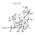
- a known art is shown in Fig. 8.
- a white light emitted by a light source 1 is guided through a condenser lens 3 and plane dichroic mirrors 2b1, 2b2, 2r1, and 2r2. Additionally, reflecting mirrors 5, 6, and 7 are provided, and liquid display display elements 9r, 9g, and 9b for each color are provided.
- a light which has passed through the projection lens 4 is projected on a screen.
- the plane dichroic mirrors 2b1 and 2b2 selectively reflect the wavelength band of blue and the plane dichroic mirrors 2r1 and 2r2 selectively reflect wavelength band of red.
- the system of Fig. 8 it is difficult to shorten the space between the light source 1 and each of the display elements 9r, 9g, and 9b because two dichroic mirrors 2b1, 2b2; 2r1, 2r2 in approximately the same size as that of each of the display elements 9r, 9g, and 9b are inserted between the condenser lens 3 and the display elements 9r, 9g, and 9b with the two dichroic mirrors at an angle of 45° to the optical axis of the condenser lens 3.
- the system has a problem that if the lights from the light source are not collimated well, lights are dispersed before they reach the display elements, so that a light amount to be effectively utilized is reduced.
- the system of Fig. 8 has the following problem: That is, the dichroic mirrors are used in an incident angle of approximately 45°, so that in this case, compared with the case in which a light is incident on the dichroic mirror perpendicularly, the degree of dependency on an incident angle of the spectral characteristic is great. Therefore, if the lights from the light source are not collimated well, color nonuniformity (nonuniformity of white balance) is likely to occur on the screen.
- Japanese Laid-Open Patent Publication No. 61-99118 discloses dichroic mirrors arranged in orthogonal X-type to be used as means for separating lights emitted by a single white light source into lights of the three primary colors of red, green, and blue and for synthesizing the image, of each of the three primary colors, formed by each display element.
- Japanese Laid-Open Patent Publication No. 50-10019 discloses "a projection type television receiver for optically synthesizing images, formed by three cathode ray tubes which emit three primary colors, through dichroic mirrors arranged in the orthogonal X-type".
- the dichroic mirrors arranged in the orthogonal X-type are composed of X-configured two pairs of dichroic mirrors formed by separating two dichroic mirrors into two, respectively although a dichroic mirror should essentially be jointless. Therefore, the spectral characteristic and the reflection angle thereof are likely to discontinue in jointed portions, so that seams appear on the display screen and hence the display quality degrades.
- the present invention is intended to provide a light source apparatus which is compact, separates a white light into lights of a plurality of colors, and increases the utilization ratio of a light emitted by a light source.
- a light source apparatus for separating a white light into lights of a plurality of colors, comprising: a white light source; at least two dichroic mirrors each of which selects a light with a part of a wavelength band from a visible light so as to transmit the light with the selected wavelength band in the visible light therethrough, and reflect a light with a wavelength band other than the selected wavelength band in the visible light, so that transparent wavelength bands of the mirrors are different from each other, the mirrors arranged in opposition to each other with respect to the white light source; and condenser lenses each of which is combined with each of the dichroic mirrors, wherein the light reflected by each of the dichroic mirrors is returned to the white light source.
- At least two dichroic mirrors are arranged in opposition thereto with respect to the white light source.
- Each dichroic mirror select the light with a part of the wavelength band of the visible light so as to transmit the selected light therethrough and reflect the light with the wavelength band other than the selected wavelength band. Since one aspect of the present invention is constructed so that the reflected light is returned to the white light source, the light reflected by one dichroic mirror is guided to the other dichroic mirror positioned on the other side. Thus, the utilization ratio of the light emitted by the white light source can be increased.
- the dichroic mirrors form at least a pair and separate the white light into the lights of a plurality of colors and the wavelength bands of lights transmitted through the dichroic mirrors are not overlapped with each other. In other words, the wavelength bands are separated from each other with an interval provided therebetween.
- a red-lights-transmitting dichroic mirror and a blue-lights-transmitting dichroic mirror are form a pair, and a green-lights-transmitting dichroic mirror and a mirror which reflects at least a green light form another pair.
- transmitting spectrum of each dichroic mirror may be designed independently, so that the dichroic mirrors forming the pair is capable of increasing the utilization ratio of lights emitted by the white light source and further, separating the white light into the lights of plurality of colors.
- the construction of the apparatus can be compact.
- the light source apparatus for separating a white light into lights of a plurality of colors as described in the previous aspect thereof, wherein the dichroic mirrors are spherically formed, each of the condenser lenses is arranged so that a distance between each of the condenser lenses and the white light source is longer than a distance between the corresponding dichroic mirror and the white light source.
- each of the dichroic mirrors is formed spherically, and the distance between the white light source and each of the condenser lenses is longer than that between the white light source and the corresponding dichroic mirror. Accordingly, each dichroic mirror separates the white light emitted by the white light source into the lights of a plurality of colors, and the condenser lens positioned for each color makes the separated lights parallel.
- the light source apparatus for separating a white light into lights of a plurality of colors as described in the first aspect thereof, wherein a surface of each of the condenser lenses is spherical on a side of the white light source and each of the dichroic mirrors is formed on the spherical surface of each of the condenser lenses.
- the condenser lens is spherically formed on the side of the white light source and the dichroic mirror is formed on this surface. Accordingly, the lights emitted by the white light source and separated into the lights of a plurality of colors by each dichroic mirror are immediately incident on the condenser lens and become parallel with each other.
- the light source apparatus for separating a white light into lights of a plurality of colors as described in the first aspect thereof, wherein each of the dichroic mirrors is arranged so that a distance between each of the dichroic mirrors and the white light source is longer than a distance between the corresponding condenser lens and the white light source, each of the dichroic mirrors being flatly formed and having a plane surface perpendicular to an optical axis of each of the condenser lenses.
- the flat dichroic mirrors are arranged so that the distance between the white light source and each of the dichroic mirrors is longer than that between the white light source and each of the condenser lenses, and each of the dichroic mirrors is perpendicular to the optical axis of the corresponding condenser lens. Accordingly, the white lights emitted by the white light source become parallel with each other by the condenser lenses, and thereafter, are incident on the dichroic mirrors. Lights which have passed through the dichroic mirrors travel rectilinearly as parallel lights. Lights which have been reflected by the dichroic mirrors travel back as parallel lights, then, returned to the white light source by the condenser lenses.
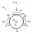
- Fig. 1 is a simplified sectional view showing a light source apparatus 10 according to one embodiment of the present invention.
- the light source apparatus 10 can be embodied in a projection color image display apparatus 11 shown in Figs. 2 through 4.
- a light source 12 of a white light comprising a halogen lamp, a xenon lamp or a metal halide lamp is substantially a point light source, and emits lights at least in the horizontal and vertical directions in Fig. 1.
- Each of dichroic mirrors 13R, 13G, and 13B selectively transmits each light with each wavelength band of red, green, and blue therethrough, thus reflecting a visible light except each selected light.
- Each wavelength band may partially superimpose with each other.
- These dichroic mirrors 13R, 13G, and 13B are spherically formed around a point 14, serving as the point light source of the white light source 12, at the center.
- These dichroic mirrors 13R, 13G, and 13B are bandpass or band-reflecting filters utilizing the interferences in a plurality of dielectric thin films of different refractive indexes.
- These dichroic mirrors 13R, 13G, and 13B have a multilayer thin film for carrying out a color separation, respectively as described above, and each minor thereof is so constructed that films of high and low refractive indecies are alternately deposited with each other with a film thickness being fundamentally integral multiples of 1/4 of a reference wavelength.
- a film characteristic having transparent and reflecting bands is obtained by alternately deposited films with each other in this manner.
- the dichroic mirrors 13R and 13B are symmetrical with respect to the point 14.
- the dichroic mirror 13G and a spherical reflecting mirror 13 are symmetrical with respect to the point 14.
- the condition of a multilayer thin film is set according to a multilayer thin film coating technique so that the red dichroic mirror 13R transmits a visible light of a wavelength longer than approximately 590nm, the blue dichroic mirror 13B transmits a visible light of a wavelength shorter than approximately 500nm, and the green dichroic mirror 13G transmits a visible light of a wavelength ranging from approximately 590nm to 500nm.
- the reflecting mirror 13 reflects a light of green toward the green dichroic mirror 13G and may not reflect lights of other wavelength bands.
- the light source 12 is so constructed that a light reflected by the reflecting mirror 13 is capable of being incident on the green dichroic mirror 13G to be transmitted therethrough.
- the point 14 serves as the emitting portion of the white light source 12.
- condenser lenses 15, 16, and 17 are arranged in correspondence with the dichroic mirrors 13R, 13G, and 13B, respectively.
- the red dichroic mirror 13R transmits a red component (R) therethrough, but reflects other components, so that they travel back to the light source 12, pass therethrough, and travel toward the blue dichroic mirror 13B.
- R red component
- a blue component and lights which have been emitted toward the blue dichroic mirror 13B pass therethrough.
- lights emitted by the single white light source 12 are separated into the red component R, the green component G, and the blue component B, thus being taken out radially in the three directions.
- each condenser lens consists of a plane convex lens, but a plurality of condenser lenses or aspherical lenses are used to increase an acceptance angle.
- the first advantage is that according to the known art shown in Fig. 8, a dichroic mirror of approximately the same size as that of the display element must be used while according to the above described embodiment, small spherical dichroic mirrors 13R, 13G, and 13B may be used providing that they cover the acceptance angle of the condenser lenses 15, 16, and 17.
- Another advantage is that the wavelength spectrum of a light of each color can be independently set for each of the dichroic mirrors 13R, 13G, and 13B. According to the conventional optical system shown in Fig.
- the red and blue components are separated from a white light and the rest becomes the light of green, so that the spectrum of the light of green is automatically decided by determining the spectra of lights of the red and blue components.
- the wavelength of each of the three dichroic mirrors 13R, 13G, and 13B can be independently selected, so that it is possible to set the spectra of the light of each color component to be slightly overlap with each other, thus resulting in the increase of brightness although the color reproduction range of a displayed image and chromaticness (namely, color purity) are lost to some extent.
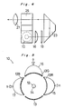
- Fig. 2 is a plan view showing the projection image display apparatus 11 which uses the light source apparatus 10 shown in Fig. 1.
- Fig. 3 is a front view showing the image display apparatus 11 of Fig. 2.
- Fig. 4 is a side view showing the image display apparatus 11, on the right side, shown in Fig. 2.
- each of the components R, G, and B is transmitted through each of liquid crystal display elements 18, 19, and 20 through each of the condenser lenses 15, 16, and 17, reflected by each of rectangular prisms 22, 23, and 24, synthesized by an orthogonal X-type dichroic mirror or a prism 26, and projected to a screen by a projection lens 27.
- a pair of plane mirrors may be used instead of each of the prisms 22, 23, and 24.
- the liquid crystal display elements 18, 19, and 20 may be provided halfway on the optical path of each of the rectangular prisms 22, 23, and 24 or each of the optical exit thereof.
- a field lens or a relay lens is provided in the vicinity of each of the display elements 18, 19, and 20 so as to converge lights which have passed through each of the display elements 18, 19, and 20.
- the red dichroic mirror 13R and the blue dichroic mirror 13B are positioned on either side of the light source 12, so that the passage wavelength band of these lights are not overlapped with each other.
- the desired red component (R) and the blue component (B) can be favorably taken out by this arrangement.
- the three dichroic mirrors 13R, 13G, and 13B which transmit the light with the wavelength band of each of red, green, and blue are formed on a spherical surface around the point 14, serving as the emitting portion of the white light source 12, and the two dichroic mirrors 13R and 13B of the three dichroic mirrors 13R, 13G, and 13B are positioned on either side of the white light source 12, so that lights emitted by the light source 12 are effectively utilized and a bright projected image can be displayed.
- the projection color image display apparatus which is compact, capable of utilizing lights emitted by the light source 12 which has a lot of luminous flux, and bright in the screen can be obtained.
- Fig. 5 is a simplified sectional view showing another embodiment of the present invention.
- the faces of the condenser lenses 15, 16, and 17 are spherical on the side of the light source 12 and the dichroic mirrors 13R, 13G, and 13B are formed on each of the surface thereof.
- each of the condenser lenses 15, 16, and 17 is formed as rotating elliptic face, and one of the focal points thereof is made to be coincident with each of the center of the spherical surface on which each of the dichroic mirrors 13R, 13G, and 13B is mounted, with the result that a known aplanatic lens is formed, and parallel lights are obtained by positioning the white light source 12 on the center of the spherical surface.
- the condenser lenses 15, 16, and 17, on which the dichroic mirrors 13R, 13G, and 13B which selectively transmits a light with each of the wavelength band of red, green, and blue are formed are symmetrically arranged with the white light source 12 at the center.
- the spherical mirror 13 is arranged in opposition to the dichroic mirror 13G which transmits the light with the wavelength of green.
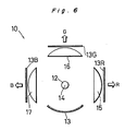
- Fig. 6 is a simplified sectional view showing a still another embodiment of the present invention.
- the condenser lenses 15, 16, and 17 are arranged between each of the dichroic mirrors 13R, 13G, and 13B and the white light source 12.
- Dispersed lights emitted by the white light source 12 become parallel with each other through each of the condenser lenses 15, 16, and 17, are then incident on each of the flat dichroic mirrors 13R, 13G, and 13B arranged perpendicularly to the optical axis of each of the condenser lenses 15, 16, and 17.
- lights of a desired wavelength pass through each dichroic mirror while lights of other wavelengths are reflected by each dichroic mirror, then travel back along the optical path thereof, pass through the white light source 12, are then incident on the other condenser lens positioned on the opposite side, thereafter are incident on the other dichroic mirror, with the result that the intensity of lights of the wavelength which has been taken out in the direction is increased.
- the embodiments relating to Figs. 5 and 6 can be used as the light source section of the projection image display apparatus as shown in Figs. 2 through 4.
- Fig. 7 is a simplified sectional view showing a further embodiment of the present invention. According to this embodiment, there are provided in a plane, including the sheet showing Fig. 7, the optical axis of a section in which a white light is separated into the three primary colors and the optical axis of a section in which the respective images of the three primary colors are synthesized.
- the section in which the white light is separated into the three primary colors includes the white light source 12, the condenser lenses 15, 16, and 17, the reflecting mirror 13, the dichroic mirrors 13R, 13G, and 13B, and the display elements 18, 19, and 20, and the section in which the respective images of the three primary colors are synthesized include two pairs of plane mirrors 32, 32a; and 34, 34a, two relay lenses 28 and 29, the orthogonal X-type dichroic mirror or the prism 26, and the projection lens 27.
- the relay lenses 28 and 29 are provided to compensate the difference of optical path lengths from the white light source 12 and prevent the illuminance of a light of each color from being unbalanced.
- the plane including the optical axis of the section in which the white light is separated into the three primary colors is parallel with the plane including the optical axis of the section in which the respective images of the three primary colors are synthesized, and these two planes are vertically spaced from each other in Figs. 3 and 4.
- a so-called two-storied construction it is possible to design the entire apparatus in a thin construction.
- the present invention can be embodied not only for a projection image display apparatus, but also for other uses.
- the utilization ratio of the lights emitted by the white light source can be increased by a compact construction and consequently, a display screen is bright when each of the embodiments of the present invention is embodied, for example, to carry out a projection display.
- the lights emitted by the white light source are incident on the dichroic mirror perpendicularly thereto. Therefore, a preferable advantage that a color nonuniformity, namely, the nonuniformity of a white balance does not occur can be obtained.
Landscapes
- Physics & Mathematics (AREA)
- General Physics & Mathematics (AREA)
- Optics & Photonics (AREA)
- Engineering & Computer Science (AREA)
- Multimedia (AREA)
- Signal Processing (AREA)
- Projection Apparatus (AREA)
- Video Image Reproduction Devices For Color Tv Systems (AREA)
Applications Claiming Priority (4)
| Application Number | Priority Date | Filing Date | Title |
|---|---|---|---|
| JP166024/89 | 1989-06-27 | ||
| JP16602489 | 1989-06-27 | ||
| JP342108/89 | 1989-12-27 | ||
| JP1342108A JPH0774862B2 (ja) | 1989-06-27 | 1989-12-27 | 白色光を複数色に分光する光源装置 |
Publications (3)
| Publication Number | Publication Date |
|---|---|
| EP0405953A2 true EP0405953A2 (fr) | 1991-01-02 |
| EP0405953A3 EP0405953A3 (en) | 1992-04-08 |
| EP0405953B1 EP0405953B1 (fr) | 1996-01-03 |
Family
ID=26490548
Family Applications (1)
| Application Number | Title | Priority Date | Filing Date |
|---|---|---|---|
| EP90307047A Expired - Lifetime EP0405953B1 (fr) | 1989-06-27 | 1990-06-27 | Appareil-source de lumière pour séparer la lumière blanche en composantes de différentes couleurs |
Country Status (3)
| Country | Link |
|---|---|
| US (1) | US5096280A (fr) |
| EP (1) | EP0405953B1 (fr) |
| DE (1) | DE69024545T2 (fr) |
Cited By (2)
| Publication number | Priority date | Publication date | Assignee | Title |
|---|---|---|---|---|
| EP0509630A3 (en) * | 1991-02-21 | 1993-07-14 | Eugene Dolgoff | A high efficiency light valve projection system |
| US5323301A (en) * | 1992-12-08 | 1994-06-21 | Robert Kaufman | Dimmable studio lighting device |
Families Citing this family (13)
| Publication number | Priority date | Publication date | Assignee | Title |
|---|---|---|---|---|
| EP0722253A3 (fr) * | 1995-01-10 | 1996-10-30 | Ibm | Arrangements pour des dispositifs d'affichage par projection utilisant des valves optiques en réflexion |
| US5644432A (en) * | 1995-01-17 | 1997-07-01 | Ibm Corporation | Three prism color separator |
| EP0734182B1 (fr) * | 1995-03-23 | 2001-01-17 | International Business Machines Corporation | Système optique efficace pour un écran de projection haute résolution employant des valves de lumière à réflexion |
| EP0734184B1 (fr) * | 1995-03-23 | 2001-01-17 | International Business Machines Corporation | Système optique efficace pour un écran de projection haute résolution employant des valves de lumière à réflexion |
| EP0734183B1 (fr) * | 1995-03-23 | 2001-01-17 | International Business Machines Corporation | Système optique efficace pour un écran de projection haute résolution employant des valves de lumière à réflexion |
| US5621486A (en) * | 1995-06-22 | 1997-04-15 | International Business Machines Corporation | Efficient optical system for a high resolution projection display employing reflection light valves |
| US6258447B1 (en) * | 1998-03-18 | 2001-07-10 | Southpac Trust Int'l, Inc. | Decorative shredded material |
| BR9915829A (pt) | 1998-11-02 | 2001-11-13 | Code 3 Inc | Luz de alerta para veìculo dotada de um elementodicróico |
| US6595669B2 (en) | 1998-11-02 | 2003-07-22 | Code 3, Inc. | Vehicular warning light having less apparent color when not energized |
| US7654695B1 (en) * | 2006-08-22 | 2010-02-02 | Avaya Inc. | Pigmented collar for bi-color light emitting diodes |
| CN109932858B (zh) * | 2017-12-18 | 2021-04-23 | 中强光电股份有限公司 | 照明系统与投影装置 |
| CN110095930A (zh) * | 2018-01-31 | 2019-08-06 | 中强光电股份有限公司 | 照明系统及投影装置 |
| US12068207B2 (en) | 2022-05-27 | 2024-08-20 | Taiwan Semiconductor Manufacturing Company, Ltd. | Simultaneous multi-bandwidth optical inspection of semiconductor devices |
Family Cites Families (11)
| Publication number | Priority date | Publication date | Assignee | Title |
|---|---|---|---|---|
| US2971051A (en) * | 1958-12-08 | 1961-02-07 | Frank G Back | Varifocal, long back-focal lens for color television |
| US3537789A (en) * | 1967-04-15 | 1970-11-03 | Fuji Photo Film Co Ltd | Light source for color printer |
| US3751133A (en) * | 1970-05-13 | 1973-08-07 | Minolta Camera Kk | Color separation optical system |
| US4003634A (en) * | 1974-08-12 | 1977-01-18 | Technical Operations Incorporated | Optical control assembly for a color design viewer |
| DE2723939C2 (de) * | 1977-05-24 | 1983-01-05 | Hans-Jörg Dr.rer.nat. 8520 Erlangen Albrecht | Vorrichtung zur Atemgasanalyse |
| JPS60179723A (ja) * | 1984-02-27 | 1985-09-13 | Sharp Corp | 液晶プロジエクシヨン装置 |
| US4850685A (en) * | 1984-10-22 | 1989-07-25 | Seiko Epson Corporation | Projection-type color display device |
| JPS6199118A (ja) * | 1984-10-22 | 1986-05-17 | Seiko Epson Corp | 投射型表示装置 |
| JPH0792561B2 (ja) * | 1986-07-08 | 1995-10-09 | 株式会社精工舎 | 投写式液晶表示装置 |
| EP0258927A3 (fr) * | 1986-08-22 | 1991-01-09 | North American Philips Corporation | Système d'affichage |
| JPH0642126B2 (ja) * | 1988-10-26 | 1994-06-01 | シャープ株式会社 | 投影型画像表示装置 |
-
1990
- 1990-06-25 US US07/542,926 patent/US5096280A/en not_active Expired - Lifetime
- 1990-06-27 DE DE69024545T patent/DE69024545T2/de not_active Expired - Fee Related
- 1990-06-27 EP EP90307047A patent/EP0405953B1/fr not_active Expired - Lifetime
Cited By (2)
| Publication number | Priority date | Publication date | Assignee | Title |
|---|---|---|---|---|
| EP0509630A3 (en) * | 1991-02-21 | 1993-07-14 | Eugene Dolgoff | A high efficiency light valve projection system |
| US5323301A (en) * | 1992-12-08 | 1994-06-21 | Robert Kaufman | Dimmable studio lighting device |
Also Published As
| Publication number | Publication date |
|---|---|
| DE69024545T2 (de) | 1996-06-27 |
| US5096280A (en) | 1992-03-17 |
| DE69024545D1 (de) | 1996-02-15 |
| EP0405953A3 (en) | 1992-04-08 |
| EP0405953B1 (fr) | 1996-01-03 |
Similar Documents
| Publication | Publication Date | Title |
|---|---|---|
| EP0545052B1 (fr) | Dispositif d'illumination et projecteur l'utilisant | |
| EP0773691B1 (fr) | Projecteur à cristaux liquides | |
| US5135300A (en) | Projection color display apparatus | |
| EP0287034A2 (fr) | Dispositif d'affichage à cristal liquide en couleurs par projection | |
| US5096280A (en) | Light source apparatus for separating white light into light components of a plurality of colors | |
| JPH0580290A (ja) | Lcdプロジエクターの光学システム | |
| EP0750822B1 (fr) | Combineur de faisceaux pour projecteur a affichage a cristaux liquides | |
| JPH0514249B2 (fr) | ||
| JPH0743658A (ja) | 投写型表示装置 | |
| US6176585B1 (en) | Projection apparatus | |
| US5488436A (en) | Liquid crystal projector | |
| JP3374452B2 (ja) | 投写型表示装置 | |
| JP2533672B2 (ja) | 投写型表示装置 | |
| JP2796653B2 (ja) | 投影型液晶表示装置 | |
| JPH10260474A (ja) | 背面投写型表示装置 | |
| US20050146786A1 (en) | Rear projection image display apparatus | |
| JPH0774862B2 (ja) | 白色光を複数色に分光する光源装置 | |
| JPH11174371A (ja) | 光学装置及び光学装置を備える表示装置 | |
| JP2802916B2 (ja) | Lcdプロジェクタ装置 | |
| KR930004643B1 (ko) | Cpt를 이용한 3패널 lcd 프로젝터 | |
| JPH0470827A (ja) | 投射型液晶表示装置 | |
| JP3615869B2 (ja) | 液晶投影装置およびこれを用いた投影表示システム | |
| JPH0643416A (ja) | 液晶表示装置 | |
| JPH09211750A (ja) | 液晶プロジェクタ | |
| JPH11150697A (ja) | 光学装置及びその光学装置を備える表示装置 |
Legal Events
| Date | Code | Title | Description |
|---|---|---|---|
| PUAI | Public reference made under article 153(3) epc to a published international application that has entered the european phase |
Free format text: ORIGINAL CODE: 0009012 |
|
| AK | Designated contracting states |
Kind code of ref document: A2 Designated state(s): DE FR GB NL |
|
| 17P | Request for examination filed |
Effective date: 19901214 |
|
| PUAL | Search report despatched |
Free format text: ORIGINAL CODE: 0009013 |
|
| AK | Designated contracting states |
Kind code of ref document: A3 Designated state(s): DE FR GB NL |
|
| 17Q | First examination report despatched |
Effective date: 19940603 |
|
| GRAA | (expected) grant |
Free format text: ORIGINAL CODE: 0009210 |
|
| AK | Designated contracting states |
Kind code of ref document: B1 Designated state(s): DE FR GB NL |
|
| REF | Corresponds to: |
Ref document number: 69024545 Country of ref document: DE Date of ref document: 19960215 |
|
| ET | Fr: translation filed | ||
| PLBE | No opposition filed within time limit |
Free format text: ORIGINAL CODE: 0009261 |
|
| STAA | Information on the status of an ep patent application or granted ep patent |
Free format text: STATUS: NO OPPOSITION FILED WITHIN TIME LIMIT |
|
| 26N | No opposition filed | ||
| PGFP | Annual fee paid to national office [announced via postgrant information from national office to epo] |
Ref country code: FR Payment date: 20010611 Year of fee payment: 12 |
|
| PGFP | Annual fee paid to national office [announced via postgrant information from national office to epo] |
Ref country code: DE Payment date: 20010618 Year of fee payment: 12 |
|
| PGFP | Annual fee paid to national office [announced via postgrant information from national office to epo] |
Ref country code: GB Payment date: 20010627 Year of fee payment: 12 |
|
| PGFP | Annual fee paid to national office [announced via postgrant information from national office to epo] |
Ref country code: NL Payment date: 20010628 Year of fee payment: 12 |
|
| REG | Reference to a national code |
Ref country code: GB Ref legal event code: IF02 |
|
| PG25 | Lapsed in a contracting state [announced via postgrant information from national office to epo] |
Ref country code: GB Free format text: LAPSE BECAUSE OF NON-PAYMENT OF DUE FEES Effective date: 20020627 |
|
| PG25 | Lapsed in a contracting state [announced via postgrant information from national office to epo] |
Ref country code: NL Free format text: LAPSE BECAUSE OF NON-PAYMENT OF DUE FEES Effective date: 20030101 Ref country code: DE Free format text: LAPSE BECAUSE OF NON-PAYMENT OF DUE FEES Effective date: 20030101 |
|
| GBPC | Gb: european patent ceased through non-payment of renewal fee |
Effective date: 20020627 |
|
| PG25 | Lapsed in a contracting state [announced via postgrant information from national office to epo] |
Ref country code: FR Free format text: LAPSE BECAUSE OF NON-PAYMENT OF DUE FEES Effective date: 20030228 |
|
| NLV4 | Nl: lapsed or anulled due to non-payment of the annual fee |
Effective date: 20030101 |
|
| REG | Reference to a national code |
Ref country code: FR Ref legal event code: ST |