EP0406054A1 - Vorrichtung zum Zugriff und zur Spurverfolgung für optische Platten - Google Patents
Vorrichtung zum Zugriff und zur Spurverfolgung für optische Platten Download PDFInfo
- Publication number
- EP0406054A1 EP0406054A1 EP90401673A EP90401673A EP0406054A1 EP 0406054 A1 EP0406054 A1 EP 0406054A1 EP 90401673 A EP90401673 A EP 90401673A EP 90401673 A EP90401673 A EP 90401673A EP 0406054 A1 EP0406054 A1 EP 0406054A1
- Authority
- EP
- European Patent Office
- Prior art keywords
- coil
- magnetic circuit
- track
- fixed
- core
- Prior art date
- Legal status (The legal status is an assumption and is not a legal conclusion. Google has not performed a legal analysis and makes no representation as to the accuracy of the status listed.)
- Granted
Links
- 230000003287 optical effect Effects 0.000 title claims abstract description 29
- 230000005855 radiation Effects 0.000 claims abstract description 6
- 239000004020 conductor Substances 0.000 claims description 13
- 239000000463 material Substances 0.000 claims description 2
- 239000007787 solid Substances 0.000 description 8
- 125000006850 spacer group Chemical group 0.000 description 3
- 230000001133 acceleration Effects 0.000 description 2
- 239000004809 Teflon Substances 0.000 description 1
- 229920006362 Teflon® Polymers 0.000 description 1
- XAGFODPZIPBFFR-UHFFFAOYSA-N aluminium Chemical compound [Al] XAGFODPZIPBFFR-UHFFFAOYSA-N 0.000 description 1
- 229910052782 aluminium Inorganic materials 0.000 description 1
- 238000006073 displacement reaction Methods 0.000 description 1
- 230000000694 effects Effects 0.000 description 1
- 238000004519 manufacturing process Methods 0.000 description 1
- 210000002445 nipple Anatomy 0.000 description 1
- 230000000284 resting effect Effects 0.000 description 1
- 238000005096 rolling process Methods 0.000 description 1
- 239000000725 suspension Substances 0.000 description 1
Images



Classifications
-
- G—PHYSICS
- G11—INFORMATION STORAGE
- G11B—INFORMATION STORAGE BASED ON RELATIVE MOVEMENT BETWEEN RECORD CARRIER AND TRANSDUCER
- G11B7/00—Recording or reproducing by optical means, e.g. recording using a thermal beam of optical radiation by modifying optical properties or the physical structure, reproducing using an optical beam at lower power by sensing optical properties; Record carriers therefor
- G11B7/12—Heads, e.g. forming of the optical beam spot or modulation of the optical beam
-
- G—PHYSICS
- G11—INFORMATION STORAGE
- G11B—INFORMATION STORAGE BASED ON RELATIVE MOVEMENT BETWEEN RECORD CARRIER AND TRANSDUCER
- G11B7/00—Recording or reproducing by optical means, e.g. recording using a thermal beam of optical radiation by modifying optical properties or the physical structure, reproducing using an optical beam at lower power by sensing optical properties; Record carriers therefor
- G11B7/08—Disposition or mounting of heads or light sources relatively to record carriers
- G11B7/085—Disposition or mounting of heads or light sources relatively to record carriers with provision for moving the light beam into, or out of, its operative position or across tracks, otherwise than during the transducing operation, e.g. for adjustment or preliminary positioning or track change or selection
- G11B7/0857—Arrangements for mechanically moving the whole head
- G11B7/08582—Sled-type positioners
Definitions
- the present invention relates to a device for accessing and controlling a track carried by a readable and / or optically recordable information medium by focused radiation such as an optical disc.
- these devices of the prior art generally comprise three separate motor devices.
- each coil being integral with an element of the optical head itself.
- the structure of the access and servo control device thus produced increases the unbalance of the mobile element and therefore the mass of the balancing counterweight, which has for main disadvantage of increasing the weight of the head.
- the subject of the present invention is a device for accessing and controlling a track carried by a readable information medium and / or optically recordable by focused radiation, this track forming regularly spaced towers on the support or with variable spacing, the towers forming a spiral, or being in the form of concentric circular elements, said device comprising an optical head with an optical axis orthogonal to the plane of the support, at least one fixed magnetic circuit comprising at least one core intersecting at all the turns of the track and the air gap of which forms a plane substantially perpendicular to the support, a first motor device allowing access and the radial tracking of the track constituted by at least a first coil mounted so as to move over the core of the magnetic circuit, and a second motor device allowing the focusing of the radiation on the track consisting of a second e coil cooperating with a magnetic circuit, characterized in that the optical head, the coil of the first motor device and the coil of the second motor device are rigidly fixed with each other so as to form a single compact mobile assembly moving
- the moving equipment is in one piece. It can therefore be produced in a very compact manner and consequently have a very low mass. This makes it possible to obtain very high accelerations and consequently very short access times.
- the device comprises two magnetic circuits each cooperating with a coil of the motor devices.
- the first coil is constituted by a cylindrical coil whose active conductors are directed along the optical axis of the optical head and the second coil is constituted by a boblne, preferably flat, whose active conductors are directed perpendicular to the optical axis.
- the second coil is rigidly fixed to the cylindrical coil by means of at least one support element such as spacers or rigid suspension elements.
- the access and control device further comprises at least one anti-pitching device.
- This anti-pitching device improves the angular stability between the moving element and the disc.
- the anti-pitching device consists of a rod fixed to one end of the movable assembly and comprising at its other end at least one means sliding in a slide parallel to the core of the first magnetic circuit.
- small pieces of material with a low coefficient of friction for example "teflon" are fixed to the access and radial servo coil and to the focusing coil
- FIG. 1 a device for accessing and controlling a track of an optical disc 1 rotating around an axis of rotation A in accordance with the present invention.
- this track is represented diagrammatically by grooves or towers 2 in FIG. 1.
- the access and control device is brought in front of the groove 2 and then the device is controlled in radial tracking so that it remains correctly positioned relative to the runway.
- the access and control device comprises at least one optical head 3 which will be described in more detail below, a first coil 4 for access and radial tracking and a second coil 5 for focus.
- This set forms a mobile crew.
- the head 3 is fixedly connected to the access and radial tracking coil as well as to the focusing coil 5.
- This mobile assembly is brought to move in translation in the air gaps of two fixed magnetic circuits.
- the central core 6 of the first fixed magnetic circuit has been shown. This core 6 intersects all the grooves or turns 2 of the disc 1 and extends over a length equal to at least the useful recording length increased by the length of the moving equipment, except the anti-pitching device. Indeed, the information is recorded conventionally according to a circular crown.
- the first magnetic circuit in association with the coil 4 forms the first motor device allowing access and tracking.
- the second magnetic circuit in association with the coil 5 forms the second motor device allowing focusing.
- the movable assembly is provided with an anti-pitching device 7.
- This device 7 consists, in the embodiment shown, of a slide 8 in which can slide a rod 9 fixed at one end to the movable assembly and carrying at its other end specific anti-pitching means whose shape corresponds to the shape of the slide 8 and which will be described in more detail below.
- the optical head 3 is more particularly constituted by a cylindrical element 30 carrying at its upper end a focusing objective 31 and at its lower end a deflection mirror 32 intended to reflect the beam coming from the laser source to the disc.
- the axis B of the head is placed orthogonally to the plane of the disc.
- This head 3 is fixed to a rigid support element 33 which is secured to the coil 4 of the motor device allowing access and radial tracking of the track.
- this coil 4 can be constituted by a cylindrical frame, of axis parallel to a radius of the disc, on which is wound at least one conductor, the turns of which are directed, in their active part, along the optical axis of the head, that is to say perpendicular to the axis of the cylindrical coil.
- the coil 4 is self-supporting, that is to say that it has no frame and its rigidity is ensured by the only bonding of the turns of its conductor.
- the coil 4 surrounds the central core 6 of the first magnetic circuit over which it is caused to slide.
- the first magnetic circuit comprises, in addition to the central core 6, right and left magnets 12 fixed on pole pieces 13.
- the pole pieces 13 and the central core 6 are secured together by bars end 14 which allow the closure of the field at the ends of this motor device.
- the field lines have the shape represented by the lines with arrows 15.
- the moving element is caused to move radially to the left or towards the right in FIG. 1 so as to position itself in front of a groove 2 to make the access and then to follow this groove as a function of the control signals sent.
- a coil 5 used to achieve focallsation.
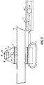
- This coil 5 is constituted by a flat coil of substantially elliptical shape in the mode of embodiment of FIG. 2.
- This coil comprises conductors directed perpendicular to the optical axis of the optical head 3.
- the lower part of the coil 5, namely the lower strands of the conductors 5 is positioned in the air gap of a second fixed magnetic circuit, the air gap 18 of which is parallel to the air gaps of the first magnetic circuit.
- This second magnetic circuit comprises a magnet 19 and two pole pieces 20, the assembly having a shape of C, in the example described.
- the magnetic field lines are represented by the reference 21.
- the coil 5 is traversed by an electric current I, there is creation of a force F directed in the vertical direction.
- a force F directed in the vertical direction This makes it possible to easily carry out the control in focusing.
- two parts 42 and 43 are fixed to the focusing coil 5. They guide this coil in its magnetic circuit. Associated with parts 40 and 41, they make it possible to limit the rolling movement of the moving assembly.
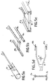
- the device of the present invention comprises an anti-pitching device 7 consisting of a rod 9 provided at its end with a ball 10 caused to slide in a slide 8 of substantially axis parallel to a radius of the disc.
- the anti-pitching device is constituted by an element with three branches 10 ′ which slides in a slide formed by a tube 8.
- the anti-pitching device consists of two cylindrical pins 10a, 10b connected by spacers to the rod 9 and brought to slide in two semi-cylindrical slides 8a, 8b.
- a spacer 10 ⁇ of rectangular section is fixed to the end of the rod 9 and is caused to slide in two slides 8′a, 8′b of section substantially U-shaped.
- the anti-pitching device consists of two branches which can be directed in the direction of the center of the recording-reading device and pass on each side of the motor axis A thus reducing the size of the device.
- the two slides 8 ⁇ a and 8 ⁇ b are similar to those of FIG. 5C.
- the two nipples 10 ⁇ a and 10 ⁇ b are of parallelepiped shape.
- This device provides both anti-pitch and anti-roll protection, as also allow the devices of Figures 5B and 5C. With these three devices, the anti-roll guide elements placed on either side of the focusing coil can be eliminated.
- Figure 6 shows in perspective the relative position of the coil 4 of access and radial control and a coil 5 'of focus. Only the coils are shown schematically to simplify the figure.
- the sides 4a and 4b are the active portions of the conductor or conductors of the coil 4.
- the parts 5′a and 5′b are the active portions of the conductor, or conductors of the coil 5 ′.
- This embodiment makes it possible to have only one magnetic circuit 13, 12, 6.
- the coil 5 can be constituted by a flat coil folded in a U so as to come to fit under the box 4 d 'access.
- the access and servo device in accordance with the present invention has the advantage of being in one piece and of being able to be produced in a very compact manner, which makes it possible to significantly reduce its weight.
- this device it was possible to eliminate the flexible connections between the coil 4 and the sliding elements, using the dynamic viscosity produced by the simultaneous movement of the first motor device and the second motor device.
Landscapes
- Physics & Mathematics (AREA)
- Optics & Photonics (AREA)
- Optical Recording Or Reproduction (AREA)
- Moving Of Heads (AREA)
- Moving Of The Head For Recording And Reproducing By Optical Means (AREA)
Applications Claiming Priority (2)
| Application Number | Priority Date | Filing Date | Title |
|---|---|---|---|
| FR8908800 | 1989-06-30 | ||
| FR8908800A FR2649238B1 (fr) | 1989-06-30 | 1989-06-30 | Dispositif d'acces et d'asservissement pour disque optique |
Publications (2)
| Publication Number | Publication Date |
|---|---|
| EP0406054A1 true EP0406054A1 (de) | 1991-01-02 |
| EP0406054B1 EP0406054B1 (de) | 1995-11-08 |
Family
ID=9383329
Family Applications (1)
| Application Number | Title | Priority Date | Filing Date |
|---|---|---|---|
| EP19900401673 Expired - Lifetime EP0406054B1 (de) | 1989-06-30 | 1990-06-15 | Vorrichtung zum Zugriff und zur Spurverfolgung für optische Platten |
Country Status (5)
| Country | Link |
|---|---|
| EP (1) | EP0406054B1 (de) |
| JP (1) | JPH03130931A (de) |
| CA (1) | CA2019630A1 (de) |
| DE (1) | DE69023397T2 (de) |
| FR (1) | FR2649238B1 (de) |
Cited By (2)
| Publication number | Priority date | Publication date | Assignee | Title |
|---|---|---|---|---|
| FR2683932A1 (fr) * | 1991-11-19 | 1993-05-21 | Atg Sa | Dispositif d'acces et de suivi de pistes pour disque optique. |
| EP0672289B1 (de) * | 1992-09-23 | 2000-07-12 | Seagate Technology, Inc. | Formfaktor 2,5 zoll plattenantrieb niedriger höhe |
Citations (2)
| Publication number | Priority date | Publication date | Assignee | Title |
|---|---|---|---|---|
| US4773062A (en) * | 1985-08-30 | 1988-09-20 | Pioneer Electronic Corporation | Optical information recording and reproducing apparatus including lens supporting mechanism employing cantilever springs |
| EP0287235A2 (de) * | 1987-04-15 | 1988-10-19 | Pioneer Electronic Corporation | Pick-up Steller für scheibenförmige Datenträger |
Family Cites Families (3)
| Publication number | Priority date | Publication date | Assignee | Title |
|---|---|---|---|---|
| JPS57200948A (en) * | 1981-06-02 | 1982-12-09 | Toshiba Corp | Optical information reader |
| JPS62223822A (ja) * | 1986-03-25 | 1987-10-01 | Mitsubishi Electric Corp | 対物レンズ駆動装置 |
| JPS6421728A (en) * | 1987-07-16 | 1989-01-25 | Oki Electric Ind Co Ltd | Optical head |
-
1989
- 1989-06-30 FR FR8908800A patent/FR2649238B1/fr not_active Expired - Fee Related
-
1990
- 1990-06-15 EP EP19900401673 patent/EP0406054B1/de not_active Expired - Lifetime
- 1990-06-15 DE DE1990623397 patent/DE69023397T2/de not_active Expired - Fee Related
- 1990-06-22 CA CA 2019630 patent/CA2019630A1/en not_active Abandoned
- 1990-06-29 JP JP17256290A patent/JPH03130931A/ja active Pending
Patent Citations (2)
| Publication number | Priority date | Publication date | Assignee | Title |
|---|---|---|---|---|
| US4773062A (en) * | 1985-08-30 | 1988-09-20 | Pioneer Electronic Corporation | Optical information recording and reproducing apparatus including lens supporting mechanism employing cantilever springs |
| EP0287235A2 (de) * | 1987-04-15 | 1988-10-19 | Pioneer Electronic Corporation | Pick-up Steller für scheibenförmige Datenträger |
Non-Patent Citations (2)
| Title |
|---|
| PATENT ABSTRACTS OF JAPAN vol. 12, no. 90 (P-679) 24 mars 1988, & JP-A-62 223822 (MITSUBISHI ELECTRIC CORPORATION) 1 octobre 1987, * |
| PATENT ABSTRACTS OF JAPAN vol. 7, no. 54 (P-180)(1199) 4 mars 1983, & JP-A-57 200948 (TOKYO SHIBAURA DENKI K.K.) 9 décembre 1982, * |
Cited By (4)
| Publication number | Priority date | Publication date | Assignee | Title |
|---|---|---|---|---|
| FR2683932A1 (fr) * | 1991-11-19 | 1993-05-21 | Atg Sa | Dispositif d'acces et de suivi de pistes pour disque optique. |
| EP0543707A1 (de) * | 1991-11-19 | 1993-05-26 | Art Tech Gigadisc Atg | Vorrichtung zum Spurzugriff und zur Spurverfolgung für optische Platte |
| US5420840A (en) * | 1991-11-19 | 1995-05-30 | Art Tech Gigadisc "Atg" | Separation type mono block optical head with tracking control achieved by a moveable mirror |
| EP0672289B1 (de) * | 1992-09-23 | 2000-07-12 | Seagate Technology, Inc. | Formfaktor 2,5 zoll plattenantrieb niedriger höhe |
Also Published As
| Publication number | Publication date |
|---|---|
| DE69023397D1 (de) | 1995-12-14 |
| EP0406054B1 (de) | 1995-11-08 |
| DE69023397T2 (de) | 1996-06-27 |
| JPH03130931A (ja) | 1991-06-04 |
| CA2019630A1 (en) | 1990-12-31 |
| FR2649238A1 (fr) | 1991-01-04 |
| FR2649238B1 (fr) | 1994-06-10 |
Similar Documents
| Publication | Publication Date | Title |
|---|---|---|
| EP0088010B1 (de) | Vorrichtung mit einem optischen Schreib/Lese-Kopf für eine optische Platte | |
| EP0088662B1 (de) | Vorrichtung zum Lesen und Schreiben einer optischen Platte mit Hilfe eines optischen Schreib-/Lesekopfes | |
| EP0012650B1 (de) | Vorrichtung mit Zugriff zu einer Spur eines optisch registrierbaren oder lesbaren Trägers und eine solche Vorrichtung enthaltendes optisches System | |
| EP0090683B1 (de) | Optischer Kopf in einer Schreib-Lese-Einrichtung für einen Informationsträger | |
| EP0055646B1 (de) | Optische Vorrichtung für den Zugriff zu Spuren eines beweglichen Informationsträgers | |
| FR2642530A1 (fr) | Mecanisme de focalisation et tete optique | |
| EP0033052A1 (de) | Optische Vorrichtung zur Aufnahme-Wiedergabe von Informationsträgern und optisches Speichersystem mit einer solchen Vorrichtung | |
| FR2652435A1 (fr) | Appareil optique de lecture/ecriture presentant de tres bonnes performances de suivi de piste. | |
| JPH08180453A (ja) | 高密度光記録方法及びその装置 | |
| US4793696A (en) | Method and apparatus for rapid focus control in an optical data storage device | |
| EP0180489B1 (de) | Gerät zur Aufnahme und Wiedergabe von Informationen auf Magnetband | |
| EP0406054B1 (de) | Vorrichtung zum Zugriff und zur Spurverfolgung für optische Platten | |
| FR2621411A1 (fr) | Dispositif asservi de lecture optique et d'ecriture magnetique d'un support d'informations | |
| US20030086141A1 (en) | Methods and apparatus for optical disk drives using optical scanning | |
| FR2519458A1 (fr) | Tete optique notamment pour la lecture d'une information | |
| EP0543707B1 (de) | Vorrichtung zum Spurzugriff und zur Spurverfolgung für optische Platte | |
| FR2615963A1 (fr) | Dispositif de commande du deplacement d'un objectif optique | |
| EP0036341B1 (de) | Optisches System zur Erzeugung spezieller Effekte auf Filmen | |
| US5410433A (en) | Access and follower control device for optical disk | |
| EP0516813B1 (de) | Servovorrichtung für optische platte | |
| JPH0519208B2 (de) | ||
| JP2560797Y2 (ja) | 光ヘッド装置 | |
| FR2621412A1 (fr) | Dispositif de lecture optique et d'ecriture magnetique d'un support d'informations | |
| JP2563768B2 (ja) | 対物レンズ駆動装置 | |
| JPH0644591A (ja) | 分離型光ヘッド |
Legal Events
| Date | Code | Title | Description |
|---|---|---|---|
| PUAI | Public reference made under article 153(3) epc to a published international application that has entered the european phase |
Free format text: ORIGINAL CODE: 0009012 |
|
| AK | Designated contracting states |
Kind code of ref document: A1 Designated state(s): DE GB IT NL SE |
|
| 17P | Request for examination filed |
Effective date: 19910122 |
|
| 17Q | First examination report despatched |
Effective date: 19930920 |
|
| GRAA | (expected) grant |
Free format text: ORIGINAL CODE: 0009210 |
|
| AK | Designated contracting states |
Kind code of ref document: B1 Designated state(s): DE GB IT NL SE |
|
| REF | Corresponds to: |
Ref document number: 69023397 Country of ref document: DE Date of ref document: 19951214 |
|
| ITF | It: translation for a ep patent filed | ||
| GBT | Gb: translation of ep patent filed (gb section 77(6)(a)/1977) |
Effective date: 19960122 |
|
| PLBE | No opposition filed within time limit |
Free format text: ORIGINAL CODE: 0009261 |
|
| STAA | Information on the status of an ep patent application or granted ep patent |
Free format text: STATUS: NO OPPOSITION FILED WITHIN TIME LIMIT |
|
| 26N | No opposition filed | ||
| PGFP | Annual fee paid to national office [announced via postgrant information from national office to epo] |
Ref country code: GB Payment date: 19991214 Year of fee payment: 10 |
|
| PGFP | Annual fee paid to national office [announced via postgrant information from national office to epo] |
Ref country code: SE Payment date: 19991217 Year of fee payment: 10 |
|
| PGFP | Annual fee paid to national office [announced via postgrant information from national office to epo] |
Ref country code: DE Payment date: 19991224 Year of fee payment: 10 |
|
| PGFP | Annual fee paid to national office [announced via postgrant information from national office to epo] |
Ref country code: NL Payment date: 19991231 Year of fee payment: 10 |
|
| PG25 | Lapsed in a contracting state [announced via postgrant information from national office to epo] |
Ref country code: GB Free format text: LAPSE BECAUSE OF NON-PAYMENT OF DUE FEES Effective date: 20000615 |
|
| PG25 | Lapsed in a contracting state [announced via postgrant information from national office to epo] |
Ref country code: SE Free format text: LAPSE BECAUSE OF NON-PAYMENT OF DUE FEES Effective date: 20000616 |
|
| PG25 | Lapsed in a contracting state [announced via postgrant information from national office to epo] |
Ref country code: NL Free format text: LAPSE BECAUSE OF NON-PAYMENT OF DUE FEES Effective date: 20010101 |
|
| GBPC | Gb: european patent ceased through non-payment of renewal fee |
Effective date: 20000615 |
|
| EUG | Se: european patent has lapsed |
Ref document number: 90401673.0 |
|
| NLV4 | Nl: lapsed or anulled due to non-payment of the annual fee |
Effective date: 20010101 |
|
| PG25 | Lapsed in a contracting state [announced via postgrant information from national office to epo] |
Ref country code: DE Free format text: LAPSE BECAUSE OF NON-PAYMENT OF DUE FEES Effective date: 20010403 |
|
| PG25 | Lapsed in a contracting state [announced via postgrant information from national office to epo] |
Ref country code: IT Free format text: LAPSE BECAUSE OF NON-PAYMENT OF DUE FEES Effective date: 20050615 |