EP0406090B1 - Einrichtung zur Wärmebehandlung eines erstarrbaren flüssigen Produktes und damit versehene Süsswareneinrichtung, wie eine Überzugs- und Abgussmaschine - Google Patents
Einrichtung zur Wärmebehandlung eines erstarrbaren flüssigen Produktes und damit versehene Süsswareneinrichtung, wie eine Überzugs- und Abgussmaschine Download PDFInfo
- Publication number
- EP0406090B1 EP0406090B1 EP19900401804 EP90401804A EP0406090B1 EP 0406090 B1 EP0406090 B1 EP 0406090B1 EP 19900401804 EP19900401804 EP 19900401804 EP 90401804 A EP90401804 A EP 90401804A EP 0406090 B1 EP0406090 B1 EP 0406090B1
- Authority
- EP
- European Patent Office
- Prior art keywords
- heat treatment
- fan
- treatment device
- chamber
- air
- Prior art date
- Legal status (The legal status is an assumption and is not a legal conclusion. Google has not performed a legal analysis and makes no representation as to the accuracy of the status listed.)
- Expired - Lifetime
Links
- 238000010438 heat treatment Methods 0.000 title claims abstract description 55
- 239000007788 liquid Substances 0.000 title claims description 14
- 238000000465 moulding Methods 0.000 title claims description 3
- 239000011248 coating agent Substances 0.000 title description 3
- 238000000576 coating method Methods 0.000 title description 3
- 235000019219 chocolate Nutrition 0.000 claims abstract description 19
- 239000012263 liquid product Substances 0.000 claims abstract description 5
- 239000000047 product Substances 0.000 claims abstract description 3
- 238000001816 cooling Methods 0.000 claims description 17
- 238000005485 electric heating Methods 0.000 claims description 3
- 230000008878 coupling Effects 0.000 claims description 2
- 238000010168 coupling process Methods 0.000 claims description 2
- 238000005859 coupling reaction Methods 0.000 claims description 2
- 238000004378 air conditioning Methods 0.000 claims 1
- 235000009508 confectionery Nutrition 0.000 abstract description 11
- 238000006073 displacement reaction Methods 0.000 abstract description 6
- 239000003570 air Substances 0.000 description 34
- 238000004891 communication Methods 0.000 description 5
- 238000002844 melting Methods 0.000 description 3
- 230000008018 melting Effects 0.000 description 3
- 239000012080 ambient air Substances 0.000 description 2
- 238000009434 installation Methods 0.000 description 2
- 238000000034 method Methods 0.000 description 2
- 230000000717 retained effect Effects 0.000 description 2
- 239000000523 sample Substances 0.000 description 2
- 238000005496 tempering Methods 0.000 description 2
- XLYOFNOQVPJJNP-UHFFFAOYSA-N water Substances O XLYOFNOQVPJJNP-UHFFFAOYSA-N 0.000 description 2
- 238000005452 bending Methods 0.000 description 1
- 230000005465 channeling Effects 0.000 description 1
- 238000002425 crystallisation Methods 0.000 description 1
- 230000008025 crystallization Effects 0.000 description 1
- 125000004122 cyclic group Chemical group 0.000 description 1
- 230000000694 effects Effects 0.000 description 1
- 230000004927 fusion Effects 0.000 description 1
- 238000005192 partition Methods 0.000 description 1
- 239000007787 solid Substances 0.000 description 1
- 238000007669 thermal treatment Methods 0.000 description 1
- 238000011144 upstream manufacturing Methods 0.000 description 1
Images
Classifications
-
- A—HUMAN NECESSITIES
- A23—FOODS OR FOODSTUFFS; TREATMENT THEREOF, NOT COVERED BY OTHER CLASSES
- A23G—COCOA; COCOA PRODUCTS, e.g. CHOCOLATE; SUBSTITUTES FOR COCOA OR COCOA PRODUCTS; CONFECTIONERY; CHEWING GUM; ICE-CREAM; PREPARATION THEREOF
- A23G3/00—Sweetmeats; Confectionery; Marzipan; Coated or filled products
- A23G3/02—Apparatus specially adapted for manufacture or treatment of sweetmeats or confectionery; Accessories therefor
- A23G3/20—Apparatus for coating or filling sweetmeats or confectionery
- A23G3/22—Apparatus for coating by casting of liquids
-
- A—HUMAN NECESSITIES
- A23—FOODS OR FOODSTUFFS; TREATMENT THEREOF, NOT COVERED BY OTHER CLASSES
- A23G—COCOA; COCOA PRODUCTS, e.g. CHOCOLATE; SUBSTITUTES FOR COCOA OR COCOA PRODUCTS; CONFECTIONERY; CHEWING GUM; ICE-CREAM; PREPARATION THEREOF
- A23G1/00—Cocoa; Cocoa products, e.g. chocolate; Substitutes therefor
- A23G1/04—Apparatus specially adapted for manufacture or treatment of cocoa or cocoa products
- A23G1/18—Apparatus for conditioning chocolate masses for moulding
Definitions
- the present invention relates to a device for the thermal treatment of a solidifiable liquid product, of the type comprising a receiving space for the latter, defined by a heat exchange wall with at least one surrounding enclosure in which air can be moved by a fan associated with a heating means.
- Such devices also called “tempering machines” are found in particular in installations for making confectionery articles, in particular wrappers, in which they then serve to subject the chocolate or other covering product to a cyclic heat treatment by circulation of hot air interspersed with cooling phases, optimizing its melting and crystallization.
- the ventilator draws air from the external environment to discharge it into the enclosure from which it emerges through an opening made at the other end thereof, after having been heated and circulated through its interior volume. This operation taking place continuously, often all day long, it inevitably results in a sharp rise in ambient temperature in the work room, particularly inconvenient for service personnel. Furthermore, the outside air being heated, it is impossible to reuse it for the cooling phase of the heat treatment process.
- the present invention proposes to remedy this drawback and, to do this, it relates to a heat treatment device of the type specified in the introduction, which is characterized in that the fan is inserted, with the heating means, to the inside a closed air displacement circuit, constituted at least in part by said enclosure and associated with a means of selective communication with the atmosphere designed to, in the active position, release an intake opening and a air discharge opening for said circuit, the intake opening then being in connection with the suction of the fan.
- the hot air therefore circulates in space closed without affecting the temperature of the outside environment, which allows the service personnel to maintain a healthy and pleasant working atmosphere.
- the air displacement circuit may have to be opened from time to time on the atmosphere, through the communication means, but only during the short cooling phase of the heat treatment or brief periods of re-establishment. pressure of the circuit, which of course cannot have consequences on the temperature of the environment.
- the cooling phase already reduced in duration by the fact that the outside air is not heated, can be further accelerated by the use of a cooling group placed opposite the air intake opening.
- the heating phases will advantageously be implemented using an electric heating resistor retained in the discharge of the fan.
- the invention also provides for the appearance of the fan, the heating means and the cooling unit in the form of a unit of the air conditioner type.
- said air movement circuit comprises in addition to the enclosure, an external section connected to the latter by its two ends and including the ventilator with its heating means, as well as the means of selective communication.
- said means of selective communication will, according to a simple design and easy implementation, preferably consist of a valve closing a light formed in a bend of a conduit constituting at least part of said outer section of the closed air movement circuit, this valve being pivotally mounted so that, in the open active position, it is applied against the interior wall of the elbow and is placed in a plane dividing the light into two openings communicating respectively, by the associated branches of the duct starting from the elbow, with the suction of the fan and the enclosure, in order to constitute said air intake and exhaust openings.
- a V-shaped deflector is also provided, the point of which is positioned facing the light, in the plane of opening of the valve, for, on each side of this valve in the open position, channeling perfectly the air sucked in by the fan through the intake opening and the air discharged through the exhaust opening respectively.
- the latter constitutes a second bend in the duct by connecting to the latter by its suction and to the enclosure by its discharge.
- said air displacement circuit is only constituted by the closed enclosure inside which the fan is installed in an eccentric position.
- the means of selective communication may advantageously be constituted by a shutter plate mounted sliding inside the enclosure, along a wall thereof, in which are formed said intake openings and discharge, this sheet itself having two lights which, in the active position of the sheet, are aligned respectively with the intake and discharge openings, the first at least of these lights being further arranged to ensure the coupling of the intake opening to the suction of the fan in said active position.
- the present invention also covers an installation for making confectionery articles, in particular by coating or molding, from a solidifiable confectionery liquid, such as melted chocolate, which is equipped with a heat treatment device, as defined above, whose space for receiving the confectionery liquid is constituted, at least in part, by a tank from which means are provided for raising said liquid to a dispenser overhanging a grid placed above the tank.
- a solidifiable confectionery liquid such as melted chocolate
- the means for raising the confectionery liquid consist of a pump, the suction of which is connected to said space for receiving liquid from the heat treatment device and the discharge of which is extended by a tube for supplying the liquid distributor.
- the invention further provides that the pump is housed inside the closed air movement circuit of the heat treatment device.
- the supply tube can advantageously be provided with a double envelope, the internal volume of which communicates with that of the closed air movement circuit of the heat treatment device, or of a closed identical air movement circuit arranged in an independent enclosure.
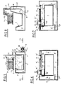
- FIG. 1 schematically illustrates a wrapper for confectionery sweets, of traditional general design, comprising in the low position a tank 1 for receiving a mass M of melted chocolate covering in which the lower part of a vertical rotating disc 2 plunges. At each rotation, this disc 2 is covered with a layer of chocolate, detached then in the upper part by a squeegee 3 deviating permanently from the melted chocolate towards a lateral distributor 4 in the form of a deflector. The latter, thus continuously supplied, then forms a vertical curtain R of melted chocolate through which the candies K to be coated pass, transported on a mobile endless grid 5 passing above the tank 1 which thus collects the excess melted chocolate .
- the tank 1 belongs more precisely to a device 6 for heat treatment of the mass M of melted chocolate, also visible in FIG. 2, in which its wall 7 is entirely surrounded by a closed enclosure 8 forming a double envelope, itself delimited by a front wall 9, a rear wall 10, two side walls 11,12, a bottom wall 13 and an upper wall 14 defining a flange around the open upper face of the tank 1.
- a bent conduit 16 opens into the enclosure 8, on its rear wall 10 and close to one 12 of its side walls.
- This conduit 16 is connected on the other side to the suction nozzle 17 of a fan 18, the discharge nozzle 19 of which opens into the enclosure 8, being welded to the rear wall 10 of the latter, not away from its second side wall 11.
- an electric heating resistor 20 is also retained inside the discharge nozzle 19 of the fan 18.
- FIG. 2 and its partial enlargement in FIG. 4 it can also be seen that, on its outer side, the elbow 21 of the conduit 16 is pierced with a light 22 closed by a valve 23 mounted pivoting about a vertical axis 24 located in the plane of symmetry P of the light 22.
- the positioning of the axis 24 and the dimensions of the valve 23 are such that, in its maximum open position illustrated by FIGS. 3 and 5, the latter, then placed in plane P, presses tightly against the entire inner wall of elbow 21.
- valve 23 partitions the lumen 22 and the elbow 21 into an air intake opening 25 connecting to the suction 17 of the fan 18 by the long branch 16a of the duct 16 and into a discharge opening air 26 communicating with the interior volume of the enclosure 8 by the short branch 16b of the same conduit.
- a deflector 27 in V shape is placed in front of the light 22, with its tip 27a directed towards it and positioned in its plane of symmetry P, for, in the open position of the valve 23, illustrated by Figures 3 and 5, extend this last, by its wings 27b and 27c, respectively upstream of the intake opening 25 and the discharge opening 26.
- a cooling group here constituted by a network of cooling tubes 28 is installed opposite at the opening of admission 25.
- the device which has just been described is controlled by an automatic control regulator allowing the implementation of a heat treatment or "tempering" procedure, which takes place as follows.
- a first phase called chocolate melting
- the enclosure 8 and the duct 16 being filled with ambient air and the valve 23 closed (FIGS. 2 and 4)
- the resistor 20 is activated and the fan 18 is put into service.
- the air which gradually heats up in contact with the resistor 20, is thus circulated in the direction of the arrows A in FIG. 2, inside a closed circuit constituted by the enclosure 8 and the conduit 16
- the air thus heated raises the temperature of the chocolate present in the latter, initially in the solid state.
- the electrical supply of the resistor 20 is cut off by a probe 29 installed inside the enclosure 8.
- the valve 23 is firstly opened and placed in its position in FIGS. 3 and 5, and the cooling group 28 is put into service. Consequently, the fan 18, still in operation, sucks through the latter, the intake opening 25 and the long branch 16a of the duct 16, an air stream channeled at the start by the wing 27b of the deflector.
- the air thus cooled and discharged into the enclosure 8 by the fan 18 follows the arrowed path B before exiting into the atmosphere through the short branch 16b of the conduit, the discharge opening 26 and along the second branch 27c of the deflector 27.
- the probe 29 reactivates the heating resistor 20 and the valve 23 is simultaneously closed, to activate work of the third phase of the processing, called raising and maintaining the temperature of the melted chocolate (up to approximately 31 ° C.), which continues throughout the period of use of the wrapper.
- this three-phase heat treatment has the effect of "crystallizing" the chocolate, that is to say of giving it the best consistency possible for a high quality coating.
- the first and third heating phases take place in a closed circuit and therefore without altering the temperature of the working room, even if from time to time the valve 23 should be opened slightly to maintain sufficient pressure inside the enclosure 8.
- the valve 23 opens fully only during the second cooling phase which is of course without consequence on the comfort of service personnel.
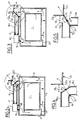
- the second embodiment of the heat treatment device according to the invention differs from the first by the simple fact that the fan 18 ′, with its heating resistor 20 ′, is here entirely housed inside of the enclosure 8 ', in a lower rear corner thereof with its outlet 19 directed towards its nearest side wall 11'.
- the enclosure 8 ' defines here by itself, around the tank 1, the air displacement circuit.
- the rear wall 10 'of the enclosure 8' is pierced with two circular openings, one 25 'located opposite the suction nozzle 17' of the fan 18 'and the second 26 'formed at the other end of the wall 10'.
- These openings 25 ′, 26 ′, each surrounded by a sleeve 30 or 31 projecting inside the wall 10 ′, are, during the heating phase of the device, closed by a sliding vertical sheet 32 which is inserted tightly between the suction nozzle 17 'of the fan 18' and the sleeve 30 of the opening 25 'located opposite.
- the sheet 32 is itself provided with two circular openings 33, 34 which, following a horizontal sliding symbolized by the arrow Y in FIG.
- the opening 25 ′ constitutes the opening for the admission of ambient air optionally cooled by cooling tubes 35, this opening being connected to the suction 17 ′ of the fan 18 ′, while the second opening 26 ′ constitutes the opening for evacuating the air having circulated through the enclosure 8 ′.
- FIG. 8 represents a variant of the wrapper of FIG. 1, in which the rotary disc 2 has been replaced by a pump 36, the suction of which is connected to the bottom of the tank 1, by a conduit 37, and the delivery is extended by a vertical tube 38 for raising the chocolate, ending above the dispenser 4 while bending at 39 towards the latter.
- the pump 36 is housed in the rear part 40, oversized in width and in height, of the enclosure 8 and the vertical tube 38 is, on its section external to said rear part, provided with a double envelope 41 welded to the upper wall 42 thereof.
- the annular space delimited by this double envelope of the tube 38 communicates with the interior volume of the enclosure 8 and, at its free end 43, opens onto the atmosphere. Thanks to these arrangements, it is advantageous to use the hot air present most of the time inside the enclosure, to keep the chocolate in fusion inside the pump 36 and the tube 38.
Landscapes
- Life Sciences & Earth Sciences (AREA)
- Chemical & Material Sciences (AREA)
- Engineering & Computer Science (AREA)
- Food Science & Technology (AREA)
- Polymers & Plastics (AREA)
- Confectionery (AREA)
- Formation And Processing Of Food Products (AREA)
- Beans For Foods Or Fodder (AREA)
- General Preparation And Processing Of Foods (AREA)
- Application Of Or Painting With Fluid Materials (AREA)
- Processing And Handling Of Plastics And Other Materials For Molding In General (AREA)
- Heating, Cooling, Or Curing Plastics Or The Like In General (AREA)
- Manufacturing And Processing Devices For Dough (AREA)
Claims (13)
- Vorrichtung zur Wärmebehandlung eines erstarrbaren flüssigen Produkts, insbesondere eines verflüssigten Süßwarenprodukts wie geschmolzener Schokolade, des Typs, der einen Aufnahmeraum (1) des genannten flüssigen Produkts (M) enthält, begrenzt durch eine Wärmetauscherwand (7) mit wenigstens einer Umschließung (8, 8'), in der Luft bewegt werden kann mittels eines mit einer Heizeinrichtung (20) verbundenen Ventilators (18, 18'), dadurch gekennzeichnet,
daß der Ventilator (18, 18') mit der Heizeinrichtung (20) eingebaut ist in das Innere eines geschlossenen Luftstromkreises, wenigstens teilweise gebildet aus der genannten Umschließung (8, 8') und verbunden ist mit einer wahlweise verstellbaren Verbindungseinrichtung (23, 32) mit der Außenluft, so beschaffen, daß sie in aktiver Stellung eine Lufteinlaßöffnung (25, 25') und eine Luftauslaßöffnung (26, 26') freigibt, wobei die Einlaßöffnung dann in Verbindung steht mit der Ansaugung (17, 17') des Ventilators (18, 18'). - Wärmebehandlungsvorrichtung nach Anspruch 1, dadurch gekennzeichnet, daß der genannte Luftstromkreis außer der Umschließung (8) einen Außenteilabschnitt aufweist, der an diese mit seinen beiden Enden angeschlossen ist und den Ventilator (18) und seine Heizeinrichtung enthält, sowie die wahlweise verstellbare Verbindungseinrichtung (23).
- Wärmebehandlungsvorrichtung nach Anspruch 2, dadurch gekennzeichnet, daß der genannte Außenteilabschnitt eine Leitung (16) enthält, die einen Krümmer (21) aufweist, in dem ein Luftdurchlaß (22) angebracht ist, verschlossen durch eine Klappe (23), welche die genannte wahlweise verstellbare Verbindungseinrichtung bildet, wobei die Klappe schwenkbar montiert ist, um sich in der aktiven offenen Position der Innenwand des Krümmers (21) anzupassen in einer Ebene (P), die den Luftdurchlaß (22) in zwei Öffnungen (25, 26) unterteilt, die durch die verbundenen Zweige (16a, 16b) der Leitung (16), ausgehend vom Krümmer (21), mit der Ansaugung (17) des Ventilators (18) bzw. der Umschließung (8) kommunizieren, um die genannten Öffnungen für Einlaß und Auslaß zu bilden.
- Wärmebehandlungsvorrichtung nach Anspruch 3, dadurch gekennzeichnet, daß sie ein V-förmiges Umlenkblech (27) enthält, dessen Kante vor dem Durchlaß (22) angebracht ist in der Öffnungsebene (P) der Klappe (23).
- Wärmebehandlungsvorrichtung nach Anspruch 3 oder 4, dadurch gekennzeichnet, daß der Ventilator (18) einen zweiten Krümmer der Leitung (16) bildet, indem er an letztere mit seiner Saugseite (17) angeschlossen ist, und an die Umschließung (8) mit seiner Druckseite (19).
- Wärmebehandlungsvorrichtung nach Anspruch 1, dadurch gekennzeichnet, daß der Luftstromkreis nur aus der geschlossenen Umschließung (8') besteht, in deren Innerem der Ventilator (18') in einer exzentrischen Position installiert ist.
- Wärmebehandlungsvorrichtung nach Anspruch 6, dadurch gekennzeichnet, daß die wahlweise verstellbare Verbindungseinrichtung aus einem Verschlußblech (32) besteht, das verschiebbar im Innern der Umschließung angebracht ist, längs einer Wand (10') von dieser, in der die genannten Öffnungen für Einlaß (25') und Auslaß (26') angebracht sind, wobei dieses Blech (32) selbst zwei Durchlässe (33, 34) aufweist, die in der aktiven Position des Blechs mit den Öffnungen für Einlaß bzw. Auslaß fluchten, wobei wenigstens der erste dieser Durchlässe (33) überdies eingerichtet ist, um in der genannten aktiven Stellung die Kupplung der Einlaßöffnung (25') mit der Ansaugung (17') des Ventilators (18) zu gewährleisten.
- Wärmebehandlungsvorrichtung nach irgendeinem der Ansprüche 1 bis 7, dadurch gekennzeichnet, daß sie eine Kühlgruppe (28, 35) enthält, die vor der Ansaugöffnung (25, 25') angebracht ist.
- Wärmebehandlungsvorrichtung nach irgendeinem der Ansprüche 1 bis 8, dadurch gekennzeichnet, daß die Heizeinrichtung aus einem heizenden elektrischen Widerstand (20) besteht, angebracht auf der Druckseite (18, 18') des Ventilators (17, 17').
- Wärmebehandlungsvorrichtung nach irgendeinem der Ansprüche 1 bis 7, dadurch gekennzeichnet, daß der Ventilator (17, 17') und die Heizeinrichtung zusammengefaßt sind zu einer Einheit des Typs Klimagerät mit integrierter Kühlgruppe.
- Anlage zum Herstellen von Süßwaren, vor allem durch Überzug oder Guß, aus einer erstarrbaren Süßwarenflüssigkeit, wie etwa geschmolzene Schokolade, wobei diese Anlage einen Verteiler (4) für Süßwarenflüssigkeit enthält, der über einem Gitter (5) hängt, das über einer Wanne (1) angebracht ist, die zu einer Wärmebehandlungsvorrichtung (6) einer Süßwarenflüssigkeits-Hauptmasse (M) gehört, wo Mittel (2, 36, 38) vorgesehen sind, um die genannte Flüssigkeit bis zum Verteiler anzuheben, dadurch gekennzeichnet, daß die Wärmebehandlungsvorrichtung (6) gebildet wird durch die in irgendeinem der Ansprüche 1 bis 10 definierte, deren Aufnahmeraum für die Flüssigkeit, zumindest teilweise, durch die Wanne (1) gebildet wird.
- Anlage nach Anspruch 11, dadurch gekennzeichnet, daß die Hebemittel für die Süßwarenflüssigkeit bestehen aus einer Pumpe (36), deren Ansaugung an dem genanntem Flüssigkeits-Aufnahmeraum (1) der Wärmebehandlungsvorrichtung (6) angeschlossen ist und deren Druckseite verlängert wird durch ein Versorgungsrohr (38) für den Verteiler der Süßwarenflüssigkeit, dadurch gekennzeichnet, daß die genannte Pumpe (36) im Innern des geschlossenen Luftstromkreises der Wärmebehandlungsvorrichtung (6) untergebracht ist.
- Anlage nach Anspruch 12, dadurch gekennzeichnet, daß das genannte Versorgungsrohr (38) mit einer doppelten Hülle (41) versehen ist, deren Innenraum mit dem des geschlossenen Luftstromkreises der Wärmebehandlungsvorrichtung (6) oder mit einem in einem unabhängigen Behälter untergebrachten identischen geschlossenen Luftstromkreis kommuniziert.
Priority Applications (1)
| Application Number | Priority Date | Filing Date | Title |
|---|---|---|---|
| AT90401804T ATE89127T1 (de) | 1989-06-28 | 1990-06-25 | Einrichtung zur waermebehandlung eines erstarrbaren fluessigen produktes und damit versehene suesswareneinrichtung, wie eine ueberzugs- und abgussmaschine. |
Applications Claiming Priority (2)
| Application Number | Priority Date | Filing Date | Title |
|---|---|---|---|
| FR8908631 | 1989-06-28 | ||
| FR8908631A FR2648990B1 (fr) | 1989-06-28 | 1989-06-28 | Dispositif pour le traitement thermique d'un produit liquide solidifiable et installation de confection d'articles de confiserie, telle qu'enrobeuse ou mouleuse, equipee d'un dispositif de ce type |
Publications (2)
| Publication Number | Publication Date |
|---|---|
| EP0406090A1 EP0406090A1 (de) | 1991-01-02 |
| EP0406090B1 true EP0406090B1 (de) | 1993-05-12 |
Family
ID=9383220
Family Applications (1)
| Application Number | Title | Priority Date | Filing Date |
|---|---|---|---|
| EP19900401804 Expired - Lifetime EP0406090B1 (de) | 1989-06-28 | 1990-06-25 | Einrichtung zur Wärmebehandlung eines erstarrbaren flüssigen Produktes und damit versehene Süsswareneinrichtung, wie eine Überzugs- und Abgussmaschine |
Country Status (5)
| Country | Link |
|---|---|
| EP (1) | EP0406090B1 (de) |
| AT (1) | ATE89127T1 (de) |
| DE (1) | DE69001585T2 (de) |
| ES (1) | ES2041512T3 (de) |
| FR (1) | FR2648990B1 (de) |
Families Citing this family (1)
| Publication number | Priority date | Publication date | Assignee | Title |
|---|---|---|---|---|
| US7293525B2 (en) * | 2003-08-29 | 2007-11-13 | Hdn Development Corporation | Method and apparatus for applying glaze or other coatings to food products |
Family Cites Families (3)
| Publication number | Priority date | Publication date | Assignee | Title |
|---|---|---|---|---|
| FR580702A (fr) * | 1924-03-28 | 1924-11-14 | Anciens Ets Savy | Machine pour l'enrobage des bonbons et biscuits avec du chocolat |
| GB1122461A (en) * | 1965-01-29 | 1968-08-07 | Greer J W Co | Improved method of conditioning an edible fatty substance |
| DE2322838A1 (de) * | 1973-05-07 | 1974-11-28 | Sollich Ohg | Verfahren zum temperieren von kakaobutterhaltigen massen, insbesondere von schokoladenmassen, sowie vorrichtung zur durchfuehrung des verfahrens |
-
1989
- 1989-06-28 FR FR8908631A patent/FR2648990B1/fr not_active Expired - Fee Related
-
1990
- 1990-06-25 ES ES199090401804T patent/ES2041512T3/es not_active Expired - Lifetime
- 1990-06-25 EP EP19900401804 patent/EP0406090B1/de not_active Expired - Lifetime
- 1990-06-25 AT AT90401804T patent/ATE89127T1/de not_active IP Right Cessation
- 1990-06-25 DE DE90401804T patent/DE69001585T2/de not_active Expired - Fee Related
Also Published As
| Publication number | Publication date |
|---|---|
| DE69001585D1 (de) | 1993-06-17 |
| EP0406090A1 (de) | 1991-01-02 |
| ES2041512T3 (es) | 1993-11-16 |
| DE69001585T2 (de) | 1993-10-28 |
| ATE89127T1 (de) | 1993-05-15 |
| FR2648990A1 (fr) | 1991-01-04 |
| FR2648990B1 (fr) | 1991-10-11 |
Similar Documents
| Publication | Publication Date | Title |
|---|---|---|
| EP0235061B1 (de) | Indirekt erhitzter Bäckereiofen mit Backwagen und Verfahren zur Dampfabfuhr | |
| BE1001974A5 (fr) | Appareil de cuisson d'aliments. | |
| EP0198749B1 (de) | Haushaltsgerät zum Spenden eines wasseraufsaugenden Pulvers | |
| EP0910269A1 (de) | Kondensiervorrichtung für kochdämpfe und kochgerät mit einer solchen vorrichtung | |
| FR2564752A1 (fr) | Appareil de peinture et procede pour delivrer un liquide, notamment de la peinture, d'une source d'approvisionnement a un support d'application, mur, plafond ou analogue | |
| FR2726433A1 (fr) | Four a cuisson continue de produits de boulangerie, viennoiserie, patisserie et analogue | |
| FR2748519A1 (fr) | Dispositif de refroidissement d'un moteur avec reservoir de fluide thermiquement isole | |
| EP0406090B1 (de) | Einrichtung zur Wärmebehandlung eines erstarrbaren flüssigen Produktes und damit versehene Süsswareneinrichtung, wie eine Überzugs- und Abgussmaschine | |
| EP1209420B1 (de) | Dampfauslass für Dampfkochgeräte | |
| FR2888632A1 (fr) | Four a cavite ventilee | |
| EP0371845B1 (de) | Gesteuerter Gärraum für das Bäcker- und Konditorgewerbe | |
| FR2458761A1 (fr) | Four perfectionne a circulation d'air pour chauffer des aliments | |
| EP0115971B1 (de) | Maschine zum Herstellen von waffelförmigen kulinarischen Spezialitäten | |
| WO2002028190A1 (fr) | Procede et machine pour garnir des sandwichs | |
| EP2407031B1 (de) | Vorrichtung zum Formen von Hohlschalen durch thermisches Erstarren | |
| EP0343059B1 (de) | Verfahren und Vorrichtung zum Einnehmen einer Flüssigkeit, wie Quellwasser | |
| EP4299825A1 (de) | Elektrisches haushaltsgerät zum bügeln und/oder glätten mit einer vorrichtung zum zurückhalten von dampfgetragenen kalkpartikeln | |
| FR2752456A1 (fr) | Dispositif pour le transfert regule de frigories entre une reserve et une enceinte de conservation | |
| FR2637966A1 (fr) | Dispositif de conditionnement d'air interieur | |
| FR2593690A1 (fr) | Meuble pour la maturation, la conservation et la presentation de produits alimentaires en atmosphere controlee, tels que notamment des saucissons | |
| FR2976455A1 (fr) | Four de cuisson a generation de vapeur d'eau | |
| EP1688071A1 (de) | System zum Kochen und zum Abkühlen von Nahrungsmitteln durch Eintauchen in ein flüssiges Wärmeübertragungsmittel | |
| FR2754144A1 (fr) | Four de cuisson modulaire et procede de cuisson d'un produit alimentaire | |
| EP1881942A1 (de) | Spendevorrichtung zur bereitstellung von gekühltem wasser | |
| EP1775216A1 (de) | Selbstreinigender Wagen zum Transport und Verteilen von Essen auf Tabletts |
Legal Events
| Date | Code | Title | Description |
|---|---|---|---|
| PUAI | Public reference made under article 153(3) epc to a published international application that has entered the european phase |
Free format text: ORIGINAL CODE: 0009012 |
|
| AK | Designated contracting states |
Kind code of ref document: A1 Designated state(s): AT BE CH DE DK ES GB GR IT LI LU NL SE |
|
| 17P | Request for examination filed |
Effective date: 19910610 |
|
| 17Q | First examination report despatched |
Effective date: 19920921 |
|
| GRAA | (expected) grant |
Free format text: ORIGINAL CODE: 0009210 |
|
| AK | Designated contracting states |
Kind code of ref document: B1 Designated state(s): AT BE CH DE DK ES GB GR IT LI LU NL SE |
|
| PG25 | Lapsed in a contracting state [announced via postgrant information from national office to epo] |
Ref country code: SE Effective date: 19930512 Ref country code: NL Effective date: 19930512 Ref country code: GR Free format text: LAPSE BECAUSE OF FAILURE TO SUBMIT A TRANSLATION OF THE DESCRIPTION OR TO PAY THE FEE WITHIN THE PRESCRIBED TIME-LIMIT Effective date: 19930512 Ref country code: DK Effective date: 19930512 Ref country code: AT Effective date: 19930512 |
|
| REF | Corresponds to: |
Ref document number: 89127 Country of ref document: AT Date of ref document: 19930515 Kind code of ref document: T |
|
| RAP4 | Party data changed (patent owner data changed or rights of a patent transferred) |
Owner name: SAVY ET GOISEAU |
|
| REF | Corresponds to: |
Ref document number: 69001585 Country of ref document: DE Date of ref document: 19930617 |
|
| PG25 | Lapsed in a contracting state [announced via postgrant information from national office to epo] |
Ref country code: LU Free format text: LAPSE BECAUSE OF NON-PAYMENT OF DUE FEES Effective date: 19930630 Ref country code: LI Effective date: 19930630 Ref country code: CH Effective date: 19930630 |
|
| ITF | It: translation for a ep patent filed | ||
| GBT | Gb: translation of ep patent filed (gb section 77(6)(a)/1977) |
Effective date: 19930823 |
|
| NLV1 | Nl: lapsed or annulled due to failure to fulfill the requirements of art. 29p and 29m of the patents act | ||
| REG | Reference to a national code |
Ref country code: ES Ref legal event code: FG2A Ref document number: 2041512 Country of ref document: ES Kind code of ref document: T3 |
|
| REG | Reference to a national code |
Ref country code: CH Ref legal event code: PL |
|
| PGFP | Annual fee paid to national office [announced via postgrant information from national office to epo] |
Ref country code: ES Payment date: 19960613 Year of fee payment: 7 |
|
| PGFP | Annual fee paid to national office [announced via postgrant information from national office to epo] |
Ref country code: GB Payment date: 19960618 Year of fee payment: 7 |
|
| PGFP | Annual fee paid to national office [announced via postgrant information from national office to epo] |
Ref country code: DE Payment date: 19970623 Year of fee payment: 8 |
|
| PG25 | Lapsed in a contracting state [announced via postgrant information from national office to epo] |
Ref country code: GB Free format text: LAPSE BECAUSE OF NON-PAYMENT OF DUE FEES Effective date: 19970625 |
|
| PG25 | Lapsed in a contracting state [announced via postgrant information from national office to epo] |
Ref country code: ES Free format text: LAPSE BECAUSE OF EXPIRATION OF PROTECTION Effective date: 19970626 |
|
| PGFP | Annual fee paid to national office [announced via postgrant information from national office to epo] |
Ref country code: BE Payment date: 19970711 Year of fee payment: 8 |
|
| GBPC | Gb: european patent ceased through non-payment of renewal fee |
Effective date: 19970625 |
|
| PG25 | Lapsed in a contracting state [announced via postgrant information from national office to epo] |
Ref country code: BE Free format text: LAPSE BECAUSE OF NON-PAYMENT OF DUE FEES Effective date: 19980630 |
|
| BERE | Be: lapsed |
Owner name: SOC. DE MECANIQUE GENERALE GOISEAU GUITTOT S.A. Effective date: 19980630 |
|
| PG25 | Lapsed in a contracting state [announced via postgrant information from national office to epo] |
Ref country code: DE Free format text: LAPSE BECAUSE OF NON-PAYMENT OF DUE FEES Effective date: 19990401 |
|
| REG | Reference to a national code |
Ref country code: ES Ref legal event code: FD2A Effective date: 20010201 |
|
| PG25 | Lapsed in a contracting state [announced via postgrant information from national office to epo] |
Ref country code: IT Free format text: LAPSE BECAUSE OF NON-PAYMENT OF DUE FEES;WARNING: LAPSES OF ITALIAN PATENTS WITH EFFECTIVE DATE BEFORE 2007 MAY HAVE OCCURRED AT ANY TIME BEFORE 2007. THE CORRECT EFFECTIVE DATE MAY BE DIFFERENT FROM THE ONE RECORDED. Effective date: 20050625 |
|
| PLBE | No opposition filed within time limit |
Free format text: ORIGINAL CODE: 0009261 |
|
| STAA | Information on the status of an ep patent application or granted ep patent |
Free format text: STATUS: NO OPPOSITION FILED WITHIN TIME LIMIT |