EP0406118A2 - Einrichtung und Verfahren zum Reduzieren von Radiofrequenz-Geräusch - Google Patents
Einrichtung und Verfahren zum Reduzieren von Radiofrequenz-Geräusch Download PDFInfo
- Publication number
- EP0406118A2 EP0406118A2 EP90401874A EP90401874A EP0406118A2 EP 0406118 A2 EP0406118 A2 EP 0406118A2 EP 90401874 A EP90401874 A EP 90401874A EP 90401874 A EP90401874 A EP 90401874A EP 0406118 A2 EP0406118 A2 EP 0406118A2
- Authority
- EP
- European Patent Office
- Prior art keywords
- connector plug
- ferrite core
- transmission line
- plug
- core
- Prior art date
- Legal status (The legal status is an assumption and is not a legal conclusion. Google has not performed a legal analysis and makes no representation as to the accuracy of the status listed.)
- Withdrawn
Links
Images


Classifications
-
- H—ELECTRICITY
- H01—ELECTRIC ELEMENTS
- H01R—ELECTRICALLY-CONDUCTIVE CONNECTIONS; STRUCTURAL ASSOCIATIONS OF A PLURALITY OF MUTUALLY-INSULATED ELECTRICAL CONNECTING ELEMENTS; COUPLING DEVICES; CURRENT COLLECTORS
- H01R13/00—Details of coupling devices of the kinds covered by groups H01R12/70 or H01R24/00 - H01R33/00
- H01R13/66—Structural association with built-in electrical component
- H01R13/719—Structural association with built-in electrical component specially adapted for high frequency, e.g. with filters
- H01R13/7193—Structural association with built-in electrical component specially adapted for high frequency, e.g. with filters with ferrite filters
-
- H—ELECTRICITY
- H04—ELECTRIC COMMUNICATION TECHNIQUE
- H04B—TRANSMISSION
- H04B15/00—Suppression or limitation of noise or interference
- H04B15/02—Reducing interference from electric apparatus by means located at or near the interfering apparatus
-
- H—ELECTRICITY
- H01—ELECTRIC ELEMENTS
- H01R—ELECTRICALLY-CONDUCTIVE CONNECTIONS; STRUCTURAL ASSOCIATIONS OF A PLURALITY OF MUTUALLY-INSULATED ELECTRICAL CONNECTING ELEMENTS; COUPLING DEVICES; CURRENT COLLECTORS
- H01R13/00—Details of coupling devices of the kinds covered by groups H01R12/70 or H01R24/00 - H01R33/00
- H01R13/646—Details of coupling devices of the kinds covered by groups H01R12/70 or H01R24/00 - H01R33/00 specially adapted for high-frequency, e.g. structures providing an impedance match or phase match
- H01R13/6461—Means for preventing cross-talk
- H01R13/6464—Means for preventing cross-talk by adding capacitive elements
-
- H—ELECTRICITY
- H01—ELECTRIC ELEMENTS
- H01R—ELECTRICALLY-CONDUCTIVE CONNECTIONS; STRUCTURAL ASSOCIATIONS OF A PLURALITY OF MUTUALLY-INSULATED ELECTRICAL CONNECTING ELEMENTS; COUPLING DEVICES; CURRENT COLLECTORS
- H01R13/00—Details of coupling devices of the kinds covered by groups H01R12/70 or H01R24/00 - H01R33/00
- H01R13/646—Details of coupling devices of the kinds covered by groups H01R12/70 or H01R24/00 - H01R33/00 specially adapted for high-frequency, e.g. structures providing an impedance match or phase match
- H01R13/6473—Impedance matching
- H01R13/6477—Impedance matching by variation of dielectric properties
-
- H—ELECTRICITY
- H01—ELECTRIC ELEMENTS
- H01R—ELECTRICALLY-CONDUCTIVE CONNECTIONS; STRUCTURAL ASSOCIATIONS OF A PLURALITY OF MUTUALLY-INSULATED ELECTRICAL CONNECTING ELEMENTS; COUPLING DEVICES; CURRENT COLLECTORS
- H01R13/00—Details of coupling devices of the kinds covered by groups H01R12/70 or H01R24/00 - H01R33/00
- H01R13/648—Protective earth or shield arrangements on coupling devices, e.g. anti-static shielding
- H01R13/658—High frequency shielding arrangements, e.g. against EMI [Electro-Magnetic Interference] or EMP [Electro-Magnetic Pulse]
- H01R13/6581—Shield structure
Definitions
- the present invention deals broadly with the field of electronics and electronic devices. More narrowly, however, it deals with the field of structures and methods for reducing noise emanating from transmission lines interconnecting electronic devices or connecting an electronic device to a power source. Specifically, the invention is directed to apparatus and a method for filtering a transmission line or cable at an appropriate location therealong.
- Propagation of radio frequencies is particularly desirable under some circumstances.
- the classic case of desirability is where a radio broadcast facility intends to transmit a radio wave into the atmosphere.
- an antenna having a particular length and structure compatible with the wavelength and frequency of the waves to be transmitted is designed and constructed.
- the antenna is constructed specifically in order to maximize propagation of the wave.
- the first is conducted noise. Such noise is transmitted axially along the length of the transmission line.
- the second type is radiated noise; radiated noise emanates radially outwardly from the transmission line as would radio transmissions from, for example, a commercial radio station antenna.
- a further problem that is encountered when seeking to implement a ferrite sleeve solution is that of location.
- Sleeves that are affixed to a transmission line locate the sleeve some distance from the interconnecting bins thus leaving exposed or unfiltered lengths of transmission line causing radiation.
- Another problem encountered with the prior art is that the sleeve is often not captive but can move down the transmission line rendering it ineffective.
- the present invention includes both apparatus and method embodiments.
- the apparatus includes a ferrite core which is received and held internally within a connector plug at at least one end of a transmission line interconnecting electronic devices.
- the ferrite core is disposed to surround, within the connector plug, all conductors, comprising a bundle which forms the transmission line, going to various connections of the connector plug.
- the core thereby, is able to cut-off and reduce the noise immediately proximate its source.
- a connector plug has an axial dimension of a certain length.
- the ferrite core is provided with an axial dimension less than that of the connector plug.
- ferrite core which is bifurcated along a plane to divide the core into two substantially equal-in-size, generally symmetrical portions.
- the plane of bifurcation is such that it extends generally axially. Consequently, the bifurcated portions of the core are able to be disposed on opposite sides of the bundle of the conductors.
- the cable shield is located outside the conductors yet within an axial channel through the ferrite core through which the conductors pass.
- the shield and conductors form one plate of the capacitors.
- the ferrite core having a dielectric constant of between 15 and 500,000, insulates the connector shell from the cable shield and conductors.
- the shell forms the other plate of the bypass capacitors.
- the shield and conductors form one plate of the capacitors, and the other plate (the connector shell) is connected to ground.
- the shield and conductors form one plate of the capacitors, and the other plate (the connector shell) is connected to ground.
- the shield and conductors form one plate of the capacitors, and the other plate (the connector shell) is connected to ground.
- each data line is to a much lesser degree than that of the shield in view of the much smaller inner plate area. Wave shape integrity is, thereby, achieved in view of the large amount of filtering on the cable shield with only a slight amount of filtering on each data line.
- the ferrite core in accordance with the present invention would be produced so that its outer surface would substantially conform to an inner wall of the connector plug defining a cavity within the plug in which the core can be received. By so producing the core, it can more securely be held within the connector plug without undesired movement resulting or separation of core halves.
- the apparatus invention further envisions employment of clip means for grounding any shielding and for holding the bundle comprising the conductors going to various connections of the connector plug, tightly against the inner wall of the plug.
- the method embodiment includes steps of providing a ferrite core having an outer surface substantially conforming to an inner wall of the connector plug shell which defines a cavity therewithin, and disassembling the connector plug by separating half portions of the plug to expose the bundle of conductors within the plug. Such conductors go to the various connections of the plug. With the connector plug so disassembled, the ferrite core is seated within one of the halves of the connector plug with one side of the core received so that its outer surface is cradled by the wall of the half portion of the plug.
- the bundle of individual conductors is, thereafter, passed through a central, axially-extending channel in the ferrite core.
- the plug is, then, reassembled by securing the two halves of the plug shell together.
- the ferrite core provided as the second step of the method can be bifurcated along a plane extending generally axially with respect to the axis of the transmission line connector plug. Insertion of the core within the plug can, thereby, be facilitated.
- the present invention is thus an improved apparatus and an improved method for reducing radio frequency noise emanating from a transmission line interconnecting electronic devices. More specific features and advantages obtained in view of those features will become apparent with reference to the DETAILED DESCRIPTION OF THE INVENTION, appended claims, and accompanying drawing figures.
- Figure 1 illustrates a D subminiature connector plug shell 10 as is known in the prior art.
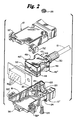
- Figure 2 shows a similar connector in an exploded presentation to illustrate the manner of use of the present invention.
- Such connector plugs serve the purpose of mating a transmission line cable 12, typically, comprising multiple data conductors, for transmitting data from one component of a computer to another.
- a connector might function to mate one end of the transmission line cable 12 to a central processing unit (CPU) (not shown).
- CPU central processing unit
- the other end of the transmission line cable 12 could also be provided with a similar D subminiature connector. That end of the cable 12 could be connected to, for example, a printer (not shown).
- a shell defining the connector plug 10 comprises two portions 10′, 10 ⁇ .
- Each portion 10′, 10 ⁇ is a half of the plug 10 lying on one of opposite sides of a plane of bifurcation.
- the plane of bifurcation extends generally axially with respect to the axis of the overall connector plug. It can be seen, with reference to Figure 2, that the transmission line 12 can be brought into the plug 10, therefore, by separating the shell halves 10′, 10 ⁇ .
- the cable 12 comprises a plurality of conductors such as transmission wires, shielding, etc., each of the conductors going to a different one of the male pins 16 of the connector 10 and shields connected to shell ground.
- Such wires can be mated to their corresponding pins 16, for example, by soldering or other appropriate processes.
- the shell of the connector plug 10 comprises two portions 10′, 10 ⁇ .
- an interior wall 18 of the lower shell half 10 ⁇ is provided with contours in view of the nature of the plug 10.
- a pair of opposed lands 20 extend inwardly into the cavity 22 defined within the shell 10, from the sides thereof. These lands 20 are provided to define apertures 24 through which bolts 26 to secure the two shell halves 10′, 10 ⁇ together can be disposed.
- Figure 2 shows an upper shell portion 10′ which is substantially a mirror image of the lower shell portion half 10 ⁇ .
- the upper portion 10′ therefore, has corresponding lands, each of the lands corresponding to a related land 20 in the lower shell portion 10 ⁇ .
- apertures 24 in the related lands 20 will be in registration so that a bolt 26 can pass completely there through and a nut 28 be threadedly secured onto the shank portion of the two bolts 26.
- each shell portion 10′, 10 ⁇ is provided with a pair of appendages 32 which relate to corresponding appendages on the opposite shell portion.
- An axially extending hole 34 is defined in the connector 10 when the shell portions 10′, 10 ⁇ are mated together. These holes 34 function to receive securing screws or bolts (not shown) which allow secure retention of the connector plug 10 to the electronic equipment with which it is used.
- FIGS 1, 2, and 6 also illustrate a latch 36.
- a latch 36 serves to maintain retention of the pin housing to the connector housing.
- Figure 1a illustrates a manner in which upper and lower shell portions 10′, 10 ⁇ of the connector plug 10 can be fitted with respect to one another.
- the upper portion 10′ is shown as having an outer flange tab 38 which is received in a recess 40 in the lower shell portion 10 ⁇ of the shell 10.
- the present invention as shown in Figure 2, comprises a split ferrite core 42 which is receivable within the connector plug body 10.
- An outer surface 44 of the core 42 as seen in Figure 2, is configured to substantially conform to the inner wall 15 defining a cavity 22 within the plug 10.
- the inner wall 15 is irregular in accommodating the lands 20 for mating, etc.
- the core 42 shown in Figure 2 is produced to have side indentations 46 which conform to these lands 20.
- the core 42 can be bifurcated along a central, generally axially-extending plane (as at 48). This plane, it is intended, is substantially parallel to the plane of bifurcation of the connector plug shell 10.
- production would be such so that, when the two core portions 42′, 42 ⁇ are mated together, they would, aggregatedly define an outer surface 44 conforming substantially to the inner wall 15 of the connector plug 10, and inwardly the core halves would mate perfectly.
- Figure 2 illustrates a sleeve 50 which would, typically, be elastomeric in nature.
- the sleeve 50 can be fitted about the transmission line cable 12 at a location therealong whereby the sleeve 50 would surround the cable 12 at a location along its length which passes through a central aperture 52 in the core 42.
- the bundle of conductors is, thereby, protected against pinching, sharp bending, etc.
- FIG. 6 shows a clip 54 which can be employed to provide cable strain relief and shield grounding.
- the clip 54 is shown as having a central bowed portion 56 which would pass over the bundle of conductors and shield and thus secure them to the wall 15 of the shell portion defining, in part, the cavity 22 in which the core 42 is received.
- the central bowed portion 56 of the clip 54 can be registered with a cradle recess 58 molded into the lower shell half 10 ⁇ to accommodate passage of the bundle of conductors.
- Additional lands 60 having internally threaded apertures 62, can be provided in order to enable the clip 54 to be secured to the shell half 10 ⁇ .
- Appropriate screws 64 are passed through the apertures 66 in the clip 54 and into the internally threaded apertures in these lands 60.
- the connector plug 10 In inserting the core 42, the connector plug 10 would be opened by removing the appropriate bolts 26 or other securing means so that the shell halves 10′, 10 ⁇ could be unmated. With the plug 10 opened in this manner, a first portion 42 ⁇ of the ferrite core 42 would be inserted into the appropriate location within the lower connector plug half 10 ⁇ . This could be done by maneuvering the core half 42 ⁇ until it were easily fitted into position.
- the bundle of conductors would then be fed, along with the protective sleeve 50, into a position wherein the bundle were cradled in the lower half of the central aperture 52 in the core 42.
- the bundle it will be understood, will extend axially through the cradle recess 58 that registers with the central, bowed portion 56 of the clip 54.
- the clip 54 can then be secured into place.
- the upper half of the core 42′ would be fitted over its corresponding lower half 42 ⁇ .
- the upper portion 10′ of the connector plug shell 10 would be closed over the lower portion 10 ⁇ and secured in place by the bolts 26 and their associated nuts 28.
- the core 42 is formed from ferrite, a compound formed from a strong base and ferric oxide which exists in alkaline solution. It has been found that this particular compound is proficient in attenuating radio frequency noise first conducted and then radiated outwardly from a transmission line or cable.
- a series inductor is created in each conductor passing through the core 42. Additionally, a small bypass capacitor is created from each conductor to ground. The formation of the small capacitors is unique with the present invention.
- the data conductors function as first plates of other capacitors.
- the ferrite having a dielectric constant of between 15 and 500,000 forms an excellent dielectric.
- Filtering of each data line is to a lesser degree than is filtering of the shield. This is because each data line has a much smaller area than does the shield. A large amount of filtering on the cable shield and only small amounts on each data line, however, is a situation which is sought to be achieved. As a result, wave shape integrity is maintained.
Landscapes
- Engineering & Computer Science (AREA)
- Computer Networks & Wireless Communication (AREA)
- Signal Processing (AREA)
- Details Of Connecting Devices For Male And Female Coupling (AREA)
- Shielding Devices Or Components To Electric Or Magnetic Fields (AREA)
- Noise Elimination (AREA)
Applications Claiming Priority (4)
| Application Number | Priority Date | Filing Date | Title |
|---|---|---|---|
| US37266189A | 1989-06-28 | 1989-06-28 | |
| US372661 | 1989-06-28 | ||
| US07/419,100 US4992060A (en) | 1989-06-28 | 1989-10-10 | Apparataus and method for reducing radio frequency noise |
| US419100 | 1995-04-10 |
Publications (2)
| Publication Number | Publication Date |
|---|---|
| EP0406118A2 true EP0406118A2 (de) | 1991-01-02 |
| EP0406118A3 EP0406118A3 (en) | 1993-06-09 |
Family
ID=27005851
Family Applications (1)
| Application Number | Title | Priority Date | Filing Date |
|---|---|---|---|
| EP19900401874 Withdrawn EP0406118A3 (en) | 1989-06-28 | 1990-06-28 | Apparatus and method for reducing radio frequency noise |
Country Status (5)
| Country | Link |
|---|---|
| US (1) | US4992060A (de) |
| EP (1) | EP0406118A3 (de) |
| JP (1) | JPH0337981A (de) |
| KR (1) | KR940003482B1 (de) |
| CA (1) | CA2020000A1 (de) |
Cited By (2)
| Publication number | Priority date | Publication date | Assignee | Title |
|---|---|---|---|---|
| EP0684665A3 (de) * | 1994-05-25 | 1996-08-28 | Molex Inc | Abgeschirmte Steckereinheit. |
| GB2329531A (en) * | 1997-06-27 | 1999-03-24 | Omega Engineering | Connector with protection from electromagnetic emissions |
Families Citing this family (81)
| Publication number | Priority date | Publication date | Assignee | Title |
|---|---|---|---|---|
| JPH0479507A (ja) * | 1990-07-20 | 1992-03-12 | Amp Japan Ltd | フィルタ及びフィルタ付電気コネクタ |
| US5257950A (en) * | 1991-07-17 | 1993-11-02 | The Whitaker Corporation | Filtered electrical connector |
| DE4237914C2 (de) * | 1992-11-10 | 1996-10-02 | Elco Europ Gmbh | Steckverbinder |
| US5500629A (en) * | 1993-09-10 | 1996-03-19 | Meyer Dennis R | Noise suppressor |
| US5456619A (en) * | 1994-08-31 | 1995-10-10 | Berg Technology, Inc. | Filtered modular jack assembly and method of use |
| US5629842A (en) * | 1995-04-05 | 1997-05-13 | Zero Emissions Technology Inc. | Two-stage, high voltage inductor |
| JP3571410B2 (ja) * | 1995-04-27 | 2004-09-29 | 本田技研工業株式会社 | 自動車用多重通信システムの配線構造 |
| US5934934A (en) * | 1997-04-22 | 1999-08-10 | Communication Systems, Inc. | Shielded couplers |
| US5982253A (en) * | 1997-08-27 | 1999-11-09 | Nartron Corporation | In-line module for attenuating electrical noise with male and female blade terminals |
| US6078117A (en) * | 1997-08-27 | 2000-06-20 | Nartron Corporation | End cap assembly and electrical motor utilizing same |
| US6054781A (en) * | 1998-07-24 | 2000-04-25 | Lucent Technologies, Inc. | Voltage bus filtering scheme for a battery power plant |
| US6276943B1 (en) | 1999-02-22 | 2001-08-21 | Amphenol Corporation | Modular plug connector and improved receptacle therefore |
| US6538524B1 (en) * | 2000-03-29 | 2003-03-25 | Hewlett-Packard Company | Using electrically lossy transmission systems to reduce computer RF emissions |
| KR200215666Y1 (ko) * | 2000-09-08 | 2001-03-15 | 혜성전자공업주식회사 | 페라이트 코아가 내장된 디서브 콘넥타 |
| US6354879B1 (en) | 2000-10-05 | 2002-03-12 | Ball Aerospace & Technologies Corp. | Connector for shielded conductors |
| JP4194019B2 (ja) * | 2002-06-28 | 2008-12-10 | Fdk株式会社 | コネクタ付き信号伝送ケーブル |
| US6867362B2 (en) * | 2003-03-07 | 2005-03-15 | Hewlett-Packard Development Company, L.P. | Cable extension for reducing EMI emissions |
| US20090291593A1 (en) | 2005-06-30 | 2009-11-26 | Prescott Atkinson | High frequency broadside-coupled electrical connector |
| CN101101806A (zh) * | 2006-07-07 | 2008-01-09 | 富士康(昆山)电脑接插件有限公司 | 线缆 |
| US8425254B2 (en) * | 2007-03-19 | 2013-04-23 | Fci Automotive Holding | Electrical connector with ferrite block assembly |
| ATE543237T1 (de) * | 2007-06-15 | 2012-02-15 | Souriau | Subminiatur abgeschirmte verbinderanordnung und verfahren zum austatten einer solchen verbinderandordnug. |
| US9124009B2 (en) * | 2008-09-29 | 2015-09-01 | Amphenol Corporation | Ground sleeve having improved impedance control and high frequency performance |
| US8546688B2 (en) * | 2009-04-14 | 2013-10-01 | John Martin Horan | High speed data cable with shield connection |
| CN102714363B (zh) | 2009-11-13 | 2015-11-25 | 安费诺有限公司 | 高性能小形状因数的连接器 |
| WO2011106572A2 (en) | 2010-02-24 | 2011-09-01 | Amphenol Corporation | High bandwidth connector |
| US8243470B2 (en) * | 2010-03-31 | 2012-08-14 | International Business Machines Corporation | Ferrite inductors integrated within top-mounted input/output cable port assembly of an electronics rack |
| US8243469B2 (en) * | 2010-03-31 | 2012-08-14 | International Business Machines Corporation | Ferrite inductors integrated within input/output cable port assembly of an electronics rack |
| WO2011140438A2 (en) | 2010-05-07 | 2011-11-10 | Amphenol Corporation | High performance cable connector |
| US8657627B2 (en) | 2011-02-02 | 2014-02-25 | Amphenol Corporation | Mezzanine connector |
| WO2013059317A1 (en) | 2011-10-17 | 2013-04-25 | Amphenol Corporation | Electrical connector with hybrid shield |
| JP2013165205A (ja) * | 2012-02-13 | 2013-08-22 | Sharp Corp | ワイヤハーネス及びそのワイヤハーネスを用いた電子機器、並びに、フェライトコアの固定方法 |
| CN104604045B (zh) | 2012-06-29 | 2018-04-10 | 安费诺有限公司 | 低成本高性能的射频连接器 |
| CN104704682B (zh) | 2012-08-22 | 2017-03-22 | 安费诺有限公司 | 高频电连接器 |
| CN105191003B (zh) | 2013-03-13 | 2017-12-08 | 安费诺有限公司 | 用于高速电连接器的壳体 |
| US9484674B2 (en) | 2013-03-14 | 2016-11-01 | Amphenol Corporation | Differential electrical connector with improved skew control |
| US9609765B2 (en) * | 2013-09-27 | 2017-03-28 | Intel Corporation | Chassis of electronic device |
| WO2015112717A1 (en) | 2014-01-22 | 2015-07-30 | Amphenol Corporation | High speed, high density electrical connector with shielded signal paths |
| CN111641084B (zh) | 2014-11-12 | 2022-05-24 | 安费诺有限公司 | 在配合区域中具有阻抗控制的非常高速、高密度电互连系统 |
| US10541482B2 (en) | 2015-07-07 | 2020-01-21 | Amphenol Fci Asia Pte. Ltd. | Electrical connector with cavity between terminals |
| TWI793945B (zh) | 2015-07-23 | 2023-02-21 | 美商安芬諾Tcs公司 | 連接器、製造連接器方法、用於連接器的擴充器模組以及電子系統 |
| TWI790785B (zh) | 2016-05-31 | 2023-01-21 | 美商安芬諾股份有限公司 | 電終端、纜線總成以及纜線端接方法 |
| CN109155491B (zh) | 2016-06-01 | 2020-10-23 | 安费诺Fci连接器新加坡私人有限公司 | 高速电连接器 |
| TWI790798B (zh) | 2016-08-23 | 2023-01-21 | 美商安芬諾股份有限公司 | 可配置為高性能的連接器 |
| US10205286B2 (en) | 2016-10-19 | 2019-02-12 | Amphenol Corporation | Compliant shield for very high speed, high density electrical interconnection |
| US10944214B2 (en) | 2017-08-03 | 2021-03-09 | Amphenol Corporation | Cable connector for high speed interconnects |
| CN118630506A (zh) | 2017-10-30 | 2024-09-10 | 安费诺富加宜(亚洲)私人有限公司 | 低串扰卡缘连接器 |
| US10601181B2 (en) | 2017-12-01 | 2020-03-24 | Amphenol East Asia Ltd. | Compact electrical connector |
| US10777921B2 (en) | 2017-12-06 | 2020-09-15 | Amphenol East Asia Ltd. | High speed card edge connector |
| US10665973B2 (en) | 2018-03-22 | 2020-05-26 | Amphenol Corporation | High density electrical connector |
| CN112514175B (zh) | 2018-04-02 | 2022-09-09 | 安达概念股份有限公司 | 受控阻抗顺应性线缆终端头 |
| CN208862209U (zh) | 2018-09-26 | 2019-05-14 | 安费诺东亚电子科技(深圳)有限公司 | 一种连接器及其应用的pcb板 |
| WO2020073460A1 (en) | 2018-10-09 | 2020-04-16 | Amphenol Commercial Products (Chengdu) Co. Ltd. | High-density edge connector |
| TWM576774U (zh) | 2018-11-15 | 2019-04-11 | 香港商安費諾(東亞)有限公司 | 具有防位移結構之金屬殼體及其連接器 |
| US10931062B2 (en) | 2018-11-21 | 2021-02-23 | Amphenol Corporation | High-frequency electrical connector |
| US11381015B2 (en) | 2018-12-21 | 2022-07-05 | Amphenol East Asia Ltd. | Robust, miniaturized card edge connector |
| WO2020154526A1 (en) | 2019-01-25 | 2020-07-30 | Fci Usa Llc | I/o connector configured for cabled connection to the midboard |
| CN116247455A (zh) | 2019-01-25 | 2023-06-09 | 富加宜(美国)有限责任公司 | 电连接器 |
| US11189971B2 (en) | 2019-02-14 | 2021-11-30 | Amphenol East Asia Ltd. | Robust, high-frequency electrical connector |
| TW202439723A (zh) | 2019-02-19 | 2024-10-01 | 美商安芬諾股份有限公司 | 電連接器及用於製造電連接器之方法 |
| CN113728521B (zh) | 2019-02-22 | 2025-03-18 | 安费诺有限公司 | 高性能线缆连接器组件 |
| TWM582251U (zh) | 2019-04-22 | 2019-08-11 | 香港商安費諾(東亞)有限公司 | Connector set with built-in locking mechanism and socket connector thereof |
| TW202448032A (zh) | 2019-05-20 | 2024-12-01 | 美商安芬諾股份有限公司 | 連接器模組、連接器、電子組件、電連接器以及連接器模組的薄片 |
| TWI888408B (zh) | 2019-09-19 | 2025-07-01 | 美商安芬諾股份有限公司 | 電連接器及連接纜線至基板的方法 |
| US11588277B2 (en) | 2019-11-06 | 2023-02-21 | Amphenol East Asia Ltd. | High-frequency electrical connector with lossy member |
| US11799230B2 (en) | 2019-11-06 | 2023-10-24 | Amphenol East Asia Ltd. | High-frequency electrical connector with in interlocking segments |
| TW202607982A (zh) | 2020-01-27 | 2026-02-16 | 美商Fci美國有限責任公司 | 電連接器 |
| TW202534957A (zh) | 2020-01-27 | 2025-09-01 | 美商Fci美國有限責任公司 | 高速及高密度之直接耦合垂直式連接器 |
| CN113258325A (zh) | 2020-01-28 | 2021-08-13 | 富加宜(美国)有限责任公司 | 高频中板连接器 |
| US11637391B2 (en) | 2020-03-13 | 2023-04-25 | Amphenol Commercial Products (Chengdu) Co., Ltd. | Card edge connector with strength member, and circuit board assembly |
| US11728585B2 (en) | 2020-06-17 | 2023-08-15 | Amphenol East Asia Ltd. | Compact electrical connector with shell bounding spaces for receiving mating protrusions |
| US11831092B2 (en) | 2020-07-28 | 2023-11-28 | Amphenol East Asia Ltd. | Compact electrical connector |
| US11652307B2 (en) | 2020-08-20 | 2023-05-16 | Amphenol East Asia Electronic Technology (Shenzhen) Co., Ltd. | High speed connector |
| CN212874843U (zh) | 2020-08-31 | 2021-04-02 | 安费诺商用电子产品(成都)有限公司 | 电连接器 |
| CN215816516U (zh) | 2020-09-22 | 2022-02-11 | 安费诺商用电子产品(成都)有限公司 | 电连接器 |
| CN213636403U (zh) | 2020-09-25 | 2021-07-06 | 安费诺商用电子产品(成都)有限公司 | 电连接器 |
| US11569613B2 (en) | 2021-04-19 | 2023-01-31 | Amphenol East Asia Ltd. | Electrical connector having symmetrical docking holes |
| US12176650B2 (en) | 2021-05-05 | 2024-12-24 | Amphenol East Asia Limited (Hong Kong) | Electrical connector with guiding structure and mating groove and method of connecting electrical connector |
| CN215266741U (zh) | 2021-08-13 | 2021-12-21 | 安费诺商用电子产品(成都)有限公司 | 一种满足高带宽传输的高性能卡类连接器 |
| USD1002553S1 (en) | 2021-11-03 | 2023-10-24 | Amphenol Corporation | Gasket for connector |
| USD1068685S1 (en) | 2021-12-14 | 2025-04-01 | Amphenol Corporation | Electrical connector |
| USD1067191S1 (en) | 2021-12-14 | 2025-03-18 | Amphenol Corporation | Electrical connector |
Family Cites Families (17)
| Publication number | Priority date | Publication date | Assignee | Title |
|---|---|---|---|---|
| US2594890A (en) * | 1950-08-16 | 1952-04-29 | Bell Telephone Labor Inc | Contact protection arrangement |
| US2865006A (en) * | 1954-02-15 | 1958-12-16 | Sabaroff Samuel | Longitudinal isolation device for high frequency signal transmission lines |
| US3134950A (en) * | 1961-03-24 | 1964-05-26 | Gen Electric | Radio frequency attenuator |
| US3289118A (en) * | 1962-03-29 | 1966-11-29 | Globe Union Inc | Filter |
| US3538464A (en) * | 1963-08-20 | 1970-11-03 | Erie Technological Prod Inc | Multiple pin connector having ferrite core stacked capacitor filter |
| US3243738A (en) * | 1963-11-19 | 1966-03-29 | Allen Bradley Co | Feed-through capacitor |
| USRE29258E (en) * | 1969-12-09 | 1977-06-07 | Amp Incorporated | Coated ferrite RF filters |
| US3789263A (en) * | 1972-02-04 | 1974-01-29 | Amp Inc | Rf filters with glass on a substrate |
| US3930210A (en) * | 1973-12-12 | 1975-12-30 | Amp Inc | Mounted ceramic filter |
| DE2441669C3 (de) * | 1974-08-30 | 1978-05-03 | Siemens Ag, 1000 Berlin Und 8000 Muenchen | Anordnung zur Schirmung eines mehrpoligen Leitungssteckers |
| JPS5984414A (ja) * | 1982-11-04 | 1984-05-16 | 株式会社村田製作所 | Lcフイルタ |
| US4506234A (en) * | 1983-06-17 | 1985-03-19 | The United States Of America As Represented By The Secretary Of The Navy | Amplitude and phase modulation in fin-lines by electrical tuning |
| JPS60121277U (ja) * | 1984-01-23 | 1985-08-15 | ヒロセ電機株式会社 | カバ−ケ−スを有する電気コネクタ |
| US4691208A (en) * | 1984-07-02 | 1987-09-01 | The United States Of America As Represented By The Secretary Of The Army | Ferrite waveguide scanning antenna |
| US4679013A (en) * | 1985-12-20 | 1987-07-07 | Amp Incorporated | Filtered electrical connector |
| JPS6389680U (de) * | 1986-11-29 | 1988-06-10 | ||
| JPS6452388A (en) * | 1987-08-24 | 1989-02-28 | Hirose Electric Co Ltd | Electromagnetic interference countermeasure electric connector |
-
1989
- 1989-10-10 US US07/419,100 patent/US4992060A/en not_active Expired - Fee Related
-
1990
- 1990-06-27 CA CA002020000A patent/CA2020000A1/en not_active Abandoned
- 1990-06-28 EP EP19900401874 patent/EP0406118A3/en not_active Withdrawn
- 1990-06-28 JP JP2168606A patent/JPH0337981A/ja active Pending
- 1990-06-28 KR KR1019900009668A patent/KR940003482B1/ko not_active Expired - Fee Related
Cited By (3)
| Publication number | Priority date | Publication date | Assignee | Title |
|---|---|---|---|---|
| EP0684665A3 (de) * | 1994-05-25 | 1996-08-28 | Molex Inc | Abgeschirmte Steckereinheit. |
| GB2329531A (en) * | 1997-06-27 | 1999-03-24 | Omega Engineering | Connector with protection from electromagnetic emissions |
| GB2329531B (en) * | 1997-06-27 | 2002-03-13 | Omega Engineering | Connector with protection from radiated and conducted electromagnetic emissions |
Also Published As
| Publication number | Publication date |
|---|---|
| JPH0337981A (ja) | 1991-02-19 |
| KR940003482B1 (ko) | 1994-04-22 |
| KR910002052A (ko) | 1991-01-31 |
| CA2020000A1 (en) | 1990-12-28 |
| US4992060A (en) | 1991-02-12 |
| EP0406118A3 (en) | 1993-06-09 |
Similar Documents
| Publication | Publication Date | Title |
|---|---|---|
| US4992060A (en) | Apparataus and method for reducing radio frequency noise | |
| US5769661A (en) | In-service removable cable ground connection | |
| US10396508B2 (en) | Coaxial cable connector with integral RFI protection | |
| JP2978950B2 (ja) | シールドコネクタ | |
| TWI602371B (zh) | 具有集成rfi保護的同軸電纜連接器 | |
| US10290958B2 (en) | Coaxial cable connector with integral RFI protection and biasing ring | |
| US9287659B2 (en) | Coaxial cable connector with integral RFI protection | |
| US5012042A (en) | Cable entry device for EMI shielded cabinets | |
| KR970004152B1 (ko) | 전기 접속기용 케이블 차폐 종단 장치 | |
| US9793692B1 (en) | Grounded cable assembly of a communication system | |
| US9991651B2 (en) | Coaxial cable connector with post including radially expanding tabs | |
| US4579415A (en) | Grounding of shielded cables in a plug and receptacle electrical connector | |
| US6887105B2 (en) | Providing shields to reduce electromagnetic interference from connectors | |
| US5713748A (en) | Cable grounding and strain relief apparatus | |
| US4906199A (en) | Shield grounding connector and method | |
| US4381129A (en) | Grounded, multi-pin connector for shielded flat cable | |
| US4422700A (en) | Grounded multi-pin connector for shielded flat cable | |
| US6612870B1 (en) | Connector of the input/output type with grounded shielded cables and method of producing and of mounting such a connector | |
| US4399318A (en) | EMI Shielding enclosure for a cable connector | |
| JPH05217635A (ja) | シールド強化形同軸コネクタ | |
| US20030034165A1 (en) | Method and apparatus for external grounding of plastic backshell connectors | |
| JPH07240245A (ja) | 同軸線接続機器と同軸ケーブルの接続方法 | |
| JPH02184216A (ja) | ケーブルシールド終端装置 | |
| Santamaria et al. | A comparison of unshielded wire to shielded wire with shields terminated using pigtails | |
| MXPA99006691A (en) | In-service removable cable ground connection |
Legal Events
| Date | Code | Title | Description |
|---|---|---|---|
| PUAI | Public reference made under article 153(3) epc to a published international application that has entered the european phase |
Free format text: ORIGINAL CODE: 0009012 |
|
| AK | Designated contracting states |
Kind code of ref document: A2 Designated state(s): DE FR GB |
|
| PUAL | Search report despatched |
Free format text: ORIGINAL CODE: 0009013 |
|
| AK | Designated contracting states |
Kind code of ref document: A3 Designated state(s): DE FR GB |
|
| STAA | Information on the status of an ep patent application or granted ep patent |
Free format text: STATUS: THE APPLICATION IS DEEMED TO BE WITHDRAWN |
|
| 18D | Application deemed to be withdrawn |
Effective date: 19940110 |