EP0406144B1 - Garniture d'étanchéité à talon annulaire d'ancrage - Google Patents
Garniture d'étanchéité à talon annulaire d'ancrage Download PDFInfo
- Publication number
- EP0406144B1 EP0406144B1 EP90470039A EP90470039A EP0406144B1 EP 0406144 B1 EP0406144 B1 EP 0406144B1 EP 90470039 A EP90470039 A EP 90470039A EP 90470039 A EP90470039 A EP 90470039A EP 0406144 B1 EP0406144 B1 EP 0406144B1
- Authority
- EP
- European Patent Office
- Prior art keywords
- anchoring
- heel
- seal
- gasket
- lining
- Prior art date
- Legal status (The legal status is an assumption and is not a legal conclusion. Google has not performed a legal analysis and makes no representation as to the accuracy of the status listed.)
- Expired - Lifetime
Links
- 239000011324 bead Substances 0.000 title 1
- 238000004873 anchoring Methods 0.000 claims abstract description 37
- 238000007789 sealing Methods 0.000 claims abstract description 30
- 230000004323 axial length Effects 0.000 claims description 8
- 230000006835 compression Effects 0.000 claims description 6
- 238000007906 compression Methods 0.000 claims description 6
- 229920001971 elastomer Polymers 0.000 claims description 4
- 239000000806 elastomer Substances 0.000 claims description 4
- 230000002093 peripheral effect Effects 0.000 abstract 1
- 239000002184 metal Substances 0.000 description 2
- 238000012856 packing Methods 0.000 description 2
- 230000035882 stress Effects 0.000 description 2
- 206010063493 Premature ageing Diseases 0.000 description 1
- 208000032038 Premature aging Diseases 0.000 description 1
- 239000012141 concentrate Substances 0.000 description 1
- 230000000694 effects Effects 0.000 description 1
- 239000012530 fluid Substances 0.000 description 1
- 238000009434 installation Methods 0.000 description 1
- 238000000926 separation method Methods 0.000 description 1
Images


Classifications
-
- F—MECHANICAL ENGINEERING; LIGHTING; HEATING; WEAPONS; BLASTING
- F16—ENGINEERING ELEMENTS AND UNITS; GENERAL MEASURES FOR PRODUCING AND MAINTAINING EFFECTIVE FUNCTIONING OF MACHINES OR INSTALLATIONS; THERMAL INSULATION IN GENERAL
- F16L—PIPES; JOINTS OR FITTINGS FOR PIPES; SUPPORTS FOR PIPES, CABLES OR PROTECTIVE TUBING; MEANS FOR THERMAL INSULATION IN GENERAL
- F16L21/00—Joints with sleeve or socket
- F16L21/02—Joints with sleeve or socket with elastic sealing rings between pipe and sleeve or between pipe and socket, e.g. with rolling or other prefabricated profiled rings
- F16L21/03—Joints with sleeve or socket with elastic sealing rings between pipe and sleeve or between pipe and socket, e.g. with rolling or other prefabricated profiled rings placed in the socket before connection
-
- F—MECHANICAL ENGINEERING; LIGHTING; HEATING; WEAPONS; BLASTING
- F16—ENGINEERING ELEMENTS AND UNITS; GENERAL MEASURES FOR PRODUCING AND MAINTAINING EFFECTIVE FUNCTIONING OF MACHINES OR INSTALLATIONS; THERMAL INSULATION IN GENERAL
- F16L—PIPES; JOINTS OR FITTINGS FOR PIPES; SUPPORTS FOR PIPES, CABLES OR PROTECTIVE TUBING; MEANS FOR THERMAL INSULATION IN GENERAL
- F16L37/00—Couplings of the quick-acting type
- F16L37/08—Couplings of the quick-acting type in which the connection between abutting or axially overlapping ends is maintained by locking members
- F16L37/084—Couplings of the quick-acting type in which the connection between abutting or axially overlapping ends is maintained by locking members combined with automatic locking
- F16L37/0845—Couplings of the quick-acting type in which the connection between abutting or axially overlapping ends is maintained by locking members combined with automatic locking by means of retaining members associated with the packing member
-
- Y—GENERAL TAGGING OF NEW TECHNOLOGICAL DEVELOPMENTS; GENERAL TAGGING OF CROSS-SECTIONAL TECHNOLOGIES SPANNING OVER SEVERAL SECTIONS OF THE IPC; TECHNICAL SUBJECTS COVERED BY FORMER USPC CROSS-REFERENCE ART COLLECTIONS [XRACs] AND DIGESTS
- Y10—TECHNICAL SUBJECTS COVERED BY FORMER USPC
- Y10S—TECHNICAL SUBJECTS COVERED BY FORMER USPC CROSS-REFERENCE ART COLLECTIONS [XRACs] AND DIGESTS
- Y10S285/00—Pipe joints or couplings
- Y10S285/91—Gaskets
Definitions
- the present invention relates to an elastomeric seal, intended to be mounted in a pipe socket, this seal comprising an anchoring structure and a sealing body operating by radial compression, the structure anchor having an anchor heel, located at a radially outer face of the seal and forming a radial projection relative thereto.
- document FR 2 554 205 discloses a seal of the type described in the preamble of claim 1.
- the anchoring heel of this lining is extended, in the radial direction internal to the internal surface of the lining, by an annular compression foot.
- the packing is made of a single hardness elastomer.
- the object of the present invention is therefore to provide a seal having a geometry anchoring heel, which allows easy fitting of this seal in a socket in which it is intended to be housed.
- the present invention therefore relates to an elastomeric seal for a joint between two pipes.
- Said gasket is intended to be mounted in a pipe socket, this gasket comprising an anchoring structure and a sealing body operating by radial compression, the anchoring structure consisting of a heel of anchor, located on a radially outer face of the seal and forming a radial projection relative thereto, notches being formed on an external radial surface of the seal in the anchor heel, said notches being hollowed out on the entire axial length of said heel, and the ratio between the height H of the anchoring heel and the thickness E of the sealing body being greater than 0.2.
- a packing 1 of axis XX has an anchoring structure 2 of axial length L2 and a sealing body 3 of axial length L3 extending the structure d anchoring 2 along axis XX, an intermediate connecting structure 4 of axial length L4 connecting the anchoring structure 2 to the sealing body 3.
- the axial length L2 of the anchoring structure 2 represents from 25% to 35% of the total axial length L1 of the lining 1.
- volume of the anchoring structure 2 represents between 25% and 35% of the total volume of the seal 1.
- the seal 1 has a radially external surface consisting of an anchoring heel 5 of the anchoring structure 2, of cylindrical external surface and of diameter D1, connected to a frustoconical surface 6 of the connection structure 4 by a face 7, flat, or slightly frustoconical with a taper converging towards the sealing body 3 and a curved surface 8.
- the frustoconical surface 6 is extended, along the axis X-X, by a cylindrical surface 9 of the sealing body 3.
- the surface 6 has an open taper towards the sealing body 3, the surfaces 6, 7 and 8 forming a concave surface, the surfaces 7 and 8 forming a cheek of equal height H and therefore of internal diameter equal to (D1- 2xH).
- the diameter D2 of the cylindrical surface 9 of the sealing body is less than or equal to D1 and greater than (D1- 2xH).
- the seal 1 has, on its internal surface, an annular base 10, in internal radial extension of the anchoring heel 5, that is to say opposite the latter.
- This annular base 10 is constituted by a cylindrical internal surface 11 of diameter D11 and by a frustoconical entry surface 12 of axis X-X connected to the anchoring heel 5 by a slightly frustoconical surface 13 of axis X-X.
- the sealing body 3 has, on its internal surface located near the annular base 10, a frustoconical surface 14 of half-angle at the apex of about 40 °, with an open taper towards the anchoring structure 2, followed by a second cylindrical internal surface 15 of axis XX of internal diameter D12 terminated by a frustoconical surface 17 of half-angle at the top from 10 ° to 20 °, with conicity open towards the anchoring structure 2.
- the internal diameter D12 of the internal surface 15 is less than the diameter D11 of the surface 11 of the annular base 10.
- the transverse face of the end of the sealing body 3 opposite the face 13 of the anchoring structure 2 has a lobe 16, projecting axially by relative to this transverse face and two faces 25 and 26 constituting a part of said transverse face on either side of lobe 16.
- the surface 26 forms with the surface 17 a small triangular lip 18, the surface 25, flat or slightly frustoconical perpendicular to the axis X-X, connecting to the external cylindrical face 9 of the sealing body 3.
- the edge formed by the surface 11 of the foot 10 and the annular groove 19 is located in line with the surface 7 laterally limiting the anchoring heel 5.
- the ratio between the minimum thickness e of the lining 1, in line with the groove 19 and the curved surface 8, and the height H of the anchoring heel 5 is between 1.3 and 2.5.
- the ratio between the height H of the anchoring heel 5 and the thickness E of the sealing body must be greater than 0.2 so that the anchoring effect provided by the anchoring heel 5, in combination with the annular base 10 remains sufficient.
- the O / W ratio is between 0.25 and 0.38.
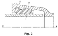
- a seal 1 of the type described above is intended to be mounted inside a socket 30 of axis X-X of a pipe to be connected.
- the anchoring heel 5 is received in a groove 32 of said socket, the surfaces 6, 7, 8 and 9 of the lining 1 coming into contact with corresponding surfaces of the socket 30.
- the seal is folded, for example manually or by a portable or non-portable tool, until it is deformed enough to allow it to be inserted into the socket.
- the seal undergoes a cardioid deformation, that is to say in the form of two lobes separated by an invagination.
- each notch 27 is of a depth which can reach the height H of the heel 5 and preferably greater than 0.66 x H.
- each notch 27 has, in a section plane perpendicular to the axis X-X of the lining, a section in an arc.
- the seal according to the invention is intended to receive metal inserts 33 for locking a male end of a pipe to be connected in a socket fitted with a seal. , another pipe to connect with the previous one.
- This phenomenon is particularly important in the radially external zones of the lining which are tensioned when the latter is folded.
- the use of the notches 27 of the lining according to the present invention if it makes it possible to reduce the stiffness of said lining, also makes it possible to concentrate the stresses at the level of these notches thus considerably reducing these stresses, and particularly the tension , at the contact surfaces between the locking inserts 33 and the elastomer constituting the lining which surrounds them.
- the present invention therefore makes it possible to produce a gasket with an anchor heel and a sealing body operating by radial compression which has a lesser stiffness than in the prior art while ensuring perfect sealing.
Landscapes
- General Engineering & Computer Science (AREA)
- Engineering & Computer Science (AREA)
- Mechanical Engineering (AREA)
- Gasket Seals (AREA)
- Joints With Sleeves (AREA)
- Footwear And Its Accessory, Manufacturing Method And Apparatuses (AREA)
- Road Signs Or Road Markings (AREA)
- Protection Of Pipes Against Damage, Friction, And Corrosion (AREA)
- Sealing Devices (AREA)
- Hybrid Cells (AREA)
- Flanged Joints, Insulating Joints, And Other Joints (AREA)
- Prostheses (AREA)
- Joining Of Building Structures In Genera (AREA)
- Seal Device For Vehicle (AREA)
- Sealing Battery Cases Or Jackets (AREA)
- Materials For Medical Uses (AREA)
- Sealing Material Composition (AREA)
- Processes Of Treating Macromolecular Substances (AREA)
Applications Claiming Priority (2)
| Application Number | Priority Date | Filing Date | Title |
|---|---|---|---|
| FR8908858A FR2649177B1 (fr) | 1989-06-28 | 1989-06-28 | Garniture d'etancheite a talon annulaire d'ancrage |
| FR8908858 | 1989-06-28 |
Publications (2)
| Publication Number | Publication Date |
|---|---|
| EP0406144A1 EP0406144A1 (fr) | 1991-01-02 |
| EP0406144B1 true EP0406144B1 (fr) | 1994-01-26 |
Family
ID=9383372
Family Applications (1)
| Application Number | Title | Priority Date | Filing Date |
|---|---|---|---|
| EP90470039A Expired - Lifetime EP0406144B1 (fr) | 1989-06-28 | 1990-06-25 | Garniture d'étanchéité à talon annulaire d'ancrage |
Country Status (22)
| Country | Link |
|---|---|
| US (1) | US5058907A (ko) |
| EP (1) | EP0406144B1 (ko) |
| JP (1) | JPH0379866A (ko) |
| KR (1) | KR970009017B1 (ko) |
| CN (1) | CN1024215C (ko) |
| AT (1) | ATE100916T1 (ko) |
| AU (1) | AU640146B2 (ko) |
| BR (1) | BR9003025A (ko) |
| CA (1) | CA2019406C (ko) |
| DD (1) | DD296147A5 (ko) |
| DE (1) | DE69006273T2 (ko) |
| DK (1) | DK0406144T3 (ko) |
| EG (1) | EG18975A (ko) |
| ES (1) | ES2041637T3 (ko) |
| FR (1) | FR2649177B1 (ko) |
| MA (1) | MA21965A1 (ko) |
| OA (1) | OA09181A (ko) |
| PT (1) | PT8389U (ko) |
| RU (1) | RU2013681C1 (ko) |
| TN (1) | TNSN90095A1 (ko) |
| TR (1) | TR25092A (ko) |
| ZA (1) | ZA904434B (ko) |
Families Citing this family (43)
| Publication number | Priority date | Publication date | Assignee | Title |
|---|---|---|---|---|
| SE9100583L (sv) * | 1991-03-01 | 1992-09-02 | Forsheda Ab | Roerfog |
| JP3356468B2 (ja) * | 1992-10-09 | 2002-12-16 | 株式会社前川製作所 | スクリューロータ |
| JP2576785Y2 (ja) * | 1993-02-22 | 1998-07-16 | 矢崎総業株式会社 | 防水コネクタの嵌合構造 |
| GB9417284D0 (en) * | 1994-08-26 | 1994-10-19 | Hepworth Building Prod | Push-fit pipe couplings |
| US6629708B2 (en) * | 1997-04-15 | 2003-10-07 | Swagelok Company | Ferrule with relief to reduce galling |
| US6126173A (en) * | 1998-01-27 | 2000-10-03 | Poly-Tec Products, Inc. | Extruded gasket for cored manholes |
| US5983820A (en) * | 1998-11-03 | 1999-11-16 | Attwood Corporation | Retractable cleat |
| USD458891S1 (en) | 1998-11-03 | 2002-06-18 | Steelcase Development Corporation | Lift-up cleat |
| US6299176B1 (en) * | 1999-03-03 | 2001-10-09 | S&B Technical Products | Dual purpose low insertion force gasket |
| US6422569B1 (en) | 1999-11-30 | 2002-07-23 | Parker-Hannifin Corporation | Snap-in retainer for a fluid seal |
| US6367802B1 (en) | 1999-11-30 | 2002-04-09 | Malcolm Mann Inc. | Annular gasket with locking structure |
| US6336640B1 (en) | 2000-06-02 | 2002-01-08 | Malcolm Mann Inc. | Gasket |
| US7108289B1 (en) * | 2000-06-08 | 2006-09-19 | United States Pipe And Foundry Company, Llc | Restraining gasket for mechanical joints of pipes |
| US7104573B2 (en) * | 2000-06-08 | 2006-09-12 | United States Pipe And Foundy Company, Llc | Energized restraining gasket for mechanical joints of pipes |
| US7469905B2 (en) * | 2000-11-30 | 2008-12-30 | Springseal Inc. | Permanently lubricated film gasket and method of manufacture |
| US6550775B2 (en) | 2000-11-30 | 2003-04-22 | Malcolm Mann, Inc. | Annular gasket |
| US20040041347A1 (en) * | 2000-11-30 | 2004-03-04 | Beach Jefferey Kurtis | Permanently lubricated gasket |
| US6688652B2 (en) * | 2001-12-12 | 2004-02-10 | U.S. Pipe And Foundry Company | Locking device and method for securing telescoped pipe |
| JP4252785B2 (ja) * | 2002-10-01 | 2009-04-08 | 株式会社パイオラックス | 配管用コネクタ及びその製造方法 |
| US7140617B2 (en) * | 2003-05-30 | 2006-11-28 | Dana Corporation | Sealing ring for an intake manifold |
| US7137653B2 (en) * | 2003-09-25 | 2006-11-21 | United States Pipe And Foundry Company, Llc | Centroidally twistable compression ring for pipe joints |
| US7410174B2 (en) * | 2004-03-04 | 2008-08-12 | S & B Technical Products, Inc. | Restraining mechanical joint gasket for ductile iron pipe |
| US7207606B2 (en) * | 2004-04-19 | 2007-04-24 | United States Pipe And Foundry Company, Llc | Mechanical pipe joint, gasket, and method for restraining pipe spigots in mechanical pipe joint bell sockets |
| DE202004007290U1 (de) * | 2004-05-07 | 2005-09-15 | Viega Gmbh & Co Kg | Dichtelement |
| US7766341B2 (en) * | 2004-07-16 | 2010-08-03 | Ckd Corporation | Seal structure, fluid device, integrated valve, and sealing member |
| US7731884B2 (en) * | 2004-12-08 | 2010-06-08 | Advanced Elastomer Systems, L.P. | Molded gasket and method of making |
| DE102005038397B4 (de) * | 2005-08-12 | 2007-07-12 | A. Raymond Et Cie | Kupplung für eine Fluidleitungsanordnung |
| ITBO20060101A1 (it) * | 2006-02-13 | 2007-08-14 | Sica Spa | Condotto in materiale termoplastico, in particolare in materiale poliolefinico per fluidi in pressione, con estremita' sagomata a bicchiere. |
| US8474830B2 (en) | 2007-06-07 | 2013-07-02 | Springseal, Inc. | Gasket |
| CA2705351C (en) * | 2007-10-03 | 2014-01-21 | Anvil International, Lp | Coupling gaskets and associated methods |
| CA2726090C (en) * | 2008-05-27 | 2017-11-28 | Springseal, Inc. | Pipe coupling assembly |
| CN103148293B (zh) * | 2009-01-27 | 2015-07-29 | 株式会社久保田 | 管接头 |
| DE102010022205B4 (de) * | 2010-05-20 | 2022-01-27 | Drägerwerk AG & Co. KGaA | Verbindungselement für Komponenten in einem Atemsystem |
| US8490273B1 (en) * | 2010-10-08 | 2013-07-23 | Mcwane Global | Pipe joint gasket and method of using same |
| US8801049B2 (en) | 2011-04-29 | 2014-08-12 | Springseal, Inc. | Pipe coupling system and method |
| MY176920A (en) * | 2012-06-25 | 2020-08-26 | Kubota Kk | Sealing material, pressing ring, joint, and valve |
| DE102012021683A1 (de) * | 2012-11-03 | 2014-05-08 | Festo Ag & Co. Kg | Anschlussvorrichtung für mindestens eine Fluiddleitung |
| US9109701B1 (en) * | 2013-10-17 | 2015-08-18 | Mcwane Inc. | Pipe joint gasket and method of making same |
| AT520743B1 (de) * | 2018-05-16 | 2019-07-15 | E Hawle Armaturenwerke Gmbh | Klemmring |
| DE102019108768A1 (de) * | 2019-04-03 | 2020-10-08 | Norma Germany Gmbh | Einsatzstück zum Einsetzen in eine Schnellverbinder-Vorrichtung für Fluidleitungen |
| US11054070B1 (en) | 2020-11-13 | 2021-07-06 | United States Pipe And Foundry Company, Llc | Conductive insert for gasket |
| DE102022125309A1 (de) * | 2022-09-30 | 2024-04-04 | B.Braun Avitum Ag | Totraumarme radiale Dichtung |
| DE102023133004B3 (de) * | 2023-11-27 | 2024-12-19 | Endress+Hauser Conducta Gmbh+Co. Kg | Formdichtung, Vorrichtung mit einer Formdichtung, und Verfahren zur Verwendung einer Formdichtung |
Family Cites Families (19)
| Publication number | Priority date | Publication date | Assignee | Title |
|---|---|---|---|---|
| US2889183A (en) * | 1955-12-07 | 1959-06-02 | Renault | Packing ring |
| US3018785A (en) * | 1957-04-05 | 1962-01-30 | Fmc Corp | Pipe coupling |
| US2966539A (en) * | 1957-10-07 | 1960-12-27 | American Cast Iron Pipe Co | Electrically conductive pipe joint and gasket |
| FR1329061A (fr) * | 1962-04-27 | 1963-06-07 | Ct De Rech S De Pont A Mousson | Rondelle d'étanchéité pour tuyaux composites et joint en comportant application |
| US3423141A (en) * | 1966-05-24 | 1969-01-21 | Fafnir Bearing Co | Bearing seal construction |
| GB1236127A (en) * | 1968-07-23 | 1971-06-23 | Johns Manville | Sealing gasket |
| DE2034325C3 (de) * | 1970-07-10 | 1974-03-07 | Georg 8000 Muenchen Seiler | Zug- und Schubsicherung für Steckmuffen- Verbindungen |
| DE2257821C3 (de) * | 1972-11-25 | 1975-09-25 | Rheinstahl Ag, 4300 Essen | Schubgesicherte Muffenverbindung für Rohre und Rohrelemente |
| FR2343191A1 (fr) * | 1976-03-03 | 1977-09-30 | Pont A Mousson | Garniture a compression radiale |
| FR2402151A2 (fr) * | 1977-09-05 | 1979-03-30 | Pont A Mousson | Tuyau calorifuge de grand diametre |
| JPS5814311Y2 (ja) * | 1977-11-22 | 1983-03-22 | 株式会社クボタ | 管継手部構造 |
| FR2512917A1 (fr) * | 1981-05-20 | 1983-03-18 | Everitube | Garniture d'etancheite pour joint de canalisation |
| US4540204A (en) * | 1983-04-04 | 1985-09-10 | United States Pipe And Foundry Company | Restrained pipe joint |
| FR2554205B1 (fr) * | 1983-10-28 | 1986-06-13 | Pont A Mousson | Garniture d'etancheite pour joints de tuyaux en fonte |
| DE8337754U1 (de) * | 1983-12-31 | 1984-03-29 | Thyssen Industrie Ag, 4300 Essen | Muffenrohr |
| FR2584473B1 (fr) * | 1985-07-02 | 1988-04-22 | Parker Hannifin Rak Sa | Raccord a griffes |
| FR2621376B1 (fr) * | 1987-10-01 | 1989-12-22 | Pont A Mousson | Garniture d'etancheite pour joints verrouilles telescopiques |
| AU4647889A (en) * | 1988-11-18 | 1990-06-12 | Cetus Corporation | Insect signal peptide mediated secretion of recombinant proteins |
| EP0374753A3 (de) * | 1988-12-19 | 1991-05-29 | American Cyanamid Company | Insektizide Toxine, Gene, die diese Toxine kodieren, Antikörper, die sie binden, sowie transgene Pflanzenzellen und transgene Pflanzen, die diese Toxine exprimieren |
-
1989
- 1989-06-28 FR FR8908858A patent/FR2649177B1/fr not_active Expired - Lifetime
-
1990
- 1990-06-08 ZA ZA904434A patent/ZA904434B/xx unknown
- 1990-06-19 KR KR1019900008979A patent/KR970009017B1/ko not_active Expired - Lifetime
- 1990-06-20 CA CA002019406A patent/CA2019406C/fr not_active Expired - Fee Related
- 1990-06-25 OA OA59812A patent/OA09181A/xx unknown
- 1990-06-25 AT AT90470039T patent/ATE100916T1/de not_active IP Right Cessation
- 1990-06-25 EP EP90470039A patent/EP0406144B1/fr not_active Expired - Lifetime
- 1990-06-25 JP JP2166555A patent/JPH0379866A/ja active Pending
- 1990-06-25 CN CN90103221A patent/CN1024215C/zh not_active Expired - Lifetime
- 1990-06-25 RU SU904830302A patent/RU2013681C1/ru active
- 1990-06-25 ES ES90470039T patent/ES2041637T3/es not_active Expired - Lifetime
- 1990-06-25 MA MA22154A patent/MA21965A1/fr unknown
- 1990-06-25 DE DE69006273T patent/DE69006273T2/de not_active Expired - Lifetime
- 1990-06-25 DK DK90470039.0T patent/DK0406144T3/da active
- 1990-06-26 EG EG39190A patent/EG18975A/xx active
- 1990-06-27 DD DD90342169A patent/DD296147A5/de not_active IP Right Cessation
- 1990-06-27 TR TR90/0666A patent/TR25092A/xx unknown
- 1990-06-28 AU AU57976/90A patent/AU640146B2/en not_active Ceased
- 1990-06-28 TN TNTNSN90095A patent/TNSN90095A1/fr unknown
- 1990-06-28 BR BR909003025A patent/BR9003025A/pt not_active IP Right Cessation
- 1990-06-28 US US07/545,151 patent/US5058907A/en not_active Expired - Fee Related
-
1991
- 1991-11-04 PT PT8389U patent/PT8389U/pt not_active IP Right Cessation
Also Published As
| Publication number | Publication date |
|---|---|
| TNSN90095A1 (fr) | 1991-03-05 |
| ZA904434B (en) | 1991-04-24 |
| AU640146B2 (en) | 1993-08-19 |
| OA09181A (fr) | 1992-03-31 |
| ATE100916T1 (de) | 1994-02-15 |
| EP0406144A1 (fr) | 1991-01-02 |
| DK0406144T3 (da) | 1994-03-28 |
| ES2041637T1 (es) | 1993-12-01 |
| EG18975A (fr) | 1994-04-30 |
| KR970009017B1 (ko) | 1997-06-03 |
| US5058907A (en) | 1991-10-22 |
| KR910001302A (ko) | 1991-01-30 |
| RU2013681C1 (ru) | 1994-05-30 |
| JPH0379866A (ja) | 1991-04-04 |
| CN1024215C (zh) | 1994-04-13 |
| CA2019406C (fr) | 1994-06-07 |
| DE69006273T2 (de) | 1994-05-26 |
| DE69006273D1 (de) | 1994-03-10 |
| AU5797690A (en) | 1991-01-03 |
| MA21965A1 (fr) | 1991-07-01 |
| PT8389U (pt) | 1994-09-30 |
| DD296147A5 (de) | 1991-11-21 |
| CN1048444A (zh) | 1991-01-09 |
| TR25092A (tr) | 1992-11-01 |
| CA2019406A1 (fr) | 1990-12-28 |
| ES2041637T3 (es) | 1994-04-01 |
| FR2649177A1 (fr) | 1991-01-04 |
| BR9003025A (pt) | 1991-08-20 |
| PT8389T (pt) | 1992-03-31 |
| FR2649177B1 (fr) | 1992-06-19 |
Similar Documents
| Publication | Publication Date | Title |
|---|---|---|
| EP0406144B1 (fr) | Garniture d'étanchéité à talon annulaire d'ancrage | |
| CA2019524C (fr) | Garniture d'etacheite pour joints verrouilles etanches | |
| EP0399940A1 (fr) | Garniture d'étanchéité, emboîtement destiné à recevoir ladite garniture et joint d'étanchéité ainsi réalisé | |
| EP0499561B1 (fr) | Manchon composite, procédé pour sa mise en oeuvre, et joint d'étanchéité en comportant application | |
| FR2686140A1 (fr) | Joint a emboitement entre tuyaux et garniture d'etancheite pour un tel joint. | |
| FR2855587A1 (fr) | Joint filete tubulaire a serrage axial progressif des filets | |
| EP0310534A1 (fr) | Garniture d'étanchéité pour joints verrouillés télescopiques | |
| FR2826705A1 (fr) | Raccord recuperable adaptable aux extremites d'un tuyau souple arme | |
| EP1561988B1 (fr) | Raccord à couplage instantané | |
| EP2387684B1 (fr) | Element d'un circuit de transport de fluide a joint d'etancheite mobile | |
| WO2001094798A1 (fr) | Insert d'implantation d'un raccord de tube dans un logement taraude | |
| EP2299089A1 (fr) | Dispositif d'étanchéité d'un orifice sensiblement cylindrique | |
| FR2679622A1 (fr) | Garniture d'etancheite composite pour assemblage verrouille de tuyaux, et assemblage verrouille correspondant. | |
| FR2863032A1 (fr) | Raccord a sertir pour tubes multicouches | |
| FR2585444A3 (fr) | Raccord pour tuyau | |
| EP1219873B1 (fr) | Clapet à joint serti et procédé de fabrication d'un tel clapet | |
| EP0187608B1 (fr) | Raccord rapide pour circuits de fluide sous pression dont la pression peut atteindre cent cinquante bars | |
| EP0581678A1 (fr) | Dispositif de serrage d'un tuyau et embout de raccordement comprenant ce dispositif | |
| LU79883A1 (fr) | Emboitement de canalisation | |
| EP1484543B1 (fr) | Dispositif de raccordement pour tuyauteries | |
| EP1484542B1 (fr) | Dispositif de raccordement pour tuyauteries de fluides à haute pression | |
| FR2683887A1 (fr) | Raccord pour tubes resistant a la pression. | |
| FR2673263A1 (fr) | Ensemble formant joint pour raccordement souple entre deux elements. | |
| FR2461874A1 (fr) | Raccord pour canalisations souples ou semi-rigides | |
| EP0787937A2 (fr) | Garniture d'étanchéité pour dispositif d'assemblage d'éléments de tuyauterie et dispositif d'assemblage d'une telle garniture d'étanchéité |
Legal Events
| Date | Code | Title | Description |
|---|---|---|---|
| PUAI | Public reference made under article 153(3) epc to a published international application that has entered the european phase |
Free format text: ORIGINAL CODE: 0009012 |
|
| AK | Designated contracting states |
Kind code of ref document: A1 Designated state(s): AT BE CH DE DK ES FR GB GR IT LI LU NL SE |
|
| 17P | Request for examination filed |
Effective date: 19910328 |
|
| 17Q | First examination report despatched |
Effective date: 19910911 |
|
| GRAA | (expected) grant |
Free format text: ORIGINAL CODE: 0009210 |
|
| AK | Designated contracting states |
Kind code of ref document: B1 Designated state(s): AT BE CH DE DK ES FR GB GR IT LI LU NL SE |
|
| REF | Corresponds to: |
Ref document number: 100916 Country of ref document: AT Date of ref document: 19940215 Kind code of ref document: T |
|
| RIN1 | Information on inventor provided before grant (corrected) |
Inventor name: VITEL, JEAN-PIERRE Inventor name: PERCEBOIS, ALAIN Inventor name: REMY, ANDRE |
|
| ITF | It: translation for a ep patent filed | ||
| GBT | Gb: translation of ep patent filed (gb section 77(6)(a)/1977) |
Effective date: 19940126 |
|
| REF | Corresponds to: |
Ref document number: 69006273 Country of ref document: DE Date of ref document: 19940310 |
|
| REG | Reference to a national code |
Ref country code: DK Ref legal event code: T3 |
|
| REG | Reference to a national code |
Ref country code: GR Ref legal event code: FG4A Free format text: 3010559 |
|
| REG | Reference to a national code |
Ref country code: ES Ref legal event code: FG2A Ref document number: 2041637 Country of ref document: ES Kind code of ref document: T3 |
|
| EPTA | Lu: last paid annual fee | ||
| PLBE | No opposition filed within time limit |
Free format text: ORIGINAL CODE: 0009261 |
|
| STAA | Information on the status of an ep patent application or granted ep patent |
Free format text: STATUS: NO OPPOSITION FILED WITHIN TIME LIMIT |
|
| 26N | No opposition filed | ||
| EAL | Se: european patent in force in sweden |
Ref document number: 90470039.0 |
|
| PGFP | Annual fee paid to national office [announced via postgrant information from national office to epo] |
Ref country code: DK Payment date: 19960528 Year of fee payment: 7 |
|
| PGFP | Annual fee paid to national office [announced via postgrant information from national office to epo] |
Ref country code: NL Payment date: 19960529 Year of fee payment: 7 |
|
| PGFP | Annual fee paid to national office [announced via postgrant information from national office to epo] |
Ref country code: GR Payment date: 19960531 Year of fee payment: 7 |
|
| PGFP | Annual fee paid to national office [announced via postgrant information from national office to epo] |
Ref country code: LU Payment date: 19960601 Year of fee payment: 7 |
|
| PGFP | Annual fee paid to national office [announced via postgrant information from national office to epo] |
Ref country code: CH Payment date: 19960621 Year of fee payment: 7 |
|
| PGFP | Annual fee paid to national office [announced via postgrant information from national office to epo] |
Ref country code: SE Payment date: 19960627 Year of fee payment: 7 |
|
| PGFP | Annual fee paid to national office [announced via postgrant information from national office to epo] |
Ref country code: BE Payment date: 19960710 Year of fee payment: 7 |
|
| PGFP | Annual fee paid to national office [announced via postgrant information from national office to epo] |
Ref country code: AT Payment date: 19970527 Year of fee payment: 8 |
|
| PG25 | Lapsed in a contracting state [announced via postgrant information from national office to epo] |
Ref country code: DK Free format text: LAPSE BECAUSE OF NON-PAYMENT OF DUE FEES Effective date: 19970625 Ref country code: LU Free format text: LAPSE BECAUSE OF NON-PAYMENT OF DUE FEES Effective date: 19970625 |
|
| REG | Reference to a national code |
Ref country code: DK Ref legal event code: EBP |
|
| PG25 | Lapsed in a contracting state [announced via postgrant information from national office to epo] |
Ref country code: SE Effective date: 19970626 |
|
| PG25 | Lapsed in a contracting state [announced via postgrant information from national office to epo] |
Ref country code: BE Effective date: 19970630 Ref country code: GR Free format text: LAPSE BECAUSE OF NON-PAYMENT OF DUE FEES Effective date: 19970630 Ref country code: LI Free format text: LAPSE BECAUSE OF NON-PAYMENT OF DUE FEES Effective date: 19970630 Ref country code: CH Free format text: LAPSE BECAUSE OF NON-PAYMENT OF DUE FEES Effective date: 19970630 |
|
| BERE | Be: lapsed |
Owner name: S.A. PONT-A-MOUSSON Effective date: 19970630 |
|
| PG25 | Lapsed in a contracting state [announced via postgrant information from national office to epo] |
Ref country code: NL Effective date: 19980101 |
|
| REG | Reference to a national code |
Ref country code: CH Ref legal event code: PL |
|
| EUG | Se: european patent has lapsed |
Ref document number: 90470039.0 |
|
| NLV4 | Nl: lapsed or anulled due to non-payment of the annual fee |
Effective date: 19980101 |
|
| PG25 | Lapsed in a contracting state [announced via postgrant information from national office to epo] |
Ref country code: AT Free format text: LAPSE BECAUSE OF NON-PAYMENT OF DUE FEES Effective date: 19980625 |
|
| REG | Reference to a national code |
Ref country code: GB Ref legal event code: IF02 |
|
| PGFP | Annual fee paid to national office [announced via postgrant information from national office to epo] |
Ref country code: IT Payment date: 20090619 Year of fee payment: 20 |
|
| PGFP | Annual fee paid to national office [announced via postgrant information from national office to epo] |
Ref country code: ES Payment date: 20090709 Year of fee payment: 20 |
|
| PGFP | Annual fee paid to national office [announced via postgrant information from national office to epo] |
Ref country code: GB Payment date: 20090624 Year of fee payment: 20 Ref country code: DE Payment date: 20090619 Year of fee payment: 20 |
|
| REG | Reference to a national code |
Ref country code: GB Ref legal event code: PE20 Expiry date: 20100624 |
|
| REG | Reference to a national code |
Ref country code: ES Ref legal event code: FD2A Effective date: 20100626 |
|
| PG25 | Lapsed in a contracting state [announced via postgrant information from national office to epo] |
Ref country code: ES Free format text: LAPSE BECAUSE OF EXPIRATION OF PROTECTION Effective date: 20100626 |
|
| PG25 | Lapsed in a contracting state [announced via postgrant information from national office to epo] |
Ref country code: GB Free format text: LAPSE BECAUSE OF EXPIRATION OF PROTECTION Effective date: 20100624 |
|
| PG25 | Lapsed in a contracting state [announced via postgrant information from national office to epo] |
Ref country code: DE Free format text: LAPSE BECAUSE OF EXPIRATION OF PROTECTION Effective date: 20100625 |
|
| PGFP | Annual fee paid to national office [announced via postgrant information from national office to epo] |
Ref country code: FR Payment date: 20090611 Year of fee payment: 20 |