EP0406172A2 - Vorrichtung zum Aufbringen einer weichelastischen Schicht auf Walzen für graphische Maschinen - Google Patents
Vorrichtung zum Aufbringen einer weichelastischen Schicht auf Walzen für graphische Maschinen Download PDFInfo
- Publication number
- EP0406172A2 EP0406172A2 EP90810466A EP90810466A EP0406172A2 EP 0406172 A2 EP0406172 A2 EP 0406172A2 EP 90810466 A EP90810466 A EP 90810466A EP 90810466 A EP90810466 A EP 90810466A EP 0406172 A2 EP0406172 A2 EP 0406172A2
- Authority
- EP
- European Patent Office
- Prior art keywords
- support tube
- soft
- transition piece
- tubular
- elastic body
- Prior art date
- Legal status (The legal status is an assumption and is not a legal conclusion. Google has not performed a legal analysis and makes no representation as to the accuracy of the status listed.)
- Granted
Links
Images




Classifications
-
- B—PERFORMING OPERATIONS; TRANSPORTING
- B29—WORKING OF PLASTICS; WORKING OF SUBSTANCES IN A PLASTIC STATE IN GENERAL
- B29C—SHAPING OR JOINING OF PLASTICS; SHAPING OF MATERIAL IN A PLASTIC STATE, NOT OTHERWISE PROVIDED FOR; AFTER-TREATMENT OF THE SHAPED PRODUCTS, e.g. REPAIRING
- B29C55/00—Shaping by stretching, e.g. drawing through a die; Apparatus therefor
- B29C55/22—Shaping by stretching, e.g. drawing through a die; Apparatus therefor of tubes
- B29C55/24—Shaping by stretching, e.g. drawing through a die; Apparatus therefor of tubes radial
-
- B—PERFORMING OPERATIONS; TRANSPORTING
- B29—WORKING OF PLASTICS; WORKING OF SUBSTANCES IN A PLASTIC STATE IN GENERAL
- B29C—SHAPING OR JOINING OF PLASTICS; SHAPING OF MATERIAL IN A PLASTIC STATE, NOT OTHERWISE PROVIDED FOR; AFTER-TREATMENT OF THE SHAPED PRODUCTS, e.g. REPAIRING
- B29C63/00—Lining or sheathing, i.e. applying preformed layers or sheathings of plastics; Apparatus therefor
- B29C63/18—Lining or sheathing, i.e. applying preformed layers or sheathings of plastics; Apparatus therefor using tubular layers or sheathings
- B29C63/20—Lining or sheathing, i.e. applying preformed layers or sheathings of plastics; Apparatus therefor using tubular layers or sheathings using pressure difference, e.g. vacuum
-
- B—PERFORMING OPERATIONS; TRANSPORTING
- B29—WORKING OF PLASTICS; WORKING OF SUBSTANCES IN A PLASTIC STATE IN GENERAL
- B29D—PRODUCING PARTICULAR ARTICLES FROM PLASTICS OR FROM SUBSTANCES IN A PLASTIC STATE
- B29D99/00—Subject matter not provided for in other groups of this subclass
- B29D99/0032—Producing rolling bodies, e.g. rollers, wheels, pulleys or pinions
- B29D99/0035—Producing rolling bodies, e.g. rollers, wheels, pulleys or pinions rollers or cylinders having an axial length of several times the diameter, e.g. for embossing, pressing, or printing
-
- B—PERFORMING OPERATIONS; TRANSPORTING
- B29—WORKING OF PLASTICS; WORKING OF SUBSTANCES IN A PLASTIC STATE IN GENERAL
- B29L—INDEXING SCHEME ASSOCIATED WITH SUBCLASS B29C, RELATING TO PARTICULAR ARTICLES
- B29L2031/00—Other particular articles
- B29L2031/32—Wheels, pinions, pulleys, castors or rollers, Rims
- B29L2031/324—Rollers or cylinders having an axial length of several times the diameter, e.g. embossing, pressing or printing
-
- Y—GENERAL TAGGING OF NEW TECHNOLOGICAL DEVELOPMENTS; GENERAL TAGGING OF CROSS-SECTIONAL TECHNOLOGIES SPANNING OVER SEVERAL SECTIONS OF THE IPC; TECHNICAL SUBJECTS COVERED BY FORMER USPC CROSS-REFERENCE ART COLLECTIONS [XRACs] AND DIGESTS
- Y10—TECHNICAL SUBJECTS COVERED BY FORMER USPC
- Y10T—TECHNICAL SUBJECTS COVERED BY FORMER US CLASSIFICATION
- Y10T29/00—Metal working
- Y10T29/49—Method of mechanical manufacture
- Y10T29/49826—Assembling or joining
- Y10T29/49863—Assembling or joining with prestressing of part
- Y10T29/4987—Elastic joining of parts
-
- Y—GENERAL TAGGING OF NEW TECHNOLOGICAL DEVELOPMENTS; GENERAL TAGGING OF CROSS-SECTIONAL TECHNOLOGIES SPANNING OVER SEVERAL SECTIONS OF THE IPC; TECHNICAL SUBJECTS COVERED BY FORMER USPC CROSS-REFERENCE ART COLLECTIONS [XRACs] AND DIGESTS
- Y10—TECHNICAL SUBJECTS COVERED BY FORMER USPC
- Y10T—TECHNICAL SUBJECTS COVERED BY FORMER US CLASSIFICATION
- Y10T29/00—Metal working
- Y10T29/53—Means to assemble or disassemble
- Y10T29/53657—Means to assemble or disassemble to apply or remove a resilient article [e.g., tube, sleeve, etc.]
Definitions
- the invention relates to a method for applying a soft-elastic layer on rollers, which are used in graphic machines such as printing machines or coating machines, according to the preamble of claim 1 and an apparatus for performing the method.
- rollers are used, for example, in printing machines as transfer and application rollers in inking and dampening units. Since they serve as connecting rollers between rollers with a hard surface, they must have a soft-elastic surface. Furthermore, their surface must be such that they can easily transfer the corresponding media.
- the rolls are normally produced by vulcanizing a soft elastic layer onto a tubular steel body.
- the vulcanized material consists of a rubber mixture.
- the vulcanized rubber layer is then ground to the required size.
- rollers only achieve a practically constant dimensional accuracy after a long aging period of the rubber layer.
- the immediate use results in problems due to the changed dimensions.
- rollers have to be readjusted constantly.
- the vulcanization of the rubber layer is very complex and expensive, especially for rolls to be replaced, since these are mostly one-offs or small quantities. It is also necessary to manufacture the support tube from a metallic material due to the temperatures that occur. Carrier tubes made of carbon fiber reinforced plastic to increase stability and reduce weight are not suitable.
- the invention has for its object to provide a method with which rollers are equipped with a soft elastic layer in a simple, time-saving and inexpensive manner, which can be used immediately.
- the object is achieved by the features in the characterizing part of claim 1.
- the support tube is closed on one side with a cover which is provided with an axial threaded hole in the center.
- the transition piece can be screwed into this threaded hole.
- the support tube is also closed on both sides with covers, which in turn have centrally arranged, axial threaded holes. So the support tube can also be screwed onto the transition piece.
- a compressed air connection can be screwed onto the cover opposite the transition piece.
- the compressed air is then fed through the support tube into the transition piece.
- the compressed air flows out through openings, which are preferably arranged in the transition piece in the area of the connection point with the support tube, and forms an air cushion under the flexible, elastic body to be pushed open.
- a support tube 1, a transition piece 2 and a support tube 3 are screwed together axially.
- the transition piece 2 is equipped on both sides with a threaded pin 4, 5.
- Threaded pin 4 fits into a threaded hole 6, which is embedded in a cover 7, which closes the support tube 1, while the threaded pin 5 is screwed into a threaded hole 8, which is embedded in the cover 9, which closes the support tube 3.
- the transition piece 2 has a conical surface 10, which bridges the increase in diameter from the support tube 1 to the support tube 3.
- compressed air flows out, which is fed via a compressed air connection piece 12, which is screwed into the cover 13, which closes off the support tube 3 on the other side, and the support tube 3.
- the tubular soft-elastic body 14 is pushed onto the support tube 1.
- the outside diameter of the support tube 1 is smaller than the smallest tolerable inside diameter of the tubular, flexible body 14.
- the tubular, flexible body 14 is now pushed over the conical surface 10 of the transition piece 2 in the direction of the support tube 3, as shown in FIG. 2.
- an air cushion 15 is formed by the compressed air flowing out between the tubular flexible body 14 and the support tube 3 the support tube 3, as shown in FIG. 3.
- the outside diameter of the support tube 3 is larger than the largest tolerable inside diameter of the tubular flexible body 14, so that the tubular flexible body 14 drawn onto the supporting tube 3 is always under a certain prestress.
- the support tube 3 is mounted before the tubular soft elastic body 14 coated with an adhesive.
- pulling on the tubular, soft-elastic body 14 presents no problems because of the air cushion 15 building up.
- the tubular elastic body 14 contracts due to its pretension, no additional pressing is required to harden the adhesive, and the adhesion becomes optimal.
- FIGS. 4 and 5 show the transition piece 2.
- the threaded pins 4 and 5 are arranged on both sides of the conical surface 10.
- the threaded pin 5, which is screwed into the cover 9 of the support tube 3, has an axial bore 16 in the center.
- This bore 16 practically radially arranged holes 17 open, which connect the bore 16 with an annular channel 18.
- This ring channel 18 is embedded in the end face 19 of the conical surface 10 with the large diameter around the center.
- Radially arranged grooves 20 serve as a passage for the compressed air that is introduced through the support tube 3 for flowing out in the area of the connection point 11 between the transition piece 2 and the support tube 3.
- the conical surface 10 has a larger diameter than the support tube 3 itself.
- This region which is provided with a rounding 21 and projects beyond the support tube 3, serves as a kind of seal for the compressed air , so that it cannot flow away in the direction of the support tube 1 under the tubular elastic body 14 to be pulled up.
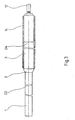
- Fig. 6 shows the finished roller.
- Commercially available precision tubes are used as the support tube 3, which apart from cutting to length make no further work steps necessary.
- the covers 9 and 13 are pressed in.
- the tubular one soft-elastic body 14 is ground to the desired diameter.
- the support tube 3 can be made of virtually any material that has the required strength. By eliminating the vulcanization of a rubber layer, you are not bound to steel pipes.
Landscapes
- Engineering & Computer Science (AREA)
- Mechanical Engineering (AREA)
- Manufacturing & Machinery (AREA)
- Lining Or Joining Of Plastics Or The Like (AREA)
- Rolls And Other Rotary Bodies (AREA)
Abstract
Description
- Die Erfindung betrifft ein Verfahren zum Aufbringen einer weichelastischen Schicht auf Walzen, die in graphischen Maschinen wie Druckmaschinen oder Beschichtungsmaschinen verwendet werden, nach dem Oberbegriff des Anspruchs 1 sowie eine Vorrichtung zur Durchführung des Verfahrens.
- Derartige Walzen werden beispielsweise in Druckmaschinen als Uebertragungs- und Auftragswalzen in Farb- und Feuchtwerken eingesetzt. Sie müssen, da sie als Verbindungswalzen zwischen Walzen mit harter Oberfläche dienen, eine weichelastische Oberfläche aufweisen. Des weiteren muss ihre Oberfläche so beschaffen sein, dass sie die entsprechenden Medien problemlos übertragen können.
- Die Walzen werden normalerweise durch Aufvulkanisation einer weichelastischen Schicht auf einen rohrförmigen Stahlkörper hergestellt. In den meisten Fällen besteht das aufvulkanisierte Material aus einer Gummimischung. Die aufvulkanisierte Gummischicht wird dann auf das erforderliche Mass geschliffen.
- Derartige Walzen erreichen erst nach einer längeren Alterungszeit der Gummischicht eine praktisch konstante Masshaltigkeit. Insbesondere bei auszuwechselnden Walzen, die oftmals neu hergestellt werden müssen, ergibt der sofortige Einsatz infolge der sich veränderten Abmessungen Probleme.
- Derartige Walzen müssen ständig neu einjustiert werden. Das Aufvulkanisieren der Gummischicht ist speziell für auszuwechselnde Walzen sehr aufwendig und teuer, da dies meistens Einzelanfertigungen oder Anfertigungen geringer Stückzahl sind. Auch ist es erforderlich, das Tragrohr wegen der dabei auftretenden Temperaturen aus einem metallischen Werkstoff zu fertigen. Tragrohre aus kohlenstofffaserverstärktem Kunststoff zur Erhöhung der Stabilität und zur Verringerung des Gewichts sind nicht geeignet.
- Der Erfindung liegt die Aufgabe zugrunde, ein Verfahren zu schaffen, mit welchen auf einfache, zeitsparende und billige Art Walzen mit einer weichelastischen Schicht ausgerüstet werden, die sofort einsetzbar sind.
- Erfindungsgemäss erfolgt die Lösung der Aufgabe durch die Merkmale in der Kennzeichnung des Anspruchs 1.
- Mit diesem Verfahren ist es möglich, den schlauchförmigen weichelastischen Körper derart auf das Tragrohr aufzuziehen, dass er vorgespannt ist, wodurch in bestimmten Fällen auf eine Klebung verzichtet werden kann.
- Vorteilhafte Ausgestaltungen der Vorrichtung zur Durchführung des Verfahrens ergeben sich aus den weiteren Ansprüchen.
- Sehr einfach wird die Handhabung, wenn das Stützrohr einseitig mit einem Deckel verschlossen ist, welcher mittig mit einem achsialen Gewindeloch versehen ist. In dieses Gewindeloch ist das Uebergangsstück einschraubbar. Das Tragrohr wird ebenfalls beidseitig mit Deckeln abgeschlossen, die ihrerseits zentral angeordnete, axiale Gewindelöcher aufweisen. So lässt sich das Tragrohr ebenfalls auf das Uebergangsstück aufschrauben.
- Auf den dem Uebergangsstück gegenüberliegenden Deckel lässt sich ein Druckluftanschluss einschrauben. Die Druckluftzuführung erfolgt dann durch das Tragrohr in das Uebergangsstück. Durch Oeffnungen, die im Uebergangsstück vorzugsweise im Bereich der Verbindungsstelle mit dem Tragrohr angeordnet sind, strömt die Druckluft aus und bildet unter dem aufzuschiebenden schlauchförmigen weichelastischen Körper ein Luftkissen.
- Die Erfindung wird nachfolgend anhand eines Ausführungsbeipiels näher erläutert.
- Es zeigen:
- Fig. 1 eine Ansicht der Anordnung zum Aufziehen des schlauchförmigen weichelastischen Körpers, welcher sich noch auf dem Stützrohr befindet
- Fig. 2 eine Ansicht der Anordnung, in welcher der schlauchförmigen weichelastische Körper aufgezogen wird
- Fig. 3 eine Ansicht der Anordnung mit fertig aufgezogenem schlauchförmigen weichelastischen Körper
- Fig. 4 eine Ansicht des Uebergangsstückes
- Fig. 5 eine Draufsicht auf das Uebergangsstück
- Fig. 6 eine Ansicht der fertigen Walze
- Wie aus Fig. 1 ersichtlich ist, werden ein Stützrohr 1, ein Uebergangsstück 2 und ein Tragrohr 3 axial miteinander verschraubt. Hierbei ist das Uebergangsstück 2 beidseitig mit je einem Gewindezapfen 4, 5 ausgerüstet.
- Gewindezapfen 4 passt dabei in ein Gewindeloch 6, welches in einem Deckel 7 eingelassen ist, der das Stützrohr 1 abschliesst, während der Gewindezapfen 5 in ein Gewindeloch 8 eingeschraubt ist, das im Deckel 9 eingelassen ist, welcher das Tragrohr 3 abschliesst.
- Das Uebergangsstück 2 weist eine konische Oberfläche 10 auf, die die Durchmesservergrösserung von Stützrohr 1 auf Tragrohr 3 überbrückt. Im Bereich der Verbindungsstelle 11 zwischen Uebergangsstück 2 und Tragrohr 3 strömt Druckluft aus, die über ein Druckluftanschlussstück 12, das in den Dekkel 13 eingeschraubt ist, welcher das Tragrohr 3 auf der anderen Seite abschliesst, und das Tragrohr 3 zugeführt wird. Der schlauchförmige weichelastische Körper 14 ist auf das Stützrohr 1 aufgeschoben. Der Aussendurchmesser des Stützrohres 1 ist kleiner als der kleinste tolerierbare Innendurchmesser des schlauchförmigen weichelastischen Körpers 14.
- Der schlauchförmige weichelastische Körper 14 wird nun über die konische Oberfläche 10 des Uebergangsstückes 2 in Richtung Tragrohr 3 geschoben, wie es in Fig. 2 dargestellt ist. Sobald der Anfang des schlauchförmigen weichelastischen Körpers 14 über die Verbindungsstelle 11 geschoben ist, bildet sich durch die ausströmende Druckluft zwischen dem schlauchförmigen weichelastischen Körper 14 und dem Tragrohr 3 ein Luftkissen 15. Dieses Luftkissen 15 ermöglicht ein problemloses und vollständiges Aufziehen des schlauchförmigen weichelastischen Körpers 14 auf das Tragrohr 3, wie es Fig. 3 aufzeigt. Der Aussendurchmesser des Tragrohres 3 ist hierbei grösser als der grösste tolerierbare Innendurchmesser des schlauchförmigen weichelastischen Körpers 14, sodass der auf das Tragrohr 3 aufgezogene schlauchförmige weichelastische Körper 14 immer unter einer gewissen Vorspannung steht.
- Normalerweise wird das Tragrohr 3 vor dem Aufziehen des schlauchförmigen weichelastischen Körpers 14 mit einem Klebemittel beschichtet. Auch hierbei bietet das Aufziehen des schlauchförmigen weichelastischen Körpers 14 wegen des sich aufbauenden Luftkissens 15 keine Probleme. Und da nach Ausschalten der Druckluftquelle sich der schlauchförmige weichelastische Körper 14 durch seine Vorspannung zusammenzieht, ist zum Aushärten des Klebemittels kein zusätzliches Anpressen erforderlich, die Haftung wird optimal.
- Fig. 4 und Fig. 5 zeigen das Uebergangsstück 2. Beidseitig der konischen Oberfläche 10 sind die Gewindezapfen 4 und 5 angeordnet. Der Gewindezapfen 5, der in den Deckel 9 des Tragrohres 3 eingeschraubt wird, weist im Zentrum eine axiale Bohrung 16 auf. In diese Bohrung 16 münden praktisch radial angebrachte Löcher 17, die die Bohrung 16 mit einem Ringkanal 18 verbinden. Dieser Ringkanal 18 ist in die stirnseitige Fläche 19 der konischen Oberfläche 10 mit dem grossen Durchmesser ums Zentrum eingelassen. Radial angeordnete Nuten 20 dienen als Durchlass für die Druckluft, die durch das Tragrohr 3 eingebracht wird, zum Ausströmen im Bereich der Verbindungsstelle 11 zwischen Uebergangsstück 2 und Tragrohr 3.
- Die konische Oberfläche 10 weist an ihrer dicksten Stelle, die mit dem Tragrohr 3 in Verbindung kommt, einen grösseren Durchmesser auf, als das Tragrohr 3 selbst. Dieser mit einer Abrundung 21 versehene, über das Tragrohr 3 vorstehende Bereich dient quasi als Dichtung für die Druckluft, damit sie nicht in Richtung des Stützrohres 1 unter dem aufzuziehenden schlauchförmigen weichelastischen Körper 14 wegfliessen kann.
- Fig. 6 zeigt die fertige Walze. Als Tragrohr 3 werden handelsübliche Präzisionsrohre verwendet, die ausser Ablängen keine weiteren Arbeitsschritte erforderlich machen. Die Deckel 9 und 13 werden eingepresst. Der schlauchförmige weichelastische Körper 14 wird auf den gewünschten Durchmesser abgeschliffen.
- Das Tragrohr 3 kann aus einem praktisch beliebigen Material bestehen, das die erforderliche Festigkeit aufweist. Durch das Wegfallen der Aufvulkanisierung einer Gummischicht ist man nicht an Rohre aus Stahl gebunden.
Claims (6)
- dass das weichelastische Material, mit welchem die Walze beschichtet wird, als schlauchförmiger Körper (14) vorliegt, welcher auf eine Länge gebracht wird, die der Walzenbreite entspricht,
- dass der schlauchförmige, weichelastische Körper (14) auf ein Stützrohr (1) aufgeschoben wird,
- dass das Stützrohr (1) mit dem aufgeschobenen schlauchförmigen, weichelastischen Körper (14) mit einem Uebergangsstück (2) mit dem Tragrohr (3) axial verbunden wird,
- dass Druckluft zugeführt wird, die im Bereich des Uebergangstückes (2) ausströmt,
- dass der schlauchförmige weichelastische Körper (14) vom Stützrohr (1) über das Uebergangsstück (2) auf dem sich aufbauenden Luftkissen (15) vollständig auf das Tragrohr (3) aufgeschoben wird.
Applications Claiming Priority (2)
| Application Number | Priority Date | Filing Date | Title |
|---|---|---|---|
| DE3921037 | 1989-06-27 | ||
| DE3921037A DE3921037A1 (de) | 1989-06-27 | 1989-06-27 | Verfahren und vorrichtung zum aufbringen einer weichelastischen schicht auf walzen fuer graphische maschinen |
Publications (3)
| Publication Number | Publication Date |
|---|---|
| EP0406172A2 true EP0406172A2 (de) | 1991-01-02 |
| EP0406172A3 EP0406172A3 (en) | 1992-02-26 |
| EP0406172B1 EP0406172B1 (de) | 1995-03-08 |
Family
ID=6383685
Family Applications (1)
| Application Number | Title | Priority Date | Filing Date |
|---|---|---|---|
| EP90810466A Expired - Lifetime EP0406172B1 (de) | 1989-06-27 | 1990-06-21 | Vorrichtung zum Aufbringen einer weichelastischen Schicht auf Walzen für graphische Maschinen |
Country Status (3)
| Country | Link |
|---|---|
| US (1) | US5143573A (de) |
| EP (1) | EP0406172B1 (de) |
| DE (1) | DE3921037A1 (de) |
Cited By (6)
| Publication number | Priority date | Publication date | Assignee | Title |
|---|---|---|---|---|
| EP0590924A1 (de) * | 1992-09-29 | 1994-04-06 | Xerox Corporation | Flexible Rohre, abgestützt auf starren Trommeln, und ihr Herstellungsverfahren |
| US5413810A (en) * | 1994-01-03 | 1995-05-09 | Xerox Corporation | Fabricating electrostatographic imaging members |
| US5443785A (en) * | 1994-01-03 | 1995-08-22 | Xerox Corporation | Method of treating seamless belt substrates and carriers therefor |
| WO1996011100A1 (de) * | 1994-10-07 | 1996-04-18 | Urenco Deutschland Gmbh | Verfahren zum herstellen von faserverbundrohren mit metallischer oberfläche |
| EP1195654A3 (de) * | 2000-10-04 | 2009-07-01 | Eastman Kodak Company | Übertragungselement mit einer austauschbaren Hülse und Verfahren zu Verwendung desselben |
| ITMO20100093A1 (it) * | 2010-03-31 | 2011-10-01 | Paolo Mesini | Procedimento per la realizzazione di un dispositivo per la decorazione rotativa di manufatti ceramici e dispositivo cosi' realizzato. |
Families Citing this family (16)
| Publication number | Priority date | Publication date | Assignee | Title |
|---|---|---|---|---|
| FR2668098A1 (fr) * | 1990-10-17 | 1992-04-24 | Aerospatiale | Procede pour fretter et maintenir sous pression un noyau par une enveloppe en materiau composite et appareillage pour la mise en óoeuvre d'un tel procede. |
| US5473354A (en) * | 1994-05-26 | 1995-12-05 | Hewlett-Packard Company | Ink-delivery apparatus |
| US5709765A (en) * | 1994-10-31 | 1998-01-20 | Xerox Corporation | Flexible belt system |
| US5952017A (en) * | 1994-12-16 | 1999-09-14 | Taisei Kako Co., Ltd. | Pressure roll, and molding apparatus using the pressure roll |
| US5885512A (en) * | 1997-10-01 | 1999-03-23 | Xerox Corporation | Method of treating preformed flexible imaging belts to form ripple-free and dimensionally precise belts |
| AUPP058197A0 (en) * | 1997-11-27 | 1997-12-18 | A.I. Scientific Pty Ltd | Pathology sample tube distributor |
| US6076217A (en) * | 1998-04-06 | 2000-06-20 | Micron Technology, Inc. | Brush alignment platform |
| CN1169662C (zh) * | 2000-06-19 | 2004-10-06 | 四维企业股份有限公司 | 用于改变胶带纸芯的商标纸的方法 |
| US6463250B1 (en) | 2000-10-04 | 2002-10-08 | Nexpress Solutions Llc | Externally heated deformable fuser roller |
| US6456816B1 (en) | 2000-10-04 | 2002-09-24 | Nexpress Solutions Llc | Method and apparatus for an intermediate image transfer member |
| US6393247B1 (en) | 2000-10-04 | 2002-05-21 | Nexpress Solutions Llc | Toner fusing station having an internally heated fuser roller |
| US6490430B1 (en) | 2000-10-04 | 2002-12-03 | Nexpress Solutions Llc | Externally heated roller for a toner fusing station |
| KR101437179B1 (ko) * | 2008-09-03 | 2014-09-03 | 코오롱인더스트리 주식회사 | 무솔기 벨트 |
| US20100212810A1 (en) * | 2009-02-24 | 2010-08-26 | James Michael S | Sleeve device, tire building apparatus, and method |
| US20110135348A1 (en) * | 2009-12-03 | 2011-06-09 | Xerox Corporation | Simple itb steering rib applicator |
| DE102017000008A1 (de) | 2017-01-02 | 2018-07-05 | Fresenius Medical Care Deutschland Gmbh | Verfahren und Vorrichtung zum Aufstecken eines Schlauches auf eine formstabile Tülle |
Family Cites Families (13)
| Publication number | Priority date | Publication date | Assignee | Title |
|---|---|---|---|---|
| US1801396A (en) * | 1926-09-24 | 1931-04-21 | Underwood Elliott Fisher Co | Typewriting machine |
| US2645004A (en) * | 1948-01-27 | 1953-07-14 | Goodrich Co B F | Method of and apparatus for assembling flexible tubing upon mandrels |
| US2721601A (en) * | 1950-11-20 | 1955-10-25 | Perma Flex Ind Ltd | Method of forming printing roller cores |
| DE1189688B (de) * | 1959-04-18 | 1965-03-25 | Busch Jaeger Duerener Metall | Verfahren zum Aufschieben von Schlaeuchen aus halbelastischem Material auf Metallrohrteile von Liegestuehlen |
| US3146709A (en) * | 1962-04-09 | 1964-09-01 | West Essex Printing Plate Inc | Method and apparatus for mounting printing sleeves |
| DE1753626A1 (de) * | 1968-01-24 | 1971-07-29 | Hoechst Ag | Verfahren und Vorrichtung zur Herstellung von Halbschlaeuchen aus Kunststoff-Flachfolien |
| DE1932320C3 (de) * | 1969-06-26 | 1975-01-23 | Stahlgruber Otto Gruber & Co, 8000 Muenchen | Verfahren zum Herstellen eines schlauchförmigen GummHiberzuges für eine FörderbandroHe |
| US3776682A (en) * | 1971-04-26 | 1973-12-04 | Rieber & Son Plastic Ind As | Apparatus for producing radially-expanded socket ends on thermoplastic pipe lengths |
| US3846901A (en) * | 1972-01-10 | 1974-11-12 | J Lovett | Method of mounting a resilient sleeve on a conveyor roller |
| US3900941A (en) * | 1974-02-08 | 1975-08-26 | Dayco Corp | Apparatus for and method of installing an expandible sleeve |
| DE2515682A1 (de) * | 1975-04-10 | 1976-10-21 | Continental Gummi Werke Ag | Verfahren zum aufbringen elastischer bezuege auf walzen |
| NO152118C (no) * | 1983-05-09 | 1985-08-07 | Svein Groedum | Fremgangsmaate for fremstilling av plastbelagt fargevalse til trykkpresse |
| IT1199660B (it) * | 1984-02-24 | 1988-12-30 | Pirelli General Plc | Applicazione di un manicotto elastico su un corpo allungato |
-
1989
- 1989-06-27 DE DE3921037A patent/DE3921037A1/de active Granted
-
1990
- 1990-06-21 EP EP90810466A patent/EP0406172B1/de not_active Expired - Lifetime
- 1990-06-26 US US07/544,207 patent/US5143573A/en not_active Expired - Fee Related
Cited By (7)
| Publication number | Priority date | Publication date | Assignee | Title |
|---|---|---|---|---|
| EP0590924A1 (de) * | 1992-09-29 | 1994-04-06 | Xerox Corporation | Flexible Rohre, abgestützt auf starren Trommeln, und ihr Herstellungsverfahren |
| US5518854A (en) * | 1992-09-29 | 1996-05-21 | Xerox Corporation | Flexible tubes supported on rigid drum |
| US5413810A (en) * | 1994-01-03 | 1995-05-09 | Xerox Corporation | Fabricating electrostatographic imaging members |
| US5443785A (en) * | 1994-01-03 | 1995-08-22 | Xerox Corporation | Method of treating seamless belt substrates and carriers therefor |
| WO1996011100A1 (de) * | 1994-10-07 | 1996-04-18 | Urenco Deutschland Gmbh | Verfahren zum herstellen von faserverbundrohren mit metallischer oberfläche |
| EP1195654A3 (de) * | 2000-10-04 | 2009-07-01 | Eastman Kodak Company | Übertragungselement mit einer austauschbaren Hülse und Verfahren zu Verwendung desselben |
| ITMO20100093A1 (it) * | 2010-03-31 | 2011-10-01 | Paolo Mesini | Procedimento per la realizzazione di un dispositivo per la decorazione rotativa di manufatti ceramici e dispositivo cosi' realizzato. |
Also Published As
| Publication number | Publication date |
|---|---|
| EP0406172A3 (en) | 1992-02-26 |
| EP0406172B1 (de) | 1995-03-08 |
| DE3921037C2 (de) | 1991-10-17 |
| US5143573A (en) | 1992-09-01 |
| DE3921037A1 (de) | 1991-01-10 |
Similar Documents
| Publication | Publication Date | Title |
|---|---|---|
| EP0406172A2 (de) | Vorrichtung zum Aufbringen einer weichelastischen Schicht auf Walzen für graphische Maschinen | |
| DE4217793C1 (de) | Offset-Gummituch und Verfahren zu dessen Herstellung | |
| DE29518150U1 (de) | Nahtlose Druckhülse, insbesondere für einen Flexodruckzylinder | |
| EP0819550A2 (de) | Gummizylinderhülse, insbesondere für Offset-Rollenrotationsdruckmaschinen | |
| DE3105171A1 (de) | Schleppwalze zur druckbehandlung von warenbahnen | |
| DE1575639B2 (de) | Walze und Verfahren zum Herstellen derselben | |
| DE2807343C2 (de) | Vorrichtung zur Befestigung eines Fahrzeugrades auf der Welle einer Auswuchtmaschine | |
| DE202014003409U1 (de) | Führungswalze eines Einzugswalzenpaares einer Granuliervorrichtung | |
| DE10025374A1 (de) | Gummizylinderhülse, insbesondere für Offset-Rollenrotationsdruckmaschinen | |
| DE2504882A1 (de) | Verfahren und vorrichtung zum aufbringen einer federnd dehnbaren spannhuelse | |
| DE19520065A1 (de) | Verfahren zur Herstellung einer Klebverbindung und damit hergestellte Anordnung | |
| DE4431648C1 (de) | Andrückwalze für das Andrücken einer laufenden Warenbahn | |
| EP1144200B1 (de) | Hülse aus thermisch verformbarem material sowie verfahren zu deren herstellung | |
| EP0406171B1 (de) | Verfahren und Vorrichtung zur Herstellung von Klebewalzen für Rollenwechsler von bahnverarbeitenden Maschinen insbesondere Rollenrotations-Druckmaschinen | |
| DE69717592T2 (de) | Verfahren zur Montage einer Hülse in den Sitz eines Gehäuses und Vorrichtung undWerkzeug für diese Montage | |
| DE2710830A1 (de) | Endarmatur fuer mehrkanalschlaeuche | |
| DE3007943C2 (de) | Durchbiegungseinstellwalze | |
| DE19719969C2 (de) | Verfahren und Vorrichtung zum Sanieren von Hausanschlußbereichen an Abwasserrohren bzw. -kanälen | |
| DE10303386B4 (de) | Elastomer-beschichtete Walze | |
| DE4231961A1 (de) | Vorrichtung zum Einbringen von Innenmänteln in Kanäle, insbesondere Abwasserkanäle, Abwasserrohre o. dgl. | |
| EP0743181B1 (de) | Vorrichtung zum Verteilen von fliessfähigem Medium | |
| DE2910391C2 (de) | Anordnung zur Befestigung von Stützringen auf den Zapfen der Zylinder von Druckmaschinen | |
| DE19638321A1 (de) | Gleitringdichtung mit Stützring | |
| DE3338965A1 (de) | Vorrichtung zum dehnen und/oder streichen einer bewegten bahn | |
| DE2058955B2 (de) | Verfahren und vorrichtung zum herstellen einer gummiwalze |
Legal Events
| Date | Code | Title | Description |
|---|---|---|---|
| PUAI | Public reference made under article 153(3) epc to a published international application that has entered the european phase |
Free format text: ORIGINAL CODE: 0009012 |
|
| AK | Designated contracting states |
Kind code of ref document: A2 Designated state(s): CH FR GB IT LI SE |
|
| PUAL | Search report despatched |
Free format text: ORIGINAL CODE: 0009013 |
|
| AK | Designated contracting states |
Kind code of ref document: A3 Designated state(s): CH FR GB IT LI SE |
|
| 17P | Request for examination filed |
Effective date: 19920710 |
|
| 17Q | First examination report despatched |
Effective date: 19930909 |
|
| GRAA | (expected) grant |
Free format text: ORIGINAL CODE: 0009210 |
|
| AK | Designated contracting states |
Kind code of ref document: B1 Designated state(s): CH FR GB IT LI SE |
|
| GBT | Gb: translation of ep patent filed (gb section 77(6)(a)/1977) |
Effective date: 19950329 |
|
| ET | Fr: translation filed | ||
| ITF | It: translation for a ep patent filed | ||
| PLBE | No opposition filed within time limit |
Free format text: ORIGINAL CODE: 0009261 |
|
| STAA | Information on the status of an ep patent application or granted ep patent |
Free format text: STATUS: NO OPPOSITION FILED WITHIN TIME LIMIT |
|
| 26N | No opposition filed | ||
| PGFP | Annual fee paid to national office [announced via postgrant information from national office to epo] |
Ref country code: GB Payment date: 20010618 Year of fee payment: 12 |
|
| PGFP | Annual fee paid to national office [announced via postgrant information from national office to epo] |
Ref country code: FR Payment date: 20010622 Year of fee payment: 12 |
|
| PGFP | Annual fee paid to national office [announced via postgrant information from national office to epo] |
Ref country code: SE Payment date: 20010626 Year of fee payment: 12 |
|
| PGFP | Annual fee paid to national office [announced via postgrant information from national office to epo] |
Ref country code: CH Payment date: 20010925 Year of fee payment: 12 |
|
| REG | Reference to a national code |
Ref country code: GB Ref legal event code: IF02 |
|
| PG25 | Lapsed in a contracting state [announced via postgrant information from national office to epo] |
Ref country code: GB Free format text: LAPSE BECAUSE OF NON-PAYMENT OF DUE FEES Effective date: 20020621 |
|
| PG25 | Lapsed in a contracting state [announced via postgrant information from national office to epo] |
Ref country code: SE Free format text: LAPSE BECAUSE OF NON-PAYMENT OF DUE FEES Effective date: 20020622 |
|
| PG25 | Lapsed in a contracting state [announced via postgrant information from national office to epo] |
Ref country code: LI Free format text: LAPSE BECAUSE OF NON-PAYMENT OF DUE FEES Effective date: 20020630 Ref country code: CH Free format text: LAPSE BECAUSE OF NON-PAYMENT OF DUE FEES Effective date: 20020630 |
|
| EUG | Se: european patent has lapsed | ||
| GBPC | Gb: european patent ceased through non-payment of renewal fee |
Effective date: 20020621 |
|
| REG | Reference to a national code |
Ref country code: CH Ref legal event code: PL |
|
| PG25 | Lapsed in a contracting state [announced via postgrant information from national office to epo] |
Ref country code: FR Free format text: LAPSE BECAUSE OF NON-PAYMENT OF DUE FEES Effective date: 20030228 |
|
| REG | Reference to a national code |
Ref country code: FR Ref legal event code: ST |
|
| PG25 | Lapsed in a contracting state [announced via postgrant information from national office to epo] |
Ref country code: IT Free format text: LAPSE BECAUSE OF NON-PAYMENT OF DUE FEES;WARNING: LAPSES OF ITALIAN PATENTS WITH EFFECTIVE DATE BEFORE 2007 MAY HAVE OCCURRED AT ANY TIME BEFORE 2007. THE CORRECT EFFECTIVE DATE MAY BE DIFFERENT FROM THE ONE RECORDED. Effective date: 20050621 |